
Related Manuals for Sunamp UniQ eHW Series


Summary of Contents for Sunamp UniQ eHW Series
- Page 1 Keep these instructions in a safe place for future reference Keep these instructions in a safe place for future reference. UniQ eHW Heat Battery Installation and User Manual UniQ eHW Heat Batteries Installation and User Manual...
- Page 2 ONLY competent persons who are suitably qualified to carry out plumbing and electrical work and have successfully completed product training by Sunamp Ltd or an authorised training partner may undertake installations, repairs or relocations. The system must be earthed correctly and have its own independent electrical supply with correct voltage and circuit breakers.
-
Page 3: Table Of Contents
To instruct competent persons on how to safely install UniQ eHW Heat Batteries. Competent persons are those suitably qualified to carry out plumbing and electrical work and have successfully completed product training by Sunamp Ltd or an authorised training partner. Contents Safety Instructions ...................... -
Page 4: Safety Instructions
Safety Instructions Sunamp Ltd is not responsible for the failure of components not specified in this manual and/or supplied by other manufacturers. Intended Use The intended use of the UniQ eHW range of products is for the provision of hot water for domestic purposes by means of electric charging of the Heat Battery. -
Page 5: Electrical Safety
• All hot works (such as soldering, welding or brazing) must be performed on tubes detached from the heat battery (minimum 1 metre away). • This product is NOT suitable for tank fed hot water system. • Do not immerse this product in water or any other liquid. Electrical Safety •... -
Page 6: User Competence, Qualification, And Approval
User Competence, Qualification, and Approval • ONLY competent persons who are suitably qualified to carry out plumbing and electrical work and have successfully completed product training by Sunamp Ltd or an authorised training partner may undertake installations, repairs or relocations. •... -
Page 7: Post-Installation Safety
Post-Installation Safety • All goods are sold subject to Sunamp Ltd’s ‘Conditions of Sale’, as listed on the company website. • As Sunamp Ltd continuously improves products, they may be modified without notice. In such circumstances this manual and other relevant documentation should be disregarded. -
Page 8: Uniq Ehw Heat Battery Overview
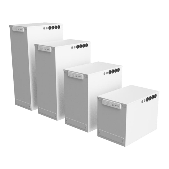
UniQ eHW Heat Battery Overview Introduction Thank you for choosing a Sunamp Ltd UniQ Heat Battery, our innovative, super-compact heat storage system based on phase-change materials (PCM). We are sure you will be delighted with the performance, compactness, ease of installation and quality of our product. -
Page 9: Product Overview
Product Overview Figure 1: Heat Battery (external) Item Description Heat Battery – main body Heat Battery – lid Data badge / serial number Controller interface Terminal cover plate Tube entries (3 sides) Cable entries (3 sides) Energy label – to be applied by installer (if applicable) Table 1: Product overview (external) - Page 10 Figure 2: Heat Battery (internal) Item Description Insulation layers – to be cut to suit copper tube and cable entries Temperature sensor Electrical control box – PCB, relays, terminal block Non-self-resetting overheat thermostat (OHT) Table 2: Product overview (internal)
-
Page 11: Product Identification
Product Identification Figure 3: Heat Battery views showing the three tube exits Item Description Item Description Earth Clamp (supplied) - to be Cable Entry via Gland - supplied but clamped to Ø22mm copper tube not fitted Cold Water Inlet – ‘A’ – Ø22mm Ø22mm Copper Tube... -
Page 12: Accessories And Parts
C5379 22mm Tectite Pro Tee TX24 65676 C5412 Conex BM8090 0220000 22mm >B<Push elbow Table 5: Accessories Note: 2 x C5377/C5412 are supplied with the product as standard. Visit our website (www.sunamp.com) for all the latest accessories and spare parts. -
Page 13: Technical Specifications
Table 6: Model specific dimensions. Net Weight refers to an empty Heat Battery (i.e. no water in the tubes); Gross Weight refers to tubes being filled with water. Figure 5: Additional Sunamp Ltd UniQ eHW Heat Battery dimensions Item Description... - Page 14 2.5.2 Detailed Specifications Specification Size 3 Size 6 Size 9 See Note Heat storage capacity (kWh) 10.5 Water Content (L) Equivalent Hot Water Cylinder Size (L) , Volume of Hot water available at 40°C (L) Standby heat loss rate (kWh / 24h | (W)) 0.48 | (20) 0.67 | (28.1) 0.77 | (32.1)
- Page 15 Recommended setting range for hot water thermostatic mixing valve. When installed as an electric water heater. Tested to standard: BS EN 50440:2015 For more detailed specifications, also see the UniQ Heat Batteries General Product Application and Design Manual, available from the downloads section of our website (www.sunamp.com).
-
Page 16: Pressure Loss Characteristics
Pressure Loss Characteristics Pressure loss characteristics can be calculated using the graph below (Figure 6.1). The points that the pressure loss for the Heat Battery are displayed in (Figure 6.2) 0.35 Size 3 0.25 Size 6 0.15 Size 9 0.05 Flow Rate (L/min) Figure 6.1: UniQ eHW Heat Battery pressure loss characteristics graph Figure 6.2: Pressure loss at inlet &... -
Page 17: Installation
Installation Always read the safety instructions in Section 1 of the manual before installing UniQ eHW Heat Batteries. Installation Process Preparation: • Assess the location of installation considering spatial requirements, clearances, cable runs and tube runs. • Unpack and discard or recycle packaging according to local disposal or recycling rules. - Page 18 Deburr the tube end, both internally and externally to create a 1mm chamfer on the outside of the tube. Check the tube ends are free from damage and clean, wiping away any swarf to avoid damaging the ‘O’ ring on tube insertion. Tube end must also be free from stickers, tape and adhesive residues.
- Page 19 Final Fit After Commissioning: Commissioning instructions are provided in Section 4 of this manual. Follow the instructions below after commissioning. • Cut the 32mm thick insulation layer to suit the tube and cable entries. This layer has several perforations for guidance. This can be done with a sharp knife or scissors.
-
Page 20: Water Supply Requirements
For information regarding expansion vessel sizing and pressure relief valves, refer to the UniQ Heat Batteries Reference Manual, available from downloads section of our website (www.sunamp.com). Important: Although the Heat Batteries are designed for 1.0MPa (10 bar) maximum working pressure, it is recommended that if the incoming mains pressure is greater than 0.5MPa (5 bar), a WRAS approved pressure... -
Page 21: Location And Space Requirements
• Minimum - Maximum dynamic mains water supply pressure: 0.15MPa (1.5 bar) - 1.0MPa (10 bar). • Minimum mains cold and hot water tube sizes: Ø22mm copper or equivalent. • Expansion vessel charge pressure = incoming mains pressure (MPa). • A potable water expansion relief valve is only required when the water cannot expand back into the mains (e.g. - Page 22 Figure 9: Spacing (in mm) surrounding the Heat Battery Item Space Reason 150mm To access terminal cover and to ensure visibility of the data badge and LEDs 450mm To remove lid and access internals 150mm To allow for tube and cables entry (side dependent) 10mm If no access required (side dependent) <...
-
Page 23: Hydraulic Requirements
Hydraulic Requirements Sunamp Ltd Heat Batteries are NOT suitable for tank-fed hot water systems. • All connection tube work inside the Heat Battery casing must be Ø22mm copper tube. This is to allow the earth connection between the case, inlet, and outlet tube fittings. -
Page 24: Electrical And Wiring Requirements
Electrical and Wiring Requirements All range models within this manual are fitted with an internal controller situated at the top of the Heat Battery. Two wiring options are available: 1. No time-switch: 24-hour electricity grid supply only. 2. Time-switch: Standard electricity grid supply only. Zero Volt Time switch with options for tariffs such as E7 and E10. - Page 25 • The mains power cable to the Sunamp Controller should be a minimum of 2.5mm², 3 core HO5 VV-F sheathed cable, to BS 6500. This cable must be prepared according to Figure 10 (below), where the Green/ Yellow (Protective Earth) wire is 15mm longer than the Brown (Live) and Blue (Neutral) wires.
- Page 26 3.6.2 Controller Wiring Diagram Figure 11: Internal controller wiring diagram (wire sizes=0.75mm , unless stated otherwise)
-
Page 27: Wiring Option 1 - 24H Grid Supply Without Time-Switch
Wiring Option 1 – 24h Grid Supply Without Time-Switch Important: Please follow (Table 13) for information regarding the Links. Link specification Removed or Fixed Link 1 Fixed Link 2 Fixed Charge Link Fixed Table 13: Link settings wiring option 1 – 24h Grid supply without time-switch •... - Page 28 3.7.1 Controller Wiring Schematic and Diagram Figure 12.1: Example wiring option 1 schematic (see Figure 3 for piping and electrical options available) Item Description Mains cold water supply Local 2-pole isolator, 13A Check valve 230VAC, 16A power supply Cold Water pressure Water Thermostatic...
- Page 29 Link 1 Link 2 Charge Link Live Neutral Earth 2.5 mm , 3 Core HT Flex Controller Case Strain Relief White Case Local 2 Pole 13A Isolator ~230V, 16A supply Figure 12.2: Wiring option 1 diagram – 24h Grid supply without time-switch...
-
Page 30: Wiring Option 2 - On-/Off-Peak Tariff With External Time-Switch
Wiring Option 2 – On-/Off-Peak Tariff with External Time- Switch Important: Please follow (Table 15) for information regarding the Links. Link specification Removed or Fixed Link 1 Fixed Link 2 Fixed Charge Link Removed Table 15: Link settings for wiring option 2 – on/off-peak tariff with external time-switch •... - Page 31 3.8.2 Controller Wiring Schematic and Diagram Figure 13.1: Example wiring option 2 schematic (see Figure 3 for tubing and electrical options available) Item Description Mains cold water supply Local 2-pole isolator, 3A Check valve 230VAC, spurred fused power supply Cold Water pressure Water...
- Page 32 Link 1 Link 2 Live Neutral Earth 2.5 mm , 3 Core HT Flex Controller Case Strain Relief White Case Time switch volt free Local 2 Pole 13A Isolator Signal switching 3A Fused spur CC ~230V, 16A supply supply Figure 13.2: Wiring option 2 – on-/off-peak tariff with external time-switch...
-
Page 33: Commissioning
Commissioning Before commissioning the product, first ensure that you have properly reviewed the previous sections, particularly in regard to Heat Battery specifications as well as location, electrical supply and water supply requirements. Preparation • Ensure all packaging material has been removed. •... - Page 34 (which may otherwise indicate an error, see Table 17). 13. Leave all product information and literature with the customer/end user. 14. Fill in and return the Sunamp Ltd commissioning certificate, provided with the product. These documents MUST be compiled and returned...
-
Page 35: Operation
Operation Always read the safety instructions in Section 1 of the manual before operating the UniQ eHW Heat Batteries. Switch On/Off Power is supplied to the Heat Battery via the 2-pole Isolator Switch. The Heat Battery will remain in operation whilst it is connected to the mains. The Heat Battery will switch off if you disconnect it from the mains. -
Page 36: Troubleshooting
3. Reset the non-self-resetting thermal cut-out 4. Reassemble the unit, and 5. Reconnect the supply If the problem persists, please contact Sunamp Ltd. LED D4 (power Temperature sensor Check that the sensor cable is symbol) is string is faulty... - Page 37 5.3.2 After Installation or During Use Warning: This product does not contain any user-serviceable or user- settable components. All fault-finding and fault-remediation works therefore need to be carried out by a competent person Fault Possible Cause(s) Possible Solution No hot water Power supply has been Check power supply.
-
Page 38: Maintenance
Maintenance Where undertaking maintenance, repairs or removals, and where necessary, ensure that the system is first disconnected from the electrical and/or water supply. • The product does NOT require any regular maintenance. • In areas, where the mains water hardness can exceed 150 ppm total hardness and a scale-reducing device has been fitted, the service and maintenance requirements... -
Page 39: Warranty
Warranty Information regarding product warranty can be found on the Sunamp Ltd website: www.sunamp.com/warranty. Recycling and Disposal This symbol on the product and accompanying documents means the product should not be mixed with general household waste at the end of its life. - Page 40 Manual Part Number: D0001 Version Number: 1.1 Publication Date: 14/07/2020 Sunamp Ltd. 1 Satellite Park Macmerry East Lothian Scotland, EH33 1RY General Enquiries +44 (0)1875 610001 info@sunamp.com www.sunamp.com...
Need help?
Do you have a question about the UniQ eHW Series and is the answer not in the manual?
Questions and answers