Table of Contents
Advertisement
Quick Links
OPERATOR'S MANUAL
Including Assembly and Operating Instructions and Parts List
ROWSE HYDRAULIC RAKES COMPANY, INC.
84504 State Hwy 11
Burwell, Nebraska 68823
Phone: 308-348-2276
Fax: 308-348-2059
Toll-Free: 800-652-1912
Toll-Free 800-445-9202
E-mail: rowserakes@rowserakes.com
AND
PARTS LIST
Website: www.rowserakes.com
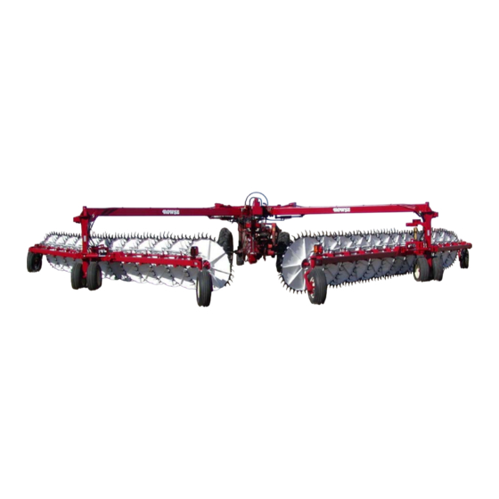
V-Rake
304 Simpson Road
O'Neill, Nebraska 68763
Phone: 402-336-3255
Fax: 402-336-3272
Toll-Free: 877-336-3255
E-mail: rowserakesatoneill@telebeep.com
Advertisement
Table of Contents
Troubleshooting

Summary of Contents for Rowse Ultimate V-Rake
- Page 1 V-Rake OPERATOR’S MANUAL PARTS LIST Including Assembly and Operating Instructions and Parts List ROWSE HYDRAULIC RAKES COMPANY, INC. 84504 State Hwy 11 304 Simpson Road Burwell, Nebraska 68823 O’Neill, Nebraska 68763 Phone: 308-348-2276 Phone: 402-336-3255 Fax: 308-348-2059 Fax: 402-336-3272 Toll-Free: 800-652-1912...
- Page 2 ULTIMATE V-RAKE: RIGHT UPPER ARM Page 55 -- Parts ULTIMATE V-RAKE: MAIN Page 59 -- Parts ULTIMATE V-RAKE: RIGHT MIDDLE LEG Page 51 -- Parts ULTIMATE V-RAKE: RIGHT WING Page 41 -- Parts ULTIMATE V-RAKE: COMPLETE...
- Page 3 ULTIMATE V-RAKE: ADJUSTABLE MAIN Page 63 -- Parts ULTIMATE V-RAKE: LEFT MIDDLE LEG Page 53 -- Parts ULTIMATE V-RAKE: LEFT WING Page 41 -- Parts ULTIMATE V-RAKE: LEFT UPPER ARM Page 57 -- Parts...
- Page 4 Safety Service Troubleshooting Parts List SERIAL NO. ________________________ PURCHASE DATE: _____________________ ROWSE HYDRAULIC RAKES CO., INC 84504 State Hwy 11, Burwell, Nebraska 68823 304 Simpson Road, O’Neill, Nebraska 68763 Phone: 308-348-2276 Fax: 308-348-2059 Phone: 402-336-3255 Fax: 402-336-3272 Toll-Free: 800-652-1912 Toll-Free: 877-336-3255 Toll-Free 800-445-9202 E-mail: rowserakesatoneill@telebeep.com...
-
Page 5: Table Of Contents
Excessive Breakage of Teeth Rake Wings Not Holding Position (Width) SECTION B: ASSEMBLY INSTRUCTIONS Raking Wheels Will Not Go Down Ultimate V-Rake Models Discussed Castor Wheels Shimmy (Wobble) Serial Number Raking Wheels Won’t Go Down on Assembly, Terminology, Terms & Phrases... -
Page 6: Section A: Introduction
General Outline Of This Manual Congratulations on your selection of the Rowse Information in this manual is arranged under eight Ultimate V-Rake to aid you in your haying operation. This main section headings. operator’s manual will assist you in realizing the benefits Following the introduction, the steps for assembly you can gain from using the Rowse Ultimate V-Rake. -
Page 7: Safety & Special Information
The obli gation of Rowse under this warranty is limited to re pairing or at its option, replacing WARNING F.O.B. -
Page 8: Warranty Details
Rowse allows for warranty equipment previously sold. work. Items Not Covered 1. -
Page 9: Bolt Torque Information
Figure A-7: Bolt Grade Designation Bolt Torque Information 1. Tighten bolts to torques shown in the chart unless SAE-2 SAE-5 SAE-8 otherwise specified. 2. Bolts having locknuts with cadmium or wax finish should be tightened to approximatley 50% of amounts shown on charts. Figure A-8: Bolt Torque Information 3. -
Page 10: Serial Number
Wheel V-Rakes Figure B-1 lists the Models covered in For future reference, record below the model this manual. number and serial number of your Rowse V-Rake. This information is stamped into the frame on the Figure B-1: Model Numbers and top of the left front wing of your V-Rake. -
Page 11: Assembly, Terminology, Terms & Phrases
SECTION B: ASSEMBLY TERMINOLOGY, TERMS AND PHRASES All Rowse Ultimate V-Rakes with which this C. “Inside”, “Outside” or “Outward” — The “Inside” is the section deals with are completely set up and field side closest to the center of the rake. “Outside” is the ready. -
Page 12: Section C: Operating Instructions
CAUTION machine. b) “Front” or “Rear” of the Rake — the “front” is the 1. When hitching the Ultimate V-Rake to the tractor, part closest to the tractor. do not allow anyone to get between the tractor c) “Inside” or “Outside” — The “inside” is the side and the Rake. -
Page 13: Function And Use Of The Sight Gauges
As with any piece of equipment, certain proce dures and guidelines must be followed to assure safety, ease Rowse has equipped your V-Rake with an electric of operation, and operation without damage to the unit over hydraulic control valve which enables you to... -
Page 14: Prior To Positioning Rake
PRIOR TO POSITIONING V-RAKE VERY IMPORTANT 1. Before attempting to position the Ultimate into field position, operator MUST detach Stabilizer Bars from the front of the rake wings. These bars secure the wings to the center frame dur ing transportation of rake. Failure to detach the Stabilizer Bars will result in from moderate to very serious and costly damage. - Page 15 The card is to guide and remind operator of basic positioning procedures. Attach the card to the control box. POSITIONING THE ULTIMATE V-RAKE INTO FIELD POSITION 1. Select the red toggle switch (#1). This controls the arm movement. Switch to “on” position (red light will come on).
-
Page 17: Positioning The Ultimate Rake
POSITIONING THE ULTIMATE RAKE USING THE “TOE IN” FUNCTION If you do not have sufficient area to position rake without putting extreme pressure on the rake legs, the following is the procedure to position the rake using the “toe in” function. IMPORTANT: Detach the front stabilizer bars from the front wings. -
Page 18: Back To Transport Position
POSITIONING THE ULTIMATE V-RAKE BACK TO TRANSPORT POSITION To position the rake back to transport position, simply reverse the procedure IMPORTANT: “Kicker Wheels” and ‘Wings” must be straight before bringing “Arms” in for transport. 1. Activate the tractor valve to raise the raking wheels. When just moving to another field behind the tractor you do not need to replace the 1/4”... -
Page 19: Back To Transport Position Using The Toe-In Function
POSITIONING THE ULTIMATE V-RAKE BACK TO TRANSPORT POSITION USING THE “TOE-IN” FUNCTION IMPORTANT: “Kicker Wheels” and “Wings” must be straight before bringing “Arms” in for transport. 1. Activate the tractor valve to raise the raking wheels. When just moving to another field behind the tractor you do not need to replace the 1/4”... -
Page 20: Function And Use Of The Stabilizer Bar
Function and Use of Stabilizer Bar When your “Ultimate” V-Rake was delivered, set up, it was in the transport position. Stabilizer bars are mounted at the forward end to stabilize the front of the wings to which the raking wheels are attached. This also stabilizes the “toe in”... -
Page 21: Hydraulic Requirements
HYDRAULIC REQUIREMENTS The number of hydraulic valves required to operate the “Ultimate” V-Rake depends on the unit ordered. On all Standard Models the Ultimate Rake comes equipped with a remote valve to operate all movement functions of the rake except the lift function on the raking wheels. These units require only 2 hydraulic valves on the tractor. One double-acting valve to operate the remote valve and one single-acting valve with a float detent position to operate the lift function of the raking wheels. -
Page 22: Adjusting Wheel Weight & Height
ADJUSTING RAKING WHEEL WEIGHT AND HEIGHT As the rubber mounted wheels are crop driven instead of ground driven they should clear the ground from 1/4” to 1/2” in normal use. This clearance can be reached by the following procedure. Each wheel is equipped with a patented compression spring assembly which attaches to the arm to which the raking wheel is attached. -
Page 23: Section D: Safety
Decal, “Rowse” 5” x 19”, White with black edge 810386 Decal, Rowse Logo 9½” x 2½” RM-3450 Decal, “Proudly Made in the USA” 812270 Decal, Rowse Address, Red & Yellow on Black 8” x 4” RM-0815 Decal, Quality Farm Equipment, 5” x 2” 845752 Decal, Patent Numbers RM-2291 Decal, “Caution, Read Owner’s Manual . -
Page 24: Section E: Service
SECTION E: SERVICE Safety Reminders CAUTION 1. When lubricating or working on the V-Rake make sure it is resting on the ground. If it is in a raised position, the V-Rake should have proper DANGER supports to prevent the machine from falling. 2. -
Page 25: Lubrication
Lubrication, Introduction 1. Use a good grade of multi-purpose grease. 2. Make sure all grease fittings are free of dirt and paint before using. 3. Usually, one to two pumps per zerk is sufficient. 4. Lubricate at the end of the season to keep moisture out of critical areas. - Page 26 Figure E-1...
- Page 27 Lubricate Daily OPTIONAL A Zerk 1/4-28 90° B Zerk 1/4-28 Straight...
- Page 28 Lubricate Daily Zerk locations are in the same locations right and left wing. Right wing shown. A Zerk 1/4-28 90° B Zerk 1/4-28 Straight C Zerk 1/8 Ape Straight...
- Page 29 Lubricate Daily Zerk locations are in the same locations right and left arm. Right arm shown. A Zerk 1/4-28 90° B Zerk 1/4-28 Straight...
- Page 30 Lubricate Daily except for wheel hubs. Zerk locations are in the same locations Lubricate wheel hubs every 5,000 acres, right and left legs. Right leg shown. 500 hours or at end of season whichever is less. A Zerk 1/4-28 90° B Zerk 1/4-28 Straight...
- Page 31 Lubricate weekly or when attaching to tractor. Using the jack, raise rake until coupler is above ball lubricate coupler then lower onto ball and latch securely. Remove jack. B Zerk 1/4-28 Straight...
- Page 32 Lubricate Daily A Zerk 1/4-28 90°...
- Page 33 Lubricate Weekly B Zerk 1/4-28 Straight...
- Page 34 Lubricate every 5,000 acres, 500 hours or at end of season whichever is less. B Zerk 1/4-28 Straight...
-
Page 35: Section F: Troubleshooting
SECTION F: TROUBLESHOOTING Introduction With proper care and maintenance, the Rowse Ultimate V-Rake will give many years of reliable service. WARNING When the situation arises where the V-Rake performance is not satisfactory, this section on troubleshoot ing will give some pointers in finding and correcting the 1. -
Page 36: Troubleshooting Guide
The probable remedy for the cause is listed below the cause with letter of the alphabet before each step of the remedy. The probable remedy is listed like this: a) Probable remedy. If after reviewing this section, you are unable to determine and correct the trouble, consult your Rowse Dealer. Not raking clean 1. Improper height on the raking wheels. -
Page 37: Raking Wheels Will Not Go Down
1. On some tractors with closed-center hydraulic systems, hydraulic pressure will not allow kicker wheels to go down. a) Contact Rowse or your Rowse Dealer on how to adjust the tractor valve bank. b) Lubricate “Lift Tube Slide”. c) Lubricate Compression Spring slide. -
Page 38: Section G: Parts List
SECTION G: PARTS LIST Introduction This section lists the parts for the Ultimate V-Rake. It gives the order number, description, and quantity needed. - Page 39 ULTIMATE V-RAKE RMT PARTS LIST HYDRAULIC COMPONENTS FOR RAKE WITHOUT KICKER WHEELS Ref. Part No. Description Qty. 844905060-BX Hydraulic Hose, 1/2” x 60” 2-wire 844905030-BX Hydraulic Hose, 1/2” x 30” 2-wire 844905012-BX Hydraulic Hose, 1/2” x 12” 2-wire 844905024-BX Hydraulic Hose, 1/2” x 24” 2-wire 844905048-BX Hydraulic Hose, 1/2”...
- Page 41 ULTIMATE V-RAKE RMT PARTS LIST HYDRAULIC COMPONENTS FOR RAKE WITH KICKER WHEELS Ref. Part No. Description Qty. 844905060-BX Hydraulic Hose, 1/2” x 60” 2-wire 844905030-BX Hydraulic Hose, 1/2” x 30” 2-wire 844905012-BX Hydraulic Hose, 1/2” x 12” 2-wire 844905024-BX Hydraulic Hose, 1/2” x 24” 2-wire 844905048-BX Hydraulic Hose, 1/2”...
- Page 42 Wing Loop ARMS (Tee) 14 Wings 15 Lift 13 Toe In OPT: Kicker Wheels...
-
Page 43: Remote Valve
ULTIMATE V-RAKE RMT PARTS LIST REMOTE VALVE Ref. Part No. Description Qty. 700-0823-4007 Remote Valve Only 700-0824-4012 Remote Valve with Switch Box 210-027 Adapter, 3/8” O-Ring to 1/2” Pipe (Included with Valve) 210-127 Plug, 3/8” O-Ring (Included with Valve) 843102500... - Page 44 ULTIMATE V-RAKE RMT PARTS LIST FASSE REMOTE VALVE Ref. Part No. Description Qty. 210-027 Fitting, 6900-6-6/S MO-FPSW 210-029 Fitting, 6901-6-8/E-MO-FPSW 210-038 Fitting, 6408-8/MO HHP 210-127 Fitting, 6408-6/MO HHP 232-050 Decal, Serial Number (Silver) 232-059 Decal, Gold/Black 1-1/2” x 1/2” 253-045 Coil, HY 03036916 INTG DEUT RCPT 12V 1.5A...
- Page 46 53 54 12 13 LEFT WING IS A MIRROR IMAGE OF THIS RIGHT WING DRAWING...
- Page 47 LIFT ROD STABILIzER ROLLER ASSEMBLY (ITEM 21) AND STROKE LIMITER™ COMPRESSION SPRING ASSEMBLY (ITEM 29)
-
Page 48: Hub Wheel & Tire Assembly
HUB, WHEEL AND TIRE ASSEMBLY... - Page 49 HD2B HD2E HD2N HD2P WR1027 HD2E1 HD2H HD2D HD2L HD2O HD2L HD2S HD2O Wear Ring HD2L HD25K 18R150PC00Z WR1027...
- Page 50 ULTIMATE V-RAKE RMT PARTS LIST RIGHT WING & LEFT WING (Left Wing is Mirror Image of Right Wing) Ref. Part No. Description Qty. ULT3000R Rear Wing (Specify rake size or Serial #) (Right Wing) ULT3000L Rear Wing (Specify rake size or Serial #) (Left Wing)
- Page 51 ULTIMATE V-RAKE RMT PARTS LIST RIGHT WING & LEFT WING (Continued) (Left Wing is Mirror Image of Right Wing) Ref. Part No. Description Qty. WR78058 Bushing, 5/8” x 7/8” x 1-1/2” nylon 2 per raking wheel WR4930 Spring Stop, Compression Lift...
- Page 52 ULTIMATE V-RAKE RMT PARTS LIST RIGHT WING & LEFT WING (Continued) (Left Wing is Mirror Image of Right Wing) Ref. Part No. Description Qty. JL69349 Cone, Inner, 888 hub 2 Std., 1 Opt. JL69310 Cup, Inner, 888 hub 2 Std., 1 Opt.
- Page 53 48 47 36 35 41 40 55 57...
- Page 54 HD25B Rod Seal HD25N HD25P WR1027 HD25H Wear Ring HD25G Seal HD25Z O-Ring O-Ring HD25S HD25K HD250 HD25C 18R200PC00Z WR1027...
- Page 55 OPTIONAL: ULTIMATE V-RAKE RMT PARTS LIST RUBBER MOUNTED TOOTH (RMT) KICKER WHEEL PARTS Ref. Part No. Description Qty. ULT4120 Mounting Clevis ULT4130 Front Frame Assembly ULT4110 Pivot Mount ULT41502 Plate, Attaching ULT4150RMT Rear Frame Assembly ULT41501 Cylinder Mount, Rear Frame...
- Page 56 OPTIONAL: ULTIMATE V-RAKE RMT PARTS LIST RUBBER MOUNTED TOOTH (RMT) KICKER WHEEL PARTS (continued) Ref. Part No. Description Qty. 37CNNE0Z/NE Nut, 3/8” - 16 Lock WR5205RMT Stabilizer, Lift Rod Roller ULT4167 Linkage, Lift Rod Cylinder, RMT 107-100 Zerk, 1/4”-28 Str Lub PM-BHF-3 Cap, Vent, 1/2”...
- Page 58 Rod Seal Nut0600 Head HED2.750-0051 Wear Ring Dust Seal Slipper Seal SHF1.375-3535 18R250PC00Z 111-20 ULT6010 100N150AMB0/10G...
- Page 59 ULTIMATE V-RAKE RMT PARTS LIST UPRIGHT POST & POSITIONING WHEEL ASSEMBLY, RIGHT HAND SIDE Ref. Part No. Description Qty. ULT2070R Leg with Bushing, Right Hand Middle, no hubs or spindles ULT2090 Hinge, Leg Half, Right Hand ULT2080 Hinge, Wing Half ULT2081 Pin, 14-3/4”...
- Page 61 Rod Seal Nut0600 HED3.250-0015 Wear Ring Dust Seal Slipper Seal SHF1.750-3536 18R200PC00Z 111-20 ULT6010 100N150AMB0/10G...
- Page 62 ULTIMATE V-RAKE RMT PARTS LIST UPRIGHT POST & POSITIONING WHEEL ASSEMBLY, LEFT HAND SIDE Ref. Part No. Description Qty. ULT2070L Leg, Middle, Left Hand ULT2089 Hinge, Leg Half, Left Hand ULT2080 Hinge, Wing Half ULT2081 Pin, Hinge, 14-3/4” Wing to Leg Mount...
- Page 64 111-20 18R250PC00Z ULT6010 Nut0600 PIS2.750-0100 HED2.750-0051 O-Ring 111-20 Wear Ring Dust Seal O-Ring Seal 18R250PC00Z O-Ring Dust Seal Backup Set Screw ULT6010 SHF1.375-3979...
- Page 65 ADJUSTABLE LINK, TOE IN -- ULT2042 3/8 x 2 x 3” long x 4 pc 2” x 7/8 ID x 2-1/2” long DOM with 1” tapped hole x 2 pc. 981020088 1” x 10” long redi rod NC...
-
Page 66: Arm, Positioning, Right
ULTIMATE V-RAKE RMT PARTS LIST POSITIONING RIGHT ARM Ref. Part No. Description Qty. ULT2030 Arm, Positioning ULT2041 Arm, 4” x 4” ULT2040 Arm, 3” x 3” HD2751 Cylinder, 2-3/4” x 1” x 12-1/4” Master/Slave ULT2042 Optional Adjustable Link, Toe In 9405-8-8 Street Elbow, 1/2”... - Page 68 111-20 18R200PC00Z 100N150AMB0/10G ULT6010 Nut0600 PIS3.250-0100 HED3.250-0015 O-Ring 111-20 Wear Ring Dust Seal O-Ring Seal 18R200PC00Z O-Ring 100N150AMB0/10G Dust Seal Backup SCR00090 ULT6010 SHF1.750-3980...
-
Page 69: Arm, Positioning, Left
ULTIMATE V-RAKE RMT PARTS LIST POSITIONING LEFT ARM Ref. Part No. Description Qty. ULT2030 Arm, Positioning ULT2041 Arm, 4” x 4” ULT2040 Arm, 3” x 3” HD3251 Cylinder, 3-1/4” x 1” Master/Slave ULT2042 Optional Adjustable Link, Toe In 9405-8-8 Street Elbow, 1/2” 90 Deg with Swivel 844905048-BX Hydraulic Hose, 1/2”... - Page 70 Wing...
-
Page 71: Center Frame, Platform
ULTIMATE V-RAKE RMT PARTS LIST PLATFORM (CENTER FRAME) Ref. Part No. Description Qty. ULT2000 Center Frame, Platform ULT2020 Pin Only, 3” Platform ULT2015 Pin Kit for Small Clevis on Platform 50C150HCS5Z Bolt, 1/2”-13 x 1-1/2” HHC G5 50NLOC0Z Washer, 1/2” Lock... - Page 72 ...
-
Page 73: Tongue Assembly
ULTIMATE V-RAKE RMT PARTS LIST TONGUE ASSEMBLY Ref. Part No. Description Qty. ULT2010 Tongue, Ultimate 17 & 25 ULT2410 Tongue, Ultimate 19 & 27 ULT2011 Hitch, 2-5/16” SWL198DTSM Jack Assembly, 7000 Lb. ULT2012 Hydraulic Hose Transport Cradle RM-2109 Steering Rod End 75FNFJ0Z Nut, 3/4”-16 Hex Jam NF... - Page 75 31CNNE0Z/NE 18R150PC00Z SHF2.000-3394 31C250HCS5Z CLE400 WR1027 PIS4.000-0025 Nut1100 BRL4.000-3394 Seal 18R150PC00Z WR1027...
-
Page 76: Tee Assembly
ULTIMATE V-RAKE RMT PARTS LIST TEE ASSEMBLY RMT Ref. Part No. Description Qty. ULT2001 Tee, Center Frame ULT20015 Poly Strip, 3/16” x 5” x 48” ULT20016 Poly Strip, 1/4” x 5” x 48” ULT20017 Poly Strip, 1/4” x 5” x 48” with Groove 31C62KFCE Bolt, 5/16”... -
Page 78: Transport Bar Assembly
ULTIMATE V-RAKE RMT PARTS LIST TRANSPORT BAR ASSEMBLY Ref. Part No. Description Qty. ULT2005 Bracket, “A” Frame Transport 17 & 25 only ULT2006 Wing Transport Stabilizer Assembly ULT20061 Stabilizer, Inner Wing Transport ULT20062 Stabilizer, Outer Wing Transport 75C400HCS5Z Bolt, 3/4”-10 x 4” HHC G5 75CNFH5Z/NE Nut, 3/4”-10 G5... - Page 79 4Α−...
- Page 80 ULTIMATE V-RAKE RMT PARTS LIST RAKING WHEEL & RAKING ARM ASSEMBLY Ref. Part No. Description Qty. Per Wheel Assembly WR5900 Wheel, Bare RMT, 19 Tooth, White WR7900 Wheel, Bare RMT, 24 Tooth, Red WR5901 Tooth, Double Rubber Mounted, For White Wheel...
- Page 81 with plug assembly with plug assembly Wiring Schematics of Taillight Plug-In Connectors 6 and 7 Pole Ground Brown Black Toward Tractor Yellow Black Toward 7 Pole 6 Pole Tractor Yellow Taillight Taillight Brown Connector Connector PLG 7R-DC PLG 6R...
-
Page 83: Taillight Assembly
ULTIMATE V-RAKE RMT PARTS LIST TAILLIGHT ASSEMBLY Ref. Part No. Description Qty. 308-278 Harness Assembly, 7 Pin Male Connector 308-278MOD Harness Assembly, 5 Pin Male Connector 300-470F Wire Harness, Female End 300-470M Wire Harness, Male End MNP65 Mount, Rubber ULT-3012... - Page 86 HYDRAULIC RAKES COMPANY, INC. BURWELL, NE O’NEILL, NE 84504 STATE HWY 11 304 SIMPSON ROAD OFFICE 308-348-2276 OFFICE 402-336-3255 TOLL FREE 800-445-9202 TOLL FREE 877-336-3255 or 800-652-1912 www.rowserakes.com...
Need help?
Do you have a question about the Ultimate V-Rake and is the answer not in the manual?
Questions and answers