
Related Manuals for Invest Solar SICM8H12

Summary of Contents for Invest Solar SICM8H12
- Page 1 INSTRUCTION MANUAL SICM8H12, SICM16H24 PLEASE READ THIS MANUAL CAREFULLY BEFORE USING THE MACHINE.
- Page 2 SAFETY INSTRUCTIONS Before using the product, please read carefully the warning messages and instructions on labels and user manual of this product and other components connected to the product. The product is designed to be connected with lead-acid battery only. Do not connect the product with other types of batteries.
- Page 3 SCOPE OF WARRANTY The product comes with a standard 1-year warranty. This warranty includes all defects of design, components and manufacturing. The warranty is void and does not cover any defects or damages caused by in any of the following circumstances: ■...
-
Page 4: Table Of Contents
TABLE OF CONTENT PRODUCT OVERVIEW....................4 Product Outlook..................5 Typical Application..................8 INSTALLATION......................9 Safety Clearance..................9 Mounting Inverter on the Wall..............9 Batteries....................9 PV (solar) string..................11 Connect AC Input Cables and Loads............12 AC Input Voltage Range Selector..............12 OPERATION......................14 Standby Charging Mode................14 Operation Modes (after powered on) ............15 Priority Setting Switch................16... -
Page 5: Product Overview
PRODUCT OVERVIEW This is a DC-to-AC inverter with integrated solar battery charger, which can be used as a long run-time UPS (Uninterruptible Power Supply), an energy- saving solution or an automotive inverter (hereinafter referred to as “inverter"). The inverter accepts input power source from AC mains (utility), battery, and PV (solar) string and switches between various operation modes automatically depending on the operational conditions. -
Page 6: Product Outlook
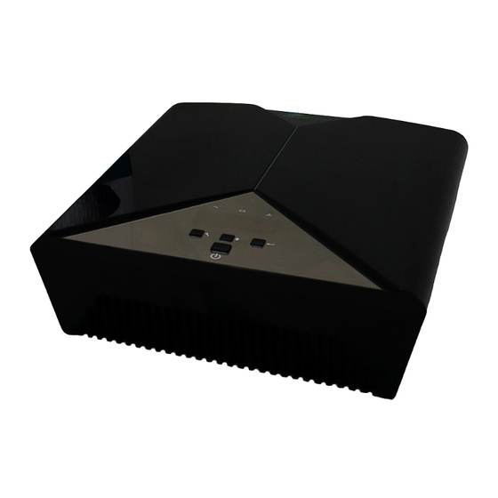
1.1 Product Outlook Front Panel ① Power ON/OFF button ② Setting function button ③ LCD ④ LED indicators Rear Panel ① AC input socket ② AC output socket ③ PV Input terminals ④ Battery terminals ⑤ DC Fan... - Page 7 LCD Display LCD displays the power flow and input/output readings in a visualized graphic design which allows the user to understand the operation status easily. The backlight of LCD remains on whenever the inverter is working (including Standby Charging Mode and Fault Mode). Icon Description This icon is showed when AC input (from AC mains or generator) presents.
- Page 8 LED Indicators The operation mode of the inverter can be easily told by LED indicators. Please see the table below for details. LED indicators Information Green Line Mode 1 (charge Green flashing every 2 seconds current >3A) Line Mode 2 (charge Green solid lighting current 3A) Green flashing as cycle:...
-
Page 9: Typical Application
1.2 Typical Application A typical application diagram for home and office applications is as shown below. The inverter can accept AC input from AC mains, and is capable of supply various loads such as fluorescent lamp, fan. -
Page 10: Installation
INSTALLATION 2.1 Safety Clearance The minimum clearance to the wall shall be larger than 30cm in order to ensure proper ventilation. In the event the ambient temperature is high, it's recommended to increase the distance of safety clearance to improve the heat dissipation. 2.2 Mounting Inverter on the Wall The inverter is designed to either be placed on horizontal surface or be mounted on the wall with various ways (as shown below). - Page 11 Connect the battery cables • The gauge of battery cables shall be no less than 6 AWG with 105*C rating. • No matter how the batteries are connected (in series or in parallel), make sure the cables' terminal voltage is consistent with the inverter's specification (12V for 1000VA/1200VA model and 24V for 2000VA/2200VA model).
-
Page 12: Pv (Solar) String
The user may connect the batteries in series in order to double the voltage connected to inverter. The diagram below illustrates how to connect two 12V batteries in series to make up 24V (for 2000VA/2200VA model) The user may connect the batteries in parallel in order to increase the total battery capacity without changing the battery voltage. -
Page 13: Connect Ac Input Cables And Loads
To ensure better contact and reliability, ring terminal shall be fit on the cables from PV string before connecting to the inverter. The recommended size of ring terminal Ring Terminal Model Wire Gauge Dimensions Cable mm² D(mm) L(mm) 1K/1.2K/2K/2.2K 1*10AWG 5.16 19.8 Connect the cables from PV string to PV input terminals as shown below, a circuit... - Page 14 B. ”tWIDE” setting: Set the selector to "WIDE" when connected with loads which are less sensitive on voltage range (e.g. light bulb, fan, fluorescent tube). With this setting, the inverter's input voltage range is extended to 90~280VAC while output voltage follows input voltage.
-
Page 15: Operation
OPERATION After connecting batteries, AC input cables, and loads, the inverter is now ready to work. 3.1 Standby Charging Mode The battery can be charged without switching on the inverter, and such operation is called Standby Charging Mode. When AC input cable and battery is connected, the inverter will enter Standby Charging Mode and LCD will be turned on with the following display. -
Page 16: Operation Modes (After Powered On)
3.2 Operation Modes (after powered on) Press the Power ON/OFF button to power on the inverter and the inverter will automatically enter either of the operation mode according to the condition of LINE MODE1 AC input power is present but there is no PV power (e.g. nighttime). Load is supplied by AC input power directly. -
Page 17: Priority Setting Switch
3.3 Priority Setting Switch In LINE MODE 2, if priority setting switch is set to give PV priority and PV power is also strong enough to support load, the AC input will not be consumed even though it is present. This is deemed an energy-saving operation. BACKUP MODE 1 Both AC input and PV input are absent. -
Page 18: Fault Mode
BACKUP MODE 3 AC input is absent and PV power is strong enough to not only support the load and charge the battery. If the PV power persists, the load can be powered continuously without consuming power from battery. 3.4 Fault Mode Inverter enters Fault Mode when there is a fault event. - Page 19 Selectable option & behavior Program Description LCD setting display Wide(default): if selected, acceptable AC input voltage range will be within AC input voltage 90-280VAC range Narrow: If selected, acceptable AC input voltage range will be within 170-280VAC Solar first(default): solar energy provide power to the loads as first priority.
- Page 20 Only solar: Solar energy will be the only charger source no matter utility is available or not. Setting voltage point back to Options in 1K/1.2KVA model: battery mode Full/12.5V/13V/13.5V(default)/14.0V when selecting Options in2K/2.2KVA model: "SBU priority" or" Full/25V/25.5V/26V/26.5V/27V(default)/ Solar first- In 27.5V/28V.
- Page 21 Restart enable: When unit is overloaded, overload alarm 5 seconds and turn off output for 15 seconds, then restart unit again. The restart cycle Is 5 times. Auto(default): If setting auto, low DC cut off voltage will be related to load percent. 10.0V for 12V model @>=60%load 10.5V for 12V model <60%load 20.0V for 24V Low DC cut off...
-
Page 22: Specification
4. SPECIFICATION MODEL AV-1018SCC AV-1218SCC AV-2018SCC AV-2218SCC CAPACITY VA/W 1000VA/800W 1200VA/1000W 2000VA/1600W 22OOVA/18OOW NORMAL BATTERY VOLTAGE 12Voc 24Voc 24VDC LINE MODE INPUT Normal Voltage 230VAC Voltage Range 170~280VAC (Narrow Range) 90~280VAC (Wide Range) Normal Frequency 50hz or 60Hz OUTPUT Voltage 230Vac Frequency Following the Utility... -
Page 23: Troubleshooting
TROUBLESHOOTING Problem Possible Cause Remedial Action No LCD display Battery voltage is low Re-charge the battery and check if the battery cables are well- connected Battery is defective Replace the batteries Power button is not pressed Press and hold the power button Mains are normal but works in backup AC input is absent Check the connection of AC input... -
Page 24: Alarm Behavior Table
APPENDIXA How to Select and Configure PV Panels The following parameters can be found in each PV panel's specification: • Pmax:Max output power (W) • Vmp:Max power voltage (V) • Voc:open-circuit voltage (V) • Imp:Max power current (A) • lsc:short-circuit current (A) PV panels can be connected in series or parallel in order to obtain the desired output voltage and current which meets the inverter's allowed range. -
Page 25: Appendixa
• Total Vmp of the string shall be within the operating voltage range of solar battery charger (16~18V for 1000VA/1200VA model and 32~36Vfor 2000VA/2200VA model are recommended). • Total Imp of the string shall be less than the max. charging current of the solar battery charger (50A for 1000VA/2000VA and 60A for 1200VA/2200VA model) •... - Page 26 (4) Check again the Voc and Isc of PV string, Voc of string is 21.6V < 55V (Max. PV Input Voltage) =>OK Isc of string is 6x8.75A = 52.5A < 65A(Max. PV Input Current) =>OK Example 2 - How to connect 1200VA model to PV panels with the following parameters? •...
- Page 27 Example 3 -How to connect 2000VA model to PV panels with the following parameters? • Pmax:250W • Vmp:30.96V • Voc:36.6V • lmp:8.07A • lsc:8.75A (1) Max. charging current is 50A, 50A/8.07A = 6.19=>max. Number of PV panel in parallel is 6. (2) Operating Voltage Range is 32~36V, One PV panel Vmp 30.96V is between 32~36V =>...
- Page 28 Example 4 - How to connect 2200VA model to PV panels with the following parameters? • Pmax:250W • Vmp:30.96V • Voc:36.6V • Imp:8.07A • lsc:8.75A (5) Max. charging current is 60A, 60A/8.07A = 7.43 => max. Number of PV panel in parallel is 7. (6) Operating Voltage Range is 32~36V, One PV panel Vmp 30.96V is between 32~36V =>...
- Page 29 APPENDIX B HOW TO DETERMINETHE OUTPUT SOURCE PRIORITY SETTING AND CHARGER SOURCE PRIORITY SETTING? Please read this document carefully if you intend to manually set the priority setting of the product. Improper setting might compromise the function and performance of the product. The product is designed to accept both utility and solar (PV) power as input source, and it also provides a function allowing the user to determine the priority between utility and solar input power.
- Page 30 2. Setting solar as priority 2.1 When utility is normal If solar power is strong enough to support the load, utility power will not be consumed even though it’s available. If solar power is not enough, battery will firstly come up to support the loads, and after battery is low or the setting point in program 5, utility will then take over to support the loads, if solar is absent, utility will then take over to support the load too.
- Page 31 B. Charger source priority setting 1. Setting Utility as charger source priority Utility first: Utility will charge battery as priority. Solar energy will charge battery only when utility power is not available. 2. Setting solar as charge source priority Solar energy will charge battery as priority. Utility will charge battery only when solar energy is not available 3.
Need help?
Do you have a question about the SICM8H12 and is the answer not in the manual?
Questions and answers
Good day. My inverter has a long beep that doesn’t stop when I turn it on all of a sudden and the warning light is on. What is it that’s causing this? It’s about 2 years old and I recently replaced the batteries.