Table of Contents
Advertisement
Quick Links
Advertisement
Table of Contents

Summary of Contents for Datcon DT1400 Series
- Page 1 DT1400 xx xx Limit switch Operating Instructions...
-
Page 2: Table Of Contents
DT1400 xx xx Contents 1. About this document .............4 1.1. Function ................... 4 1.2. Target group................4 1.3. Symbolism used............... 4 2. For your safety ...............5 2.1. Authorized personnel ............... 5 2.2. Appropriate use................ 5 2.3. Warning about misuse ............. 5 2.4. - Page 3 DT1400 xx xx 7. Setting-up ..............24 7.1. Typing the code (password) in ..........24 7.2. The menu structure ..............26 7.3. Display brightness (01. menu item)........27 7.4. Input selection (02. menu item)..........28 7.5. Decimal point position (03. menu item)........30 7.6.
-
Page 4: About This Document
DT1400 xx xx 1. About this document 1.1. Function This operating instructions manual has all the information you need for quick set-up and safe operation of DT1400 xx xx. Please read this manual before you start setup. 1.2. Target group This operating instructions manual is directed to trained personnel. -
Page 5: For Your Safety
For safety and warranty reasons, any internal work on the instruments must be carried out only by DATCON personnel. 2.2. Appropriate use The DT1400 xx xx Limit switch enable process variable 0-20 mA, 4-20 mA, 0-10 V, 0-5 V, 2-10 V to be displayed in engineering units on the control panel. -
Page 6: Product Description
DT1400 xx xx 3. Product description 3.1. Delivery configuration Delivered items The scope of delivery encompasses: • DT1400 xx xx • documentation: this operating instructions manual warranty 3.2. Type designation 3.3. Operating principle Area of application The DT1400 xx xx Limit switch compares the 0-20 mA, 4-20 mA, 0-10 V, 0-5 V, 2-10 V input signal with the set values. -
Page 7: Adjustment
DT1400 xx xx Oparating principle The input current or voltage to be measured is led to the 22 bit A/D converter through a protection and signal condition circuit. The digital output signal of the A/D converter is processed by a microcontroller. The microcontroller drives the 5 digit LED display, processes the front panel membrane keypad, drives the limit relays, the analogue output. -
Page 8: Display, Indicators
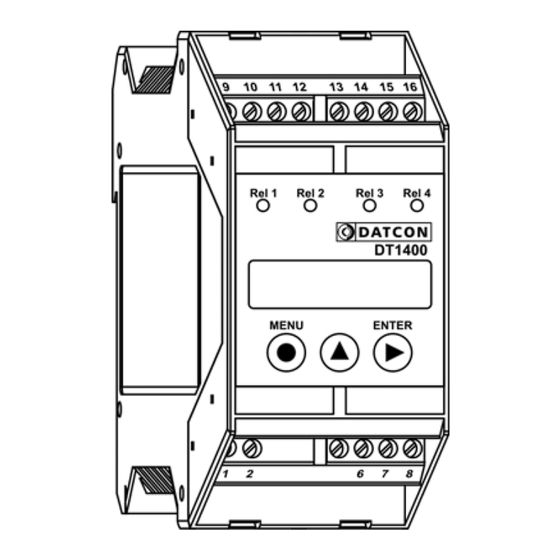
DT1400 xx xx 3.5. Display, indicators The following figure shows the front panel of the instrument: 1. „Rel1” yellow indicator for indicating that limit output 1 is in “on-state” (LIMIT1). „Rel2” yellow indicator for indicating that limit output 2 is in “on-state”... -
Page 9: Mounting
DT1400 xx xx 4. Mounting 4.1. General instructions The instrument should be installed in a cabinet with sufficient IP protection, where the operating conditions are in accordance with chapter 10.1. Technical specification, as described under the title: Operating conditions. Mounting position The instruments are designed in housing for mounting on TS-35 rail. -
Page 10: Mounting
DT1400 xx xx 4.3. Mounting The following figure shows the mounting procedures (fixing on the rail): Mounting on the rail The mounting doesn’t need any tool. 1. Tilt the instrument according to the figure; put the instrument’s mounting hole onto the upper edge of the rail (figure step 1.). -
Page 11: Connecting
DT1400 xx xx 5. Connecting 5.1. Preparing the connection Always observe the following safety instructions: • Connect or disconnect only in the complete absence of line voltage • Take note the data concerning on the overcurrent protection in installation. • Use only a screwdriver with appropriate head Select connecting Take note the suitability of the connecting cable... -
Page 12: Connecting The Power Supply And The Input Signal
DT1400 xx xx 5.2. Connecting the power supply and the input signal The following figure shows the wiring plan, connecting the DT1400 xx xx to the power supply and to the input signal: Wiring plan, connecting the instrument to the power supply and to the input signal (see also “Application... -
Page 13: Connecting The Rel 1, 2 Limit Relay Outputs
DT1400 xx xx 5.3. Connecting the Rel 1, 2 limit relay outputs The following figure shows the wiring plan, connecting the limit relay outputs: Wiring plan, connecting the Rel 1, 2 limit relay outputs (see also “Application example”) 1. Loosen terminal screws. 2. -
Page 14: Connecting The Rel 3, 4 Limit Relay Outputs (Option)
DT1400 xx xx 5.4. Connecting the Rel 3, 4 limit relay outputs (option) The following figure shows the wiring plan, connecting the optional limit relay outputs: Wiring plan, connecting the Rel 3, 4 limit relay outputs (see also “Application example”) 1. -
Page 15: Connecting The Analogue Output (Option)
DT1400 xx xx 5.5. Connecting the analogue output (option) The following figure shows the wiring plan, connecting analogue output in case of active (DT1400 RL2 IA, DT1400 RL2 IA PS) or passive (DT1400 RL2 IP, DT1400 RL2 IP PS) output: Wiring plan, connecting the analogue output (see also “Application... -
Page 16: Connecting The Transmitter Power Supply (Option)
DT1400 xx xx 5.6. Connecting the transmitter power supply (option) The following figure shows the wiring plan, connecting transmitter power supply (DT1400 RL2 TS, DT1400 RL2 TS PS): Wiring plan, connecting the transmitter power supply (see also “Application example”) Be careful the polarity of the cables. -
Page 17: Display And Manual Controls
DT1400 xx xx 6. Display and manual controls 6.1. The first start-up The display The display is indicated by the arrow (1) The factory default setting is: Selected input signal: 4-20 mA Scaling: 4 mA ÷ 20 mA ÷ 100% ... -
Page 18: Characters And Mnemonics Appearing On The Display
The right-side column gives first the meaning, then the full English word in brackets and, after the hyphen, and explanation may be given. Login text DT - Datcon instrument 1400 - Type of the instrument Two limit relay output ... - Page 19 DT1400 xx xx Error messages Low (Error: LOW Input signal) Reason of error: the input signal is under of the measuring range. For example: the selected input mode is 4-20 mA and the input signal is 0 mA. A/D underflow (Error: AD Underflow) ...
- Page 20 DT1400 xx xx During code writing Code? (Code) - type in the code! Bad code (Bad Code) A User login took place (User) A Supervisor login took place (Supervisor) During setting The typed number is lower than allowed (Low Limit) ...
-
Page 21: Manual Controls, Display, Indicators
DT1400 xx xx 6.3. Manual controls, display, indicators DT1400 xx xx can be adjusted by the membrane push- buttons indicated by (1), (2), and (3) in the drawing. Functions of the push-buttons during measurement (1) MENU button: Entering the menu When you push this button, the instrument will ask for a password (code) in accordance with Chapter 7.1. - Page 22 DT1400 xx xx 2. Keeping the button pressed down, after 1.5 sec the minimum value will be displayed as long as the button is pressed down. 3. Press the ▲ button second time as long as you see this: The mnemonic indicates that it will be displayed the maximum value measured after the last clear.
- Page 23 DT1400 xx xx Indicators The following figure shows the 4 yellow indicator on the left side of DT1400 xx xx front panel: (1) Rel 1: limit output indicator (yellow) indicates that the limit output 1 is in “on-state” (LIMIT1). (1) Rel 2: limit output indicator (yellow) indicates that the limit output 2 is in “on-state”...
-
Page 24: Setting-Up
DT1400 xx xx 7. Setting-up 7.1. Typing the code (password) in The importance of the You may enter the menu only after you have typed your code code in. The code is made from 3 numeric characters. This solution prevents unauthorised persons from changing the settings of the instrument. - Page 25 DT1400 xx xx Automatic exit from If no buttons are pressed, the instrument displays the the request for the code mnemonic (Auto Escape) after 4 minute has passed from the last pressing of a button, and it RESTARTS, i. e. goes back to the measuring mode. This solution is due to security: unauthorised persons, after 4 minute, will not be able to change the settings of the instrument, should it be left alone for some reason.
-
Page 26: The Menu Structure
DT1400 xx xx 7.2. The menu structure 01: Display brightness 27. page 02: Input selection 28. page 03: Decimal point position 30. page 04: Low value of scale 31. page 05: High value of scale 33. page 06: Leading zeroes enable / disable 35. -
Page 27: Display Brightness (01. Menu Item)
DT1400 xx xx 7.3. Display brightness (01. menu item) Function The brightness can be set between 10%-100%, in 10% steps. [factory default: 100%] Sequence of operations 1. Enter the menu by the user or the supervisor code. Chapter 7.1. Typing the code in describes how you can type the code in. -
Page 28: Input Selection (02. Menu Item)
DT1400 xx xx 7.4. Input selection (02. menu item) Function The instrument has current and voltage inputs. Here you can select the input and the signal level. [Factory default: 4-20 mA current input] Sequence of operations 1. Enter the menu with the supervisor code. The way the code should be type in can be found in Chapter 7.1. - Page 29 DT1400 xx xx Exit from the menu item 1. After finishing the settings, press the MENU button to exit from the given menu item, and you see: (2. If you want to change the settings you have done just now, or if you just want to check what you have typed in, go on with the operation from point 3 of the Sequence of operations.)
-
Page 30: Decimal Point Position (03. Menu Item)
DT1400 xx xx 7.5. Decimal point position (03. menu item) Function Setting the position of the decimal point on the display, or switching the decimal point off. [Default factory setting: 2 decimals] Sequence of operations 1. Enter the menu with the supervisor code. The way the code should be type in can be found in Chapter 7.1. -
Page 31: Low Value Of Scale (04. Menu Item)
DT1400 xx xx 7.6. Low value of scale (04. menu item) Function Any optional display range can be assigned to the input signal range (scaling). Here you can set the low value of the desired display range. [Factory default: 000.00. ] Note! For scaling the DISPLAYED value you should set the high value also. - Page 32 DT1400 xx xx Exit from the menu item 1. After finishing the settings, press the MENU button to exit from the given menu item, and you see: (2. If you want to change the settings you have done just now, or if you just want to check what you have typed in, go on with the operation from point 3 of the Sequence of operations.)
-
Page 33: High Value Of Scale (05. Menu Item)
DT1400 xx xx 7.7. High value of scale (05. menu item) Function Any optional display range can be assigned to the input signal range (scaling). Here you can set the high value of the desired display range. [Factory default: 100.00. ] Note! For scaling the displayed value you should set the low value also. - Page 34 DT1400 xx xx Exit from the menu item 1. After finishing the settings, press the MENU button to exit from the given menu item, and you see: (2. If you want to change the settings you have done just now, or if you just want to check what you have typed in, go on with the operation from point 3 of the Sequence of operations.)
-
Page 35: Enable / Disable Displaying The Leader Zeros (06. Menu Item)
DT1400 xx xx 7.8. Enable / disable displaying the leader zeros (06. menu item) Function Leader zero: the zeros that stand in front of an integer of no value. E.g. the instrument displays the value 5.2 together with the leader zeros: ... - Page 36 DT1400 xx xx Exit from the menu item 1. After finishing the settings, press the MENU button to exit from the given menu item, and you see: (2. If you want to change the settings you have done just now, or if you just want to check what you have typed in, go on with the operation from point 3 of the Sequence of operations.)
-
Page 37: Rounding Displayed Value (07. Menu Item)
DT1400 xx xx 7.9. Rounding displayed value (07. menu item) Function In some case it can be useful to round the displayed value. E.g. the measured physical quantity is noisy. In this menu item you can select a rounding value. Sequence of operation 1. -
Page 38: The Number Of Averaged Measurements (08. Menu Item)
DT1400 xx xx 7.10. The number of averaged measurements (08. menu item) Function The instrument performs cca. 12 measurements in each seconds. The displayed measurement result is generated as the average of several measurements. Here you can define the number of measurements that should be used for calculating the averaged numerical value. - Page 39 DT1400 xx xx Exit from the menu item 1. After finishing the setting, press the MENU button, to exit from the menu item, and you see this: (2. If you want to change the setting you have done just now, or if you just want to check what you have typed in, go on with the operation from point 3 of the Sequence of operations.)
-
Page 40: Display Refresh Time (09. Menu Item)
DT1400 xx xx 7.11. Display refresh time (09. menu item) Function The instrument performs cca. 12 measurements in each seconds. It’s too fast to see the changing of the measurement value. Here you can define the time periods by which the instrument displays the new measurement values. -
Page 41: Setting Limit Outputs (10., 11., 12., 13. Menu Item)
DT1400 xx xx 7.12. Setting limit outputs (10., 11., 12., 13. menu item) Function The instrument has two (RL2) or four (RL4) limit outputs. They are identical with each other, and work independently. Operation: the instrument keeps comparing the displayed physical value with the (adjustable) limit value. - Page 42 H.LI, than the state of limit output doesn’t change. This operating mode is used in other DATCON instruments. Here you can use it at any control task where the physical value is the process value and you can control the process through the limit outputs.
- Page 43 DT1400 xx xx Low limit value 8. Keep stepping by pressing the ▲ button as long as you Sequence of operations see this sub-menu item: (Limit1 Low Limit = = limit 1, low limit value). Here you can define the numerical value by which the device will compare the measured physical values.
- Page 44 DT1400 xx xx View of the used terms The figure shows the limit output change vs. input signal, where the value of hysteresis is > 0. Remark: this operation is working in the mode: Setting the hysteresis 17. Enter by pressing the ENTER button. value ...
- Page 45 DT1400 xx xx High limit value 23. Keep stepping by pressing the ▲ button as long as you Sequence of operation see this sub-menu item: (Limit1 High Limit = limit 1, high limit value). Here you can define a second numerical value with which the instrument will compare the displayed ...
- Page 46 DT1400 xx xx Limit output hold mode In case of basic operating mode the limit output is switching on or switching off when the conditions are exist. In limit output hold mode the output is kept in switched state and only by pressing ENTER button can be reset (limit signaling acknowledge).
-
Page 47: Limit Output State Display Mode (14. Menu Item)
DT1400 xx xx 7.13. Limit output state display mode (14. menu item) Function The state of limit outputs may present on the display. Here you can set the condition of presenting the states. [Factory default: dynamic] Sequence of operations 1. Enter the menu by typing the user or supervisor code. The way the code should be type in is described in Chapter ... - Page 48 DT1400 xx xx Sequence of operations • (On = switched on) It displays the limit output state continuously. Keeping the ENTER button pressed it displays the measuring value. • (Off = switched off) There is no limit output display. Remark: Independent from the limit output state display mode the front panel indicators always signal the limit output states.
-
Page 49: Clear Minimum And Maximum Values (15. Menu Item)
DT1400 xx xx 7.14. Clear minimum and maximum values (15. menu item) Function To clear the measured and stored mimimum and maximum values. Sequence of operations 1. Enter the menu by typing the supervisor code. The way the code should be type in is described in Chapter 7.1. -
Page 50: Analoge Output Signal Setting (16. Menu Item)
DT1400 xx xx 7.15. Analoge output signal setting (16. menu item) Function In this menu item you can choose between 4-20 mA and 0-20 mA output current. [Factory default: 4-20 mA] Sequence of operations 1. Enter the menu by typing a supervisor code. The way the code should be type is described in Chapter ... -
Page 51: Assignment Analog Output Low (Start) Value To Display Value (Scaling) (17. Menu Item)
DT1400 xx xx 7.16. Assignment analog output low (start) value to display value (scaling) (17. menu item) Function Here you can assign analog output start value (0 mA or 4 mA) to the measured physical value. This way you can assign any phisical range to any output range. [Factory default: 0.00 so in case of a measured value 0.00 the output value will be 4 mA (or 0 mA).] Notice! For scaling the analog output must be assign the... - Page 52 DT1400 xx xx Exit from the menu item 1. After finishing the setting, press the MENU button, to exit from the menu item, and you see this: (2. If you want to change the setting you have performed just now, or if you just want to check what you have typed in, continue the operation from Point 3 of the Sequence of operations.) (3.
-
Page 53: Assignment Analog Output High (End) Value To Display Value (Scaling) (18. Menu Item)
DT1400 xx xx 7.17. Assignment analog output high (end) value to display value (scaling) (18. menu item) Function Here you can assign analog output high value (20 mA) to the measured physical value. This way you can assign any phisical range to any output range. [Factory default: 100.00 so in case of a measured value - 100.00 the output value will be 20 mA.] Notice! For scaling the analog output must be assign the... - Page 54 DT1400 xx xx Exit from the menu item 1. After finishing the setting, press the MENU button, to exit from the menu item, and you see this: (2. If you want to change the setting you have performed just now, or if you just want to check what you have typed in, continue the operation from Point 3 of the Sequence of operations.) (3.
-
Page 55: Tests (19. Menu Item)
DT1400 xx xx 7.18. Tests (19. menu item) Function Testing the display, the digital outputs and the analog output. Display test 1. Enter the menu by typing either the user code or the Sequence of operations supervisor code. The way the code should be type in is described in Chapter ... - Page 56 DT1400 xx xx Digital (relay) output test 8. Keep stepping by pressing ▲ button as long as you see Sequence of operations this menu item: (Test: Digital Output = digital output test). 9. Enter the menu item by pressing the ENTER button. ...
- Page 57 DT1400 xx xx Exit from menu item 1. Press the MENU button, to exit from the menu item, and you see this: (2. If you want to make further testing, continue the operation from Point 3 of the Sequence of operations.) (3.
-
Page 58: Changing The User Code (20. Menu Item)
DT1400 xx xx 7.19. Changing the user code (20. menu item) Function You can define new codes instead of the factory-defined user code. The code is an optional number within the range between 0000 and 9999. [Default factory setting: 0000] Sequence of operations 1. - Page 59 DT1400 xx xx Sequence of operations Warning! Do not forget the user code you have defined. If you forget it, defining another one is possible only by using a supervisor code for entering into the menu. Exit from the menu item 1. As you have already left the menu item there is no need further settings.
-
Page 60: Changing The Supervisor Code (21. Menu Item)
DT1400 xx xx 7.20. Changing the supervisor code (21. menu item) Function You can define new codes instead of the factory-defined supervisor code. The code is an optional number within the range between 0000-9999. [Default factory setting: 1000] Sequence of operations 1. Enter the menu by typing the supervisor code. The way the code should be type in is described in Chapter ... - Page 61 DT1400 xx xx Sequence of operations Warning! Do not forget the supervisor code you have defined. If you forget it, defining another one is possible in the service only. Exit from the menu item 1. As you have already left the menu item there is no need further settings.
-
Page 62: Resetting The Default Settings (22. Menu Item)
DT1400 xx xx 7.21. Resetting the default settings (22. menu item) Function In this case all the settings are deleted, and the default factory setting is restored. Using this function makes sense in that case, when the settings of the instrument have changed so much, that it is easier to start the setting-up process from the default factory setting. -
Page 63: Fault Rectification
DATCON personnel. In the case of errors, it is recommended to notice of the displayed error message, as well as of the phenomenon seen. These information please communicate to the Datcon service personnel. 20170920-V0... -
Page 64: Dismounting
DT1400 xx xx 9. Dismounting 9.1. Dismounting procedure Before dismounting take note the warnings written in Chapter 5.1. The following figure shows the dismounting procedures: Dismounting from the rail The dismounting procedure needs a screwdriver for slotted screws. 1. Before dismounting disconnect all wires. 2. -
Page 65: Appendix
DT1400 xx xx 10. Appendix 10.1. Technical specifications Power supply Supply voltage: DT1400 xx xx: 18-40 V DC / 14-29 V AC DT1400 xx xx PS: 140-250 V AC / 180-250 V DC Power consumption: 3.5 W / 3 VA Input parameters Input signal: DC current / DC voltage... - Page 66 DT1400 xx xx Limit outputs Output type: 2 NO SPST relays Contact rating: 30 VDC, 3 ADC / 240 VAC, 3 AAC Refreshing time: Equal dispaly refreh time Limit outputs (optional) Output type: 2 NO SPST relays Contact rating: 30 VDC, 3 ADC / 240 VAC, 3 AAC Refreshing time: Equal dispaly refreh time Active analog output (optional)
- Page 67 DT1400 xx xx Ambient conditions Operating temperature range 0 °C - +60 °C (-20 °C - +60 °C on request) Storage temperature range -25 °C - +70 °C Climatic conditions: EN 60654-1, class B2 Relative humidity: 90% (max., non-condensing) Place of installation: Cabinet Electromagnetic compatibility (EMC) In accordance with the standard EN 61326-1:2006...
-
Page 68: Application Example
DT1400 xx xx 10.2. Application example Analog output option: 20170920-V0... - Page 69 DT1400 xx xx RL4 option: 20170920-V0...
- Page 70 DT1400 xx xx TS option: 20170920-V0...
- Page 71 DT1400 xx xx 20170920-V0...
Need help?
Do you have a question about the DT1400 Series and is the answer not in the manual?
Questions and answers