
Related Manuals for Albiral ARTHUR HOLM DynamicX2Talk

Summary of Contents for Albiral ARTHUR HOLM DynamicX2Talk
- Page 1 User Guide DynamicX2Talk HDCP compliant retractable monitors for furniture integration with integrated DynamicTalk Technology Serving Desing Danish craftmanship Mediterranean soul...
-
Page 3: Table Of Contents
TABLE OF CONTENTS EC REGULATIONS AND SECURITY SAFETY INSTRUCTIONS SYSTEM DESCRIPTION CONTROLS OSD MENU INPUT CONNECTORS DYNAMICTALK HANDLING AHLINK INPUT SIGNALS AHNET PROTOCOLS INFORMATION ON DISPOSAL WARRANTY TERMS AND CONDITIONS... - Page 4 Please, read this installation and operating instructions carefully and keep them in a safe place for future reference. We remain at your entire disposal if you have any suggestions that would help us improve our products. Henrik Holm General Manager hholm@albiral.com...
- Page 5 ABOUT US The Company Arthur Holm has its origins in the Danish furniture designer Jorgen Alex Jensen, who was active during the sixties and the seventies. His design inspiration and his concept of ergonomics have been continued by his family, who is the design force behind Arthur Holm product range. The result of combining Scandinavian design tradition with Mediterranean creativity, flexibility and emotion is a wide product range built on more than 25 years of craftsmanship.
-
Page 6: Ec Regulations And Security
EC REGULATIONS AND SECURITY ATTENTION: Do not disassemble or modify the device in any way. This symbol warns of the presence of dangerous un-insulated voltages inside some of the components, of sufficient magnitude to expose people to risk of electronic shock. This symbol draws attention to important use and maintenance instructions in the manual that accompanies the unit. - Page 7 SAFETY INSTRUCTIONS Wiring connected to hazardous voltage requires installation by qualified personnel or the use of ready-made flexible cables. For your security, your equipment must be connected to an elec- trical outlet with grounding connection protection. Since the plug is used to disconnect the device, the operating electrical outlet must be in an easily accessible place.
-
Page 8: System Description
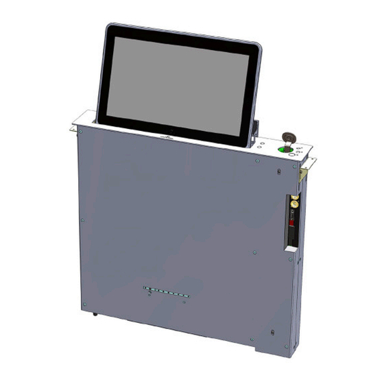
SYSTEM DESCRIPTION Applications DThe DynamicX2Talk system is a professional TFT display with DynamicTalk and an electrical lift system for installation into a horizontal furniture surface. The DynamicTalk system is a universal motorized microphone lift system remotely controllable through RS422 or GPI with Dynamic LED Ring for “Ready to Talk”... -
Page 9: Controls
CONTROLS OSD MONITOR CONTROL The OSD buttons, to control or configure the monitor, are located at the lower body housing of the system POWER Switch ON/OFF the monitor. Indicates operation status. SOURCE Signal input selection. LEFT Cursor control left on the OSD menu. RIGHT Cursor control right on the OSD menu. - Page 10 CONTROLS Remote IR control POWER Switch ON/OFF the monitor MENU Activates the OSD menu on screen Cursor control up on the OSD menu DOWN Cursor control down on the OSD menu LEFT Cursor control left on the OSD menu RIGHT Cursor control right on the OSD menu Selects the function on the OSD menu.
- Page 11 CONTROLS IR sensor The IR sensor is located on the lower right side of the screen. Monitor movement controls On the upper cover plate, there are two buttons to control the UP and DOWN monitor movements and three buttons to control the DynamicTalk functions and to external control other devices (GPO).
-
Page 12: Osd Menu
CONTROLS Monitor movement controls 5. - Conference mode: In conference mode the microphone is controlled by the external conference system. In this case, ths button then, has no function and the contact close of the push button is present on the SubD9 control connector (GPO). - Page 13 OSD MENU Screen Input: Input signal selection ∙ DVI-A ∙ DVI 1 ∙ DVI 2 ARC: Adjusts the image aspect on screen ∙ Full The image is showed on full screen ∙ 16:9: Shows the image on screen with 16:9 aspect ∙...
- Page 14 OSD MENU Setup Language: OSD language selection ∙ PC CONTROL: Adjust the image on screen. Only on ARGB (analogue) input ∙ H-POS: Adjust the image on screen horizontally ∙ V-POS: Adjust the image on the screen vertically ∙ PHASE: Adjust the phase ∙...
-
Page 15: Input Connectors
INPUT CONNECTORS DVI 1/DVI A: DVI-I input signal. Connect a DVI (digital) input signal and select DVI 1 on the OSD monitor menu. Use a DVI to VGA adapter to connect an ARGB (analogue) input signal and select DVI-A on the OSD monitor menu DVI 2: DVI-D input signal. - Page 16 INPUT CONNECTORS MICROPHONE INPUT CONNECTORS Microphone out: XLR3 microphone connector installed DynamicTalk 12V D.C.: Power supply input connector. XLR-4 connector: 1,2: Ground 3,4: 12Vdc GPI: SubD 9 pins female connector to contact close external functions COMMAND FUNCTION Contact close of the customised push button on upper cover plate (middle button).
- Page 17 INPUT CONNECTORS MICROPHONE INPUT CONNECTORS Settings: 6 dip switch to configure the DynamicTalk. DIP SWITCH FUNCTION ON: Dynamic Talk configured in PA mode. The T push button controls the microphone mute function. 1,2,3 OFF: DynamicTalk configured in conference mode. The TALK push button has no function, the contact close is available on GPO connector and the LED ring is controlled externally (GPI).
- Page 18 INPUT CONNECTORS MICROPHONE LENGTH SETTING PROCEDURE DynamicTalk is designed to work with microphones of different lengths. Twosigns to identify an incorrect setup of the microphone length are: - The microphone do not goes down completely. - The microphone goes down too slowly and gets stuck inside. The microphone length can be adjusted using the Monitor Configurator Tool, but there is also a quick procedure that doesn’t require the use of a PC or cable:...
-
Page 19: Dynamictalk Handling
DYNAMICTALK HANDLING Please follow the figure below for a correct product usage of the DynamicTalk microphones. To avoid any product malfunctions, do not attempt to bend the microphone to the incorrect angle or outside the microphone's working area, as indicated on the picture below. Please note that ware to the microphone and pop screen surface can occur. - Page 20 DYNAMICTALK HANDLING Before connecting the monitor, open the hatch and remove the 2 foam protection pieces. Do not use the unit in horizontal position. It could damage the mechanical parts of the monitor. Do not use force to open or close the monitor. It could damage the mechanical parts of the monitor.
-
Page 21: Ahlink
AHLINK AHlink is used to control and set-up the unit. By default, the AHlink signal on the unit is deactivated. To activate the AHlink signal, press for 5 seconds the external Up and Down screen buttons located on the cover plate, or press for 5 seconds the UP and Down contact close on the GPI connector. - Page 22 AHLINK If the device does not appear on the window, the AHlink signal is not active. AHlink name always begins with AH characters and the fourth last MAC AHlink address. Select the device to control and set-up the unit. When selecting device, the first page will upload...
- Page 23 AHLINK SERIAL Serial number of the unit Firmware version Controls the Up and Down screen movements DISP: Turns the display ON or OFF DVIA, DVI1, DVI2: Input source selection BACKL: Configuration of the display's backlight CONTR: Configuration of the display's contrast BRIGHT: Configuration of the display's brightness...
-
Page 24: Input Signals
INPUT SIGNALS AH17D X2HDGA TALK/ AH22D X216GA TALK RESOLUTION Horizontal freq (KHz) Vertical freq (Hz) Scanning type 800x600@60Hz 37.879 60.317 Progressive 800x600@72Hz 48.077 72.188 Progressive 800x600@75Hz 46.875 75.000 Progressive 1024x768@60Hz 48.363 60.005 Progressive 1024x768@70Hz 56.476 70.070 Progressive 1024x768@75Hz 60.023 75.030 Progressive 1280x720@60Hz 44.697 59.915 Progressive 1360x768@60Hz 47.720 59.799... - Page 25 AHNET PROTOCOL Wiring Diagram 1. Data TX + 2. Data TX – 3. Data RX + 4. NC 5. NC 6 .Data RX RJ-45 7. NC 8. NC Connection PINS 1 & 2 The units respond PINS 3 & 6 The units receive instructions Protocol to control the unit by addressable RS422 bus.
- Page 26 AHNET PROTOCOL Commands COMMAND DESCRIPTION RESPONSE GO UP FB XX 01 01 00 FA XX 01 01 00 GO DOWN FB XX 01 01 00 FA XX 01 00 00 BUTTON LOCK FB XX 04 01 00 FA XX 04 01 00 BUTTON UNLOCK FB XX 04 00 00 FA XX 04 00 00 FA XX 14 00 INQUIRY CONTROL BYTE FB XX 14 CB1 FA XX 02 01 00...
- Page 27 AHNET PROTOCOL Communications protocol Speed and configuration BAUD RATE 38400 COMMUNICATION RS422 DATA BITS CONNECTION RJ45 PARITY NONE WIRING CAT-5 STOP BITS Wiring Diagram 1. Data TX + 2. Data TX – 3. Data RX + 4. NC 5. NC 6 .Data RX RJ-45 7.
- Page 28 AHNET PROTOCOL Commands COMMAND DESCRIPTION RESPONSE GO UP FA XX 01 01 00 FB XX 01 01 00 GO DOWN FA XX 01 00 00 FB XX 01 01 00 MUTE ON (Only in PA mode) FA XX 02 00 00 FB XX 02 01 00 MUTE OFF (Only in PA mode) FA XX 02 00 FB XX 02 00 00 BUTTON LOCK...
-
Page 29: Information On Disposal
INFORMATION ON DISPOSAL FOR USERS OF WASTE ELECTRICAL & ELECTRONIC EQUIPMENT This symbol on the products and/or accompanying documents means that used electrical and electronic products should not be mixed with general household waste. For proper treatment, recovery and recycling, please take these products to the designated collection points, where they will be accepted on a free of charge basis. -
Page 30: Warranty Terms And Conditions
Albiral Display Solutions. Although Albiral Display Solutions pays for transport and insurance cost, Albiral Display Solutions will not be responsible for the damages caused by transport if the customer does not inform in writing immediately when receiving the goods. - Page 31 If you have any doubts concerning the terms of this warranty, please contact: business@albiral.com +34 938 502 376 Copyright © Dec. 2020. All rights reserved Albiral Display Solutions SL. Registered trademarks: Albiral, Arthur Holm, Pixtron Broadcast...
- Page 34 Patents P27178ITEP P27178RUPC MU17180ES00 P27178USPC MU17301ES00 P27284DEEP MU17322ES00 P27284EPPC MU17413ES00 P27284ESEP MU17445ES00 P27284GBEP MU17854ES00 P27284RUPC MU17868DEPC P27284USPC MU17868RUPC P27715ESEP P24821DEEP P28089DEEP P24821ESEP P28089ESEP P24821GBEP Fàtima 25, Sant Hipòlit de Voltregà P28089ITEP P24821USPC 08512 Barcelona – Spain P28089USPC P27178DEEP tel: +34 93 850 23 76 / 23 83 P28090EP00 P27178EPDV01 fax: +34 93 850 25 50 / 23 72...
Need help?
Do you have a question about the ARTHUR HOLM DynamicX2Talk and is the answer not in the manual?
Questions and answers