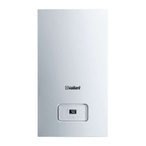
Summary of Contents for Vaillant HOME REGULAR 12-A
- Page 1 Operating instructions For the operator Operating instructions HOME REGULAR GB, IE Publisher/manufacturer Vaillant GmbH Berghauser Str. 40 D-42859 Remscheid Tel. +49 21 91 18‑0 Fax +49 21 91 18‑28 10 info@vaillant.de www.vaillant.de...
-
Page 2: Table Of Contents
Contents Contents Decommissioning...... 10 Temporarily decommissioning Safety ..........3 the product........10 Action-related warnings ....3 Permanently decommissioning the product........10 Intended use ........3 Recycling and disposal..... 10 General safety information..... 4 Guarantee and customer Notes on the documentation ..6 service ........ -
Page 3: Safety
Safety 1 1 Safety ing installations and for hot wa- ter generation. 1.1 Action-related warnings Intended use includes the fol- Classification of action-re- lowing: lated warnings – observance of the operating The action-related warnings instructions included for the are classified in accordance product and any other system with the severity of the pos- components... -
Page 4: General Safety Information
1 Safety 1.3 General safety flue gas may escape into the information room air. ▶ In order to operate the 1.3.1 Installation by skilled product, ensure that the con- tradesmen only densate siphon is always full. The installation, inspection, maintenance and repair of the 1.3.5 Risk of death due to product, as well as the gas ratio explosive and flammable... - Page 5 Safety 1 – The product itself lead to corrosion on the product – to the gas, air, water and and in the air/flue pipe. electricity supplies ▶ Ensure that the supply of – to the entire flue gas install- combustion air is always free ation of fluorine, chlorine, sulphur, –...
-
Page 6: Notes On The Documentation
2 Notes on the documentation 2 Notes on the 3.2 Information on the identification plate documentation The identification plate is mounted on the 2.1 Observing other applicable underside of the product in the factory. documents The identification plate keeps record of ▶... -
Page 7: Design Of The Product
Product description 3 3.4 Overview of the operator Information Meaning control elements on the identi- fication plate Nominal heat output range in heating mode Nominal heat output range in heating mode (condensing technology) Nominal heat output range in hot water handling mode Display button Nominal heating load range... -
Page 8: Operating Levels
4 Operation 4 Operation Symbol Meaning Fault in the product 4.1 Starting up the product – Appears instead of the 4.1.1 Opening the isolator devices basic display. – Appears when switching 1. Ask the competent person who in- stalled the product to explain to you the product to standby mode. -
Page 9: Setting The Hot Water Temperature
Operation 4 ▶ Press repeatedly until the display Conditions: Temperature controlled by the control- shows the required operating mode. ler, with heating mode activated ▶ Symbol Operating mode Set the maximum heating flow temper- Heating + hot water ature on the boiler (→ Page 9). ▶... -
Page 10: Troubleshooting
5 Troubleshooting ◁ ▶ The main power supply is not inter- Clean the casing with a damp cloth and rupted. The product continues to be a little solvent-free soap. supplied with power. 6.3 Checking the condensate drain pipework and tundish 5 Troubleshooting The condensate drain pipework and tun- dish must always be penetrable. -
Page 11: Guarantee And Customer Service
Vaillant scheme. – Immediate help If your Vaillant boiler develops a fault your first action should be to contact your in- staller, as his professional assessment is needed under the terms of our Guarantee. -
Page 12: Appendix
Appendix Appendix A Adjustable values – overview Adjustable values Values Unit Increment, select Default set- ting Min. Max. Heating mode ℃ Heating flow temperature Current value Preset in the system DHW mode ℃ Hot water temperature Current value B Troubleshooting Fault Cause Measure... - Page 16 Nottingham Road Belper Derbyshire DE56 1JT Telephone 0330 100 3461 Telephone (renewables) 0207 022 0928 Vaillant Service Solutions 0330 100 3461 Spares Technical Enquiries 01773 596615 info@vaillant.co.uk technicalspares@groupservice.co.uk www.vaillant.co.uk © These instructions, or parts thereof, are protected by copyright and may be reproduced or distributed only with the manufacturer's written consent.


Need help?
Do you have a question about the HOME REGULAR 12-A and is the answer not in the manual?
Questions and answers