
Subscribe to Our Youtube Channel
Summary of Contents for Kollmorgen Seidel 04S Series
- Page 1 Transistor Controller Series 04S Assembly / Installation / Commissioning Edition 12/99...
- Page 2 Previous editions Edition Comment 09 / 91 First english edition 01 / 93 New layout, completely created with DTP 02 / 98 Seidel Servo Drives, CE, DIN A5 12 / 99 KMS, Layout Technical changes to improve the performance of the equipment may be made without prior notice ! Printed in the Federal Republic of Germany 12/99 Mat.No.
-
Page 3: Table Of Contents
Kollmorgen Series 04S 12.99 Contents Contents Drawing Page Contents ..........A Safety Instructions . -
Page 4: Contents
Series 04S Kollmorgen 12.99 Contents Drawing Page Functions and Options III.1 Important notes ............. . . III-1 III.2 Description of the functions . -
Page 5: Safety Instructions
Kollmorgen Series 04S 12.99 Safety Instructions Safety Instructions Warning symbols : You must observe the important notes in the text, which are marked by the following symbols : danger from electricity general warning and its effects general notes Only properly qualified persons are permitted to carry out activities such as transport, installation, commissioning and maintenance. -
Page 6: Standards And Directives
01 January 1996 EC EMC Directive 89/336/EEC The 04S series of transistor controllers have been tested in an authorised testing laboratory, in a specified configuration with the system components as shown in Chapter II. Any divergence from the configuration and installation which are described in the documentation means that you will yourself be responsible for carrying out new measurements to ensure that the regulatory requirements are fulfilled. -
Page 7: General
Kollmorgen Series 04S 12.99 General Introduction This manual explains the installation, commissioning, adjustment and adaptation of the 04S transistor controller. The manual is divided into 6 chapters : Chapter 1: General Information Chapter 2: Notes on Installation and Commissioning Chapter 3: Functions and Options Chapter 4: Peripheral equipment Chapter 5: Drawings Chapter 6: Appendix and Ordering Information... -
Page 8: Abbreviations Used In This Manual
Series 04S .4.028.6/10 Kollmorgen 12.99 - A Abbreviations used in this manual Abbrev. Meaning Abbrev. Meaning AGND analog ground PELV protected low voltage system ready for operation PSTOP limit-switch input for clockwise rotation European Community pulse-width modulation DGND digital ground tacho generator Deutsches Institut für Normung ballast resistor... -
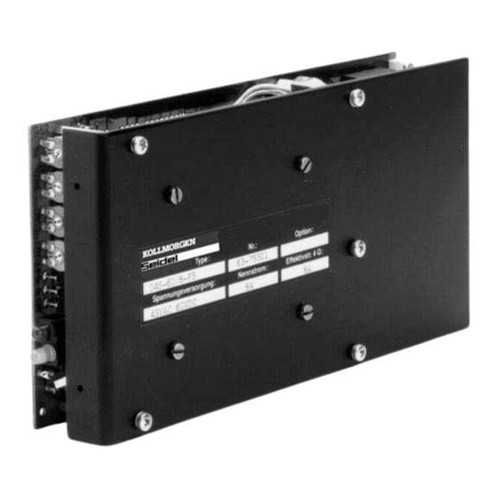
Page 9: Equipment Description
Kollmorgen Series 04S 12.99 04S equipment description Design The following transistor controllers must be operated with forced convection: — all 04S transistor controllers with rated output currents > 8A — all 04S transistor controllers at ambient temperatures > 45°C Plug-in 19”-rack module, connection through module back-panels or mating connector FH24+7 Size Unit Format... -
Page 10: 04S Functional Units
Series 04S Kollmorgen 12.99 I.5.1 04S functional units The following circuit sections are built onto a single Eurocard, 199x100x12TE with SMD-technology: 3-phase power supply with smoothing capacitors (-P-) single phase supply (any phase with the rated voltage, possibly with extra smoothing capacitance) is possible fuses for DC-link, ballast circuit and auxiliary power supply ballast circuit with -w- characteristic... -
Page 11: 04S Technical Data
Kollmorgen Series 04S 12.99 Technical data I.6.1 04S technical data Rated data units 04S-M60/8-PB 04S-M60/12-PB Rated supply voltage 3x43 3x43 Rated installed load 0.75 Rate DC-link voltage Minimum DC-link voltage Rated output current Peak output current Switch-on threshold of ballast circuit Switch-off threshold of ballast circuit Pulse power of ballast circuit 1000... -
Page 12: Permissible Ambient Conditions, Ventilation, Mounting Position
Series 04S Kollmorgen 12.99 I.6.2 Permissible ambient conditions, ventilation, mounting position Transport temperature/humidity see Chapter VI.1 Storage temperature/ see Chapter VI.1 humidity/duration Supply voltage tolerances power stage 3x43V AC ±10% aux. supply (Option -24V-) min. 20V DC / max. 30V DC referred to -GND Ambient temperature T 0 ... -
Page 13: Interference Suppression
Kollmorgen Series 04S 12.99 Interference suppression If interference occurs in the CNC, or the analog or digital path measurement systems, then there are some additional measures, listed below: additional ferrite rings on the motor leads wiring in armature chokes (please use the types supplied by us) HF filter on the CNC setpoint output (RC combination 1kW/10nF) In each case you will have to try out which measures bring sufficient reduction in interference. - Page 14 Series 04S Kollmorgen 12.99 This page has been deliberately left blank Page I - 8 General Chapter I...
-
Page 15: Installation And Commissioning
Kollmorgen Series 04S 12.99 Installation and Commissioning II.1 Important instructions Inspect the nameplate of the controller. Check that the rated voltage and rated current match the transformer and motor data. Do not switch on the operating voltage before you have read Chapter II of this manual (Commissioning). - Page 16 Series 04S Kollmorgen 12.99 II.2 Installation Only professional staff who are qualified in electrical engineering are allowed to install the transistor controller. The installation procedure is described as an example. A different procedure may be sensible or necessary, depending on the application of the equipment. We provide further know-how through training courses (on request).
- Page 17 Kollmorgen Series 04S 12.99 The following notes should make it easier for you to carry out the installation in a sensible sequence, without overlooking anything. 19" rack module in a closed switchgear cabinet. Site Follow Chapter I.6.2 . The site must be free from conductive or aggressive materials. Check that the transistor controller is properly ventilated and Ventilation keep to the permissible ambient temperature, Chapter I.6.2.
-
Page 18: Ii.2.1 - Conform Connections 04S, Overview
Series 04S Kollmorgen 12.99 - E.3.924.1/4 II.2.1 - conform connections 04S, overview - E.3.924.1/4 Page II - 4 Installation and Commissioning Chapter II... -
Page 19: Ii.2.2 Connection Diagram 04S
Kollmorgen Series 04S 12.99 - E.3.924.1/1 II.2.2 Connection diagram 04S - E.3.924.1/1 Chapter II Installation and Commissioning Page II - 5... -
Page 20: Ii.2.3 Module Back-Panels F03Smb And R03Smb
Series 04S Kollmorgen 12.99 II.2.3 Module back-panels F03SMB and R03SMB Type: F03SMB for 04S controllers, connections at the back R03SMB for 04S controllers, connections at the front The module back-panels are attached from behind in the 19” module. The transistor controller is inserted into the module and plugged in to the back-panel. -
Page 21: Pin Assignments For 04S / R03S-Mb
Kollmorgen Series 04S 12.99 II.2.3.2 Pin assignments for 04S / R03S-MB Edge conn. 20/2x10 pin Short M7/24 Combicon conn. Signal name (pin no.) (terminal no.) designation (solder print) Setpoint 1+ SW 1 + Pos.Stop PSTOP Setpoint 1- SW 1 - Setpoint 2+ SW 2 + Neg.Stop... -
Page 22: Ii.3 Commissioning
Series 04S Kollmorgen 12.99 II.3 Commissioning II.3.1 Important instructions Check that the instructions in Chapter II.1 have been followed. The correct step-by-step procedure for commissioning will help you to avoid causing any damage. If you require further information, please get in touch with our applications department. -
Page 23: Ii.3.2 Notes On Commissioning
Kollmorgen Series 04S 12.99 II.3.2 Notes on commissioning The procedure for commissioning is only described very briefly here. We can provide you with further know-how in one of our training courses (on request). In multi-axis systems, commission each transistor controller individually. Caution ! Check that all current-carrying connections are protected against accidental contact. - Page 24 Series 04S Kollmorgen 12.99 The following instructions should help you to carry out the commissioning in a sensible sequence, without causing any hazard to persons or machinery. Check that the wiring carried out matches the wiring diagram Check installation (transformer, motor, and earth connections, control signals). Check the instrument nameplates (rated voltage and current, special adjustment - if required).
-
Page 25: Functions And Options
Kollmorgen Series 04S 12.99 Functions and Options III.1 Important notes Alterations to the transistor controller can only be carried out by professionally qualified personnel. Setting and optimisation of the transistor controller, and the configuration of circuit blocks by using the solder links is permitted. Any further manipulation will invalidate the guarantee. -
Page 26: Iii.2.1.3 Digital Control Inputs
Series 04S Kollmorgen 12.99 III.2.1.3 Digital control inputs All the inputs are electrically isolated by optocouplers. The ground reference is Digital-GND (DGND, pin 10z). The logic is designed for +24V/8mA (PLC-compatible) with a logic-high level of +12 — 30V. Switching with +15V (terminal 13) is possible if required. In this case, Digital-GND (Pin 10z) and Analog-GND (pins 10db, terminal 12) must be joined. -
Page 27: Iii.2.2 Output Functions
Kollmorgen Series 04S 12.99 III.2.2 Output functions III.2.2.1 Armature current monitor output The output (IDC, pin 16b or terminal 7) delivers ±10 V against AGND for ± peak instrument current. The measured value is nearly proportional to the motor torque which is delivered. The output resistance is 2.2kW This signal can also be used as a current setpoint signal for a second, 1:1 connected (slave) transistor controller in a tandem drive. -
Page 28: Iii.2.3 Adjustment Facilities
Series 04S Kollmorgen 12.99 III.2.3 Adjustment facilities III.2.3.1 Tachometer potentiometer P1 The potentiometer P1 is used for the fine adjustment of the tachometer. The range of adjustment is 8 — 75 V. The standard components installed are for tacho voltages of 8V or 75V at a setpoint voltage of 10V and with the potentiometer on the right stop or left stop respectively. -
Page 29: Iii.2.4 Other Functions
Kollmorgen Series 04S 12.99 III.2.4 Other functions III.2.4.1 Effective (r.m.s.) current I The controller is capable of delivering the peak instrument current I for a maximum of 5s, PEAK after which it is limited to the preset rated current I . -
Page 30: T - Monitoring
Series 04S Kollmorgen 12.99 III.2.4.4 t - monitoring When the preset effective (r.m.s.) current limit is reached, the pulse current is limited until the effective loading falls. This does not affect the BTB (system ready) signalling. III.2.4.5 Indicators Red and green LEDs for system-ready (BTB) and combined fault [FAULT] The green LED lights up when the DC-link voltage is present and the auxiliary voltage supply (±15V) is functioning properly. -
Page 31: Iii.3
Kollmorgen Series 04S 12.99 III.3 Options III.3.1 1:1 - control You can change the speed controller over to current control by closing the solder link LB 1:1. The proportional section of the amplification is set to 1 in this case, the integral section is bridged and the tacho signal is switched off internally. -
Page 32: Iii.3.4 Layout Of The Solder Links
Series 04S Kollmorgen 12.99 - E.4.924.1/2 III.3.4 Layout of the solder links - E.4.924.1/2 Page III - 8 Functions and Options Chapter III... -
Page 33: Peripheral Components
Kollmorgen Series 04S 12.99 Peripheral components IV.1 Isolating transformers Isolating transformers are required to operate the equipment. In order to ensure that the installation functions properly and the guarantee conditions are fulfilled, the isolating transformers must meet the following specification: Type: 3-phase isolating transformers, with a screen winding to VDE 0550, in Y/y or Y/D configuration. -
Page 34: Iv.1.1 Transformer Dimensions And Connections
Series 04S Kollmorgen 12.99 - E.4.924.4/2 IV.1.1 Transformer dimensions and connections - E.4.924.4/2 Page IV - 2 Peripheral components Chapter IV... -
Page 35: Iv.2 Chokes
Kollmorgen Series 04S 12.99 - E.4.924.4/1 IV.2 Chokes IV.2.1 Choke dimensions and connections - E.4.924.4/1 Chapter IV Peripheral components Page IV - 3... - Page 36 Series 04S Kollmorgen 12.99 This page has been deliberately left blank Page IV - 4 Peripheral components Chapter IV...
-
Page 37: Drawings
Kollmorgen Series 04S 12.99 - E.4.924.4/5 Drawings Front panel 04S (12TE), optional (TE = width units) - E.4.924.4/5 04S-M60/8 Chapter V Drawings Page V - 1... -
Page 38: Component Layout 04S
Series 04S Kollmorgen 12.99 - E.4.924.2/1 Component layout 04S - E.4.924.2/1 Page V - 2 Drawings Chapter V... -
Page 39: Back-Panels F03Smb / R03Smb
Kollmorgen Series 04S 12.99 - E.4.911.4/8 Back-panels F03SMB / R03SMB F 03 SMB R 03 SMB - E.4.911.4/8 Chapter V Drawings Page V - 3... - Page 40 Series 04S Kollmorgen 12.99 This page has been deliberately left blank Page V - 4 Drawings Chapter V...
-
Page 41: Appendix
Kollmorgen Series 04S 12.99 Appendix VI.1 Delivery package, transport, storage, maintenance, disposal Delivery — 1 series 04S transistor controller package : — installation/commissioning manual for 04S — accessories as ordered (back-panels, 19" components) Transport : — only be qualified personnel —... - Page 42 Series 04S Kollmorgen 12.99 VI.2 Fault-finding The table below should be regarded as a “First-aid” box. There may be a wide variety of possible reasons for a fault, depending on the conditions in your system. Multi-axis systems may conceal further causes of a fault. Our applications department can give you further assistance with problems.
-
Page 43: Vi.3 Glossary
Kollmorgen Series 04S 12.99 VI.3 Glossary AC-gain, P-gain proportion gain of a control loop ballast circuit converts superfluous energy, which is regenerated by the motor during braking, into heat in the ballast resistor. common-mode voltage amplitude of the common-mode disturbance which can be eliminated by a differential input continuous ballast power the average power which can be dissipated by the ballast circuit... -
Page 44: Vi.4 Index
Series 04S Kollmorgen 12.99 VI.4 Index A abbreviations ... I-2 monitoring functions ..I-4 AGND ....I-2 mounting position . - Page 45 Kollmorgen Series 04S 12.99 This page has been deliberately left blank Chapter VI Appendix Page VI - 5...
- Page 46 Ge rm a n y / A ll ema g n e DIGIMATIC M.C.A. s.r.l. Ormhöjgaardvej 12-14 Via f. Turati 21 Kollmorgen Seidel GmbH & Co. KG Verkaufsniederlassung Nord 8700 Horsens 20016 Pero (Mi) Tel.: +45 - 76 26 12 00 Tel.: +39(0)02 - 33 91 04 50...
Need help?
Do you have a question about the 04S Series and is the answer not in the manual?
Questions and answers