Table of Contents
Advertisement
Advertisement
Table of Contents

Summary of Contents for Vesper Cortex M1
- Page 1 M1 INSTALLATION GUIDE M1 HUB - USA & CANADA M1 HUB - REST OF WORLD...
-
Page 2: Table Of Contents
Index Introduction To confirm AIS operation Items you need for installation Monitoring and control Cortex Monitor App introduction The Cortex network LED indicator panel To program GPIO sensors with the Cortex Onboard App M1 port locations To program GPIO sensors with a handset M1 positioning Heading Sensor M1 mounting... -
Page 3: Introduction
Introduction The Vesper Marine Cortex M1 hub is an AIS Class-B SO-TDMA The M1 hub also features an integrated GNSS receiver transponder with integrated on board and remote vessel (supporting GPS, GLONASS, BeiDou, Galilleo), fully isolated monitoring and control. NMEA ports and a high-power external speaker driver. Internal... -
Page 4: Items You Need For Installation
Items you need for installation and configuring Required components (included) M1 hub GPS antenna (included) M1 hub GPS Antenna Power cable WiFi antenna Audio cable Input / Output cable Required components (not included) AIS/VHF antenna External WiFi External cellular antenna antenna (optional) Fuse or circuit breaker... - Page 5 Onboard App Introduction Cortex Onboard is a free Android and Apple iOS app that connects your phone or tablet Cortex Onboard App Main Menu options to the WiFi of the M1. Use the Cortex Onboard App to configure, Select the Main Menu icon ( manage and display M1 data.
-
Page 6: The Cortex Network
The Cortex network Cellular GPS (10 Hz) Antenna Antenna AIS / VHF (included) Antenna Power WiFi Antenna Secondary VHF (included) 12/24V Cortex Handsets WiFi data External Speaker NMEA 2000 NMEA 0183 Wind Chart plotter Remote monitoring Input and Output examples Heading Depth Others... -
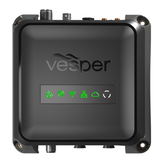
Page 7: Led Indicator Panel
LED indicator panel M1 port locations The M1 indicator panel provides system status via orange, green 1 WiFi Antenna port 4 DC Power Supply and red illumination in various stages of solid or flashing. (12V or 24V DC) 2 GPS Antenna port 5 Auxiliary VHF port 3 Cellular Antenna port eg. -
Page 8: M1 Positioning
M1 positioning M1 mounting Allow at least 2"/ 50mm at each connector 1. Use the M1 as a template for mounting holes. row to give sufficient room for cable clearance and connection. 2. Mark the holes on the mounting surface and drill them Allow at least 8"... -
Page 9: To Connect Power
To connect power M1 DC power requirements: HINT - Connect the M1 to a power supply that will remain on even when the vessel’s batteries may be turned off. (eg, connected to the 24hr circuit) Nominal 0.5A @ 12V This is important for monitoring to ensure the M1 remains on even VHF High Power Transmit (Max) 6.0A @ 12V when the main DC power of the vessel is switched off. -
Page 10: Ais / Vhf Antenna (Required)
AIS / VHF Antenna (required) Internal AIS / VHF splitter The M1 shares one antenna for both AIS and VHF functions. The M1 incorporates an AIS/VHF splitter to share one AIS/VHF A dedicated VHF antenna is required. antenna and to allow connection to an external VHF radio via the auxiliary port. -
Page 11: External Gps Antenna (Required)
GPS antenna. CAUTION - The Vesper Marine GPS antenna is specifically designed for use with Vesper Marine devices. Use of a different GPS antenna may damage the M1 hub and void the warranty. > After installing the GPS Antenna,... -
Page 12: External Wifi Antenna (Recommended)
External WiFi Antenna (recommended) External WiFi Antenna installation Consider these WiFi requirements when choosing a position: Allow enough clearance space when installing the M1 for the WiFi Antenna External WiFi Antenna to be positioned in a vertical position to increase WiFi range. Do not place the External WiFi Antenna near or in the path of radar, HF and/or high power satellite communication (such as Iridium Go) antennas. - Page 13 NMEA 2000 Gateway The M1 incorporates an NMEA Gateway to allow different brands NMEA 2000 Gateway example and generations of electronics on NMEA 0183 or 2000 networks to talk to each other automatically and transfer data without extra multiplexing devices or configuring. WiFi data The Gateway translates selected NMEA 2000 sensor data for compatibility with mobile apps.
-
Page 14: To Connect To Nmea 2000
To connect to NMEA 2000 NMEA 2000 network connection example The M1 can be connected to an NMEA 2000 network to enable AIS and Navigation data, including GPS to be sent to other NMEA 2000 devices. - The NMEA sentences (PGNs) supported are listed on page 26. - A NMEA 2000 drop cable and T connector are required to connect the M1 to a vessel’s NMEA 2000 network. -
Page 15: To Connect To Nmea 0183
To connect to NMEA 0183 NMEA 0183 network connection diagram NMEA 0183 devices can receive AIS data when connected to the M1 I/O (Sensors GPIO / NMEA 0183) expansion port. - The NMEA sentences supported are included on page 26. The NMEA Baud rate can be changed via the Cortex Onboard App or from the H1 handset. -
Page 16: External Cellular Antenna (Optional)
External Cellular Antenna (optional) External Cellular Antenna mounting The Vesper Marine External Cellular Antenna may be connected Deck mount Deck mount for enhanced cellular coverage. Consider the following location on base flush and connection requirements: The external cellular antenna is rated IP67 and UV stable for external installation. -
Page 17: External Speaker (Optional)
DARK GREEN Reserved An optional external speaker can be connected to the M1 for The Vesper Marine External Speaker (Part Number 111210) is audio alarms or voice alarms using the Audio cable. purpose designed for the marine environment. NMEA RX (-) B... -
Page 18: Connecting Devices To An M1
To connect a mobile device Once installation of the M1, cables and antennas are complete, 1 Turn Cortex M1 and device ON the M1 is configured using the Cortex On board App on a mobile Switch the vessel's batteries ON to power the M1. -
Page 19: To Connect A Handset
To connect a handset Device connection FAQs 1 Turn M1 ON If the device (handset or mobile device) displays 'Trying to Switch the vessel's batteries ON to power the M1. connect...’ for a long period, it has not made a WiFi connection to the M1. -
Page 20: Mmsi Programming Introduction
> Name (Enter the vessel’s name) Programming must be carried out by a Vesper Marine dealer. > Callsign (Enter the vessel’s callsign) The included instructions contain information on how to verify the >... -
Page 21: To Program An Mmsi With A Handset
To program an MMSI with a handset To confirm AIS operation 1 Turn Cortex M1 and handset ON LED indicator panel Switch the vessel's batteries ON to power the M1 2 Connect the handset to the M1 via WiFi Green light indicates... -
Page 22: Monitoring And Control
Vessel heading (refer Heading Sensor Calibration pg24) scan the QR code to activate monitoring for your Cortex M1. Once activated it can take a few minutes for your Cortex M1 to connect Barometric pressure for the first time. You can now view the status of M1 sensors on the Monitor app. -
Page 23: To Program Gpio Sensors With The Cortex Onboard App
2 x input/output, 3 x input. 3 x input, 2 x input/output. 1 Download the Cortex Onboard App 1 Turn Cortex M1 and handset ON Free download from the iOS or Google Play stores Switch the vessels batteries ON to power the M1... -
Page 24: Heading Sensor
The Onboard App will ask if you would like to perform the firmware update. Select Yes to update. The Cortex Onboard App 1 Turn Cortex M1 and device ON Note - If you have registered your Cortex, emails will advise when Switch the vessel's batteries ON to power the M1 a firmware update is available. -
Page 25: M1 Wiring Color Codes
M1 Wiring color codes POWER +VE BLACK POWER -VE NMEA TX (+) A ORANGE ORANGE AUDIO +VE NMEA TX (-) B WHITE BLACK AUDIO -VE NMEA RX (+) A DARK GREEN Reserved - Do not connect NMEA RX (-) B YELLOW BROWN Reserved - Do not connect... -
Page 26: Nmea Pgns And Monitoring Instruments
NMEA PGNs and Monitoring Instruments Received PGNs are translated and outputted over NMEA 0183 Received PGNs Monitoring Instruments and WiFi. See www.vespermarine.com for an up to date list. Description 0183 Translation Description 127250 Vessel Heading Vessel Heading 128259 Speed, water referenced Speed, water referenced 128267 Water depth... -
Page 27: Gpio Sensor Wiring - Lighting Remote Control
GPIO sensor wiring - Lighting remote control GPIO sensor configuration example Note - Lighting on/off remote control is one example of what an Sensor / control name Anchor light output relay may switch and control. Sensor / control type On/Off switch +ve 12/24V Light Output relay... -
Page 28: Gpio Sensor Wiring - Motion Sensor
BLACK GPIO GND GPIO sensor wiring - Motion sensor GPIO sensor configuration example Sensor / control name Cockpit Motion 1 Sensor / control type Security sensor Default input high Pullup enabled Active when high Yes, normally closed +ve 12/24V PULLUP VOLTAGE LIGHT INPUT/OUTPUT 2... -
Page 29: Gpio Sensor Wiring - High Water Sensor
GPIO sensor wiring - High water sensor add pullup to system voltage GPIO sensor configuration example Sensor / control name Bilge high water Sensor / control type High water sensor Default input high Pullup enabled +ve 12/24V Active when high No, normally open PULLUP VOLTAGE... -
Page 30: Gpio Sensor Wiring - Bilge Pump Activation Sensor
GPIO sensor wiring - Bilge pump activation sensor BILGE PUMP GPIO sensor configuration example Sensor / control name Engine room bilge Sensor / control type Bilge pump Default input high Pullup disabled +ve 12/24V Active when high Yes, normally closed Three way switch manual on / off / auto on Float switch... -
Page 31: Gpio Sensor Wiring - Hatch / Door Open Sensor
add system voltage and GPIO sensor wiring - Hatch / door open sensor connect pullp GPIO sensor configuration example Sensor / control name Forward Hatch 1 Sensor / control type Security sensor Default input high Pullup enabled Active when high No, normally open +ve 12/24V PULLUP... -
Page 32: Gpio Sensor Wiring - Smoke / Heat Sensor
GPIO sensor wiring - Smoke / Heat sensor SMOKE / HEAT DETECTOR GPIO sensor configuration example Sensor / control name Engine room smoke Sensor / control type Smoke sensor Default input high Pullup enabled Active when high No, normally open +ve 12/24V PULLUP VOLTAGE... -
Page 33: Specifications
Specifications M1 GENERAL VHF VOICE M1 NETWORKING VHF FREQUENCY 1 x Isolated Micro-C male 168 x 168 x 58.7mm HUB SIZE RANGE port, AIS, GPS & MOB PGN (6 5/8” x 6 5/8” x 2 5/16” ) NMEA 2000 GATEWAY 156.025–161.600 MHz output, Gateway Translations 9-33V. - Page 34 Dimensions M1 SENSORS H1 / H1P Handset HEADING Internal use only Update rate 1Hz max BAROMETER (averaged) BATTERY VOLTAGE Measured at power input EXTERNAL SENSORS 5 Inputs, Digital (0-24V) INPUTS H1 AND H1P HANDSET SPECIFICATIONS 164.8 x 71.8 x 21.4mm HANDSET SIZE (6 1/2”...
- Page 35 0.5:1 Scale 15mm (5/8”) 21.5mm (7/8”) 7mm (1/4”) Dimensions 0.5:1 Scale 21.5mm (7/8”) 0.5:1 Scale External GPS Antenna External Cellular Antenna Ø22mm (7/8”) Ø60mm (2 3/8”) 0.5:1 Scale 4mm (5/32”) Ø60mm (2 3/8”) Ø42mm (1 5/8”) Side Side 18.5mm (3/4”) Ø22mm (7/8”) 90mm (3 37/64”) 15mm (5/8”)
-
Page 36: Led Icon Troubleshooting
Orange Flashing AUX VHF is transmitting. Green Solid Normal AIS + VHF Operation. Solid A VHF/DSC/AIS System Check has failed. Contact Vesper Marine technical support. Flashing Antenna short circuit or open circuit detected - may also indicate a high VSWR. - Page 37 Solid Attempting to connect or connected to a cellular network. Cloud Orange Flashing Flashes when attempting to connect to the Vesper Cloud. Cloud Green Solid Connected to the Vesper Cloud. Note - on the Lite plan it will only connect every 12 hours for 10 minutes.
-
Page 38: Warnings
AIS Transponder you fully accept this risk and agree maintenue entre l’antenne de ce dispositif et les personnes pendant son to hold Vesper Marine Limited harmless. If you do not agree to accept all risk, fonctionnement. Pour assurer la sécurité, les opérations plus près de cette return this product unused in its original factory condition to your dealer for a distance ne sont pas recommandées. -
Page 39: Warranty
AIS transmitter. Please contact the relevant authority in your country for more product. information. Vesper Marine retains the exclusive right to repair or replace the unit at its sole discretion. In the event Vesper Marine chooses to replace the unit it may be For Customers in the USA replaced with a factory reconditioned unit or a new unit at its sole discretion. - Page 40 Vesper Marine declares that this product is in compliance with Copyright © 2020, Vesper Marine Ltd. Directive 2014/53/EU. Vesper Marine, Vesper, Cortex, VHF Reimagined, WatchMate, AIS The full text of the EU Declaration of Conformity is available WatchMate, WatchMate Vision, deckWatch, smartAIS and Always at the following internet address: www.vespermarine.com/...
Need help?
Do you have a question about the Cortex M1 and is the answer not in the manual?
Questions and answers