Table of Contents

Summary of Contents for J&R MANUFACTURING 700E
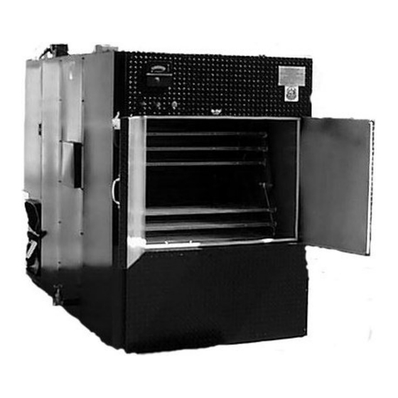
- Page 1 OYLER BARBECUE PIT MODEL 700E/ 1300E OPERATIONS AND SERVICE MANUAL J&R M ANUFACTURING, (972) 285-4855 (Texas) 820 W. Kearney (800) 527-4831 (50 states & Canada) Suite B (972) 289-0801 (Parts and Service) Mesquite, Texas 75149 (972) 288-9488 (Fax)
- Page 2 SN _______________...
- Page 3 WARNINGS! Disposal of Ashes Ashes should be placed in a metal container with a tight-fitting lid. The closed container of ashes should be placed on a noncombustible floor or on the ground, well away from all combustible materials, pending final disposal. If the ashes are disposed of by burial in soil or otherwise locally dispersed, they should be retained in the closed container until all cinders have thoroughly cooled.
- Page 5 OYLER BARBECUE PIT 700E 1300E ODELS OPERATIONS AND SERVICE MANUAL MANUFACTURED BY: J & R MANUFACTURING, INC. Rev. 1- 13...
-
Page 7: Table Of Contents
CONTENTS YLER ARBECUE 700E / 1300E ODEL NSTALLATION NSTRUCTIONS PERATING NSTRUCTIONS AINTENANCE AND LEANING ROUBLESHOOTING 1 – S IGURE UGGESTED NSTALLATION 2 – M 700E D IGURE ODEL ETAIL HEET 3 – T IGURE HROUGH THE NSTALLATION 4 – M... -
Page 9: Oyler Barbecue Pit Model 700E / 1300E
YLER ARBECUE 700E / 1300E ODEL COOK MODES The “E” version of the Oyler Barbecue Pit Model 700/1300 uses electric heating elements in addition to wood fuel for the cooking heat source. Additional controls allow the operator to cook in one of two “Cook” Modes, “Standard” or “Dual Fuel”. - Page 10 COOK AND HOLD MODE The difference between this mode and “Cook” mode (“Standard or “Dual Fuel”) is the temperature control is shifted away from the primary thermostat to a fixed secondary (or Hold) thermostat after the operator set timer, located on the instrument panel, counts down.
-
Page 11: Installation Instructions
HANDLING A Model 700E can be handled with a forklift if the lift has a 6,000 pound capacity. A Model 1300E will require an 8,000 pound lift. The extra capacity lifts are necessary due to the size of the units. Whenever possible, the unit should be trucked from the rear. - Page 12 AIR BALANCE The building air balance is very important to the proper operation of your Oyler Pit. The Oyler design is based on the induction of air into the pit due to the “stack effect” of the chimney. The “stack effect” is the term used to describe the upward airflow created in a chimney based on the chimney height and the temperature difference between the bottom (inlet) and top (discharge).
- Page 13 EXTERIOR INSTALLATION There are two types of exterior installations. The unit can be placed entirely outside or you may wish to have only the front part of the unit inside your building. In either case, the unit should be painted and the top seams sealed for exterior installation.
- Page 14 SMOKESTACK A smokestack is required for proper operation of the pit. It should be at least 10 feet in height (from the pit to the top of the stack) and 18 inches in diameter. Please check your local mechanical and fire codes prior to installing the smokestack TO ENSURE THAT THE PROPER STACK IS CHOSEN AND THAT IT IS CORRECTLY INSTALLED.
- Page 15 MODEL 700 - WIRE RACKS WIRE RACKS AND HANGERS ARE SHIPPED UNASSEMBLED SO THEY MAY BE USED WHERE REQUIRED IN THE UNIT. HOWEVER, THEY MUST BE PROPERLY ASSEMBLED BEFORE USE TO REDUCE THE POSSIBILITY OF A RACK JAM. PLEASE FOLLOW INSTRUCTIONS BELOW. LOWER RACKS MUST HAVE THE FOUR (4) "NIBS"...
-
Page 16: Operating Instructions
OPERATING INSTRUCTIONS MODEL 700E AND MODEL 1300E START-UP After the pit is installed, leveled, stacked, and connected to the electrical supply, check for proper operation: Turn the thermostat set point above and then below the actual temperature. The combustion air damper on the firebox should open and close. - Page 17 MEAT LOADING The first time the pit is fired, it is recommended that you allow it to operate for several hours while empty. This allows any residues (oil, paper, etc.) to be removed. After this is done, you may load meat onto the racks. Take care when loading to keep the load balanced.
- Page 18 SUGGESTED COOKING TIMES AND TEMPERATURES EMPERATURE OOKING Beef Brisket 200° F. 14 Hours 12 – 14 Lbs.) Pork Shoulder 200° F. 14 Hours (12 – 14 Lbs.) Pork Ribs 250° F. 3 Hours (3 and down) Sausage 225° F. 1 Hour Hams (pre-cooked) 225°...
-
Page 19: Maintenance And Cleaning
MAINTENANCE AND CLEANING MODEL 700E AND MODEL 1300E PIT DESIGN Smoke and heat from the firebox enter the cooking compartment through refractory-lined flues. Smoke exits this area through a separate flue. Temperature control is effected by regulating the flow of combustion air into the firebox and the discharge from the cooking compartment. - Page 20 Leave the racks in place and fill the pit with a hot water/oven cleaner solution up to the middle of the exit flue opening. Heat the pit up to 250° and allow the racks to revolve. Continue for at least 4 hours, drain and rinse the pit thoroughly.
- Page 21 Check the evacuation (bypass) system for proper operation. Open the front doors and make sure that the bypass dampers operate properly. They should seal tightly when the front doors are closed and latched (and the “Evac” switch, if the pit is equipped with one, is off). Clean excess carbon build-up or residue from the rear area of the pit, including the inside of the access door above the firebox, the firebox door and the area around the firebox door.
- Page 22 BLANK PAGE...
-
Page 23: Troubleshooting
TROUBLESHOOTING Combustion air damper and exit flue fails to open and close. ROBLEM One of the following components is inoperative: AUSES the thermostat, the damper motor, or the linkage between the motor and the dampers. ROCEDURE Open the access door to flues and dampers. (see Figure 1) Make sure that the linkage is attached to the motor and that all pivot pins are in place. - Page 24 ROCEDURE Proceed as in problem 1, if the combustion damper and exit flue are not opening. Verify that the exit flue is clean. If the problem still exists, make sure that the two large bypass dampers are sealing against their respective gasketed seats.
- Page 25 Rotisserie does not revolve. ROBLEM One or more of the following: AUSES motor failure, circuit failure, gearbox failure, broken chain, loose sprocket, or the overload device has tripped. ROCEDURE Inspect the cooking compartment to be sure that the rotisserie assembly has not jammed. If the assembly is okay and the load is evenly balanced, turn the rotisserie switch to the “off”...
- Page 26 If the motor does not run, shut the electrical supply to the pit off and remove the gearbox and motor assembly as indicated above. Separate the two, energize the pit circuit, and turn the rotisserie switch on. If the motor runs, replace the gearbox.
- Page 27 ROCEDURE Shut the pit circuit off and tag it. Open the motor/gearbox access door. Inspect the chain. It should not have excessive slack over or under the gearbox sprocket. If it does, remove any meat that might be on the racks and loosen the four bolts securing the gearbox to its base.
- Page 28 BLANK PAGE...
- Page 29 FIGURE 1 LEGEND 1. RAIN CAP 8. FURDOWN (SUGGESTION ONLY) 2. COUNTER FLASHING 9. FIREBOX DOOR 3. ROOF JACK 10. CONCRETE PAD (RECOMMENDED) 4. SMOKESTACK 4 TO 6 INCHES HIGH OR USE STEEL BASE 5. ACCESS PANEL TO GEARBOX, MOTOR, GREASE FITTINGS 11.
- Page 31 Low Volume Exhaust Fan Eyebrow Hood Figure 3...
- Page 34 BLANK PAGE...
- Page 36 Figure 7...
- Page 38 BLANK PAGE...
- Page 40 BLANK PAGE...
- Page 42 BLANK PAGE...
-
Page 43: Thermostat Manuals
IM800-06 800 Series Indicating Temperature Controls U N I T E D E L E C T R I C Types 800, T800, 802 C O N T R O L S Please refer to IMT120 for Explosion Proof Types Installation and Maintenance 820E and 822E Instructions... - Page 44 WIRING Part II - Adjustments Tools Needed (Refer to Figure 3) DISCONNECT ALL SUPPLY CIRCUITS BEFORE WIRING. ELECTRICAL RATINGS STATED IN LITERATURE AND ON NAMEPLATE SHOULD 5/64” Allen Wrench NEVER BE EXCEEDED. OVERLOAD ON A SWITCH CAN CAUSE FAILURE 5/16” Open End Wrench (2 required) ON THE FIRST CYCLE.
- Page 45 General Layout Adjusting Thermometer Type T800 Use the in-process adjustment to check the control. Differences between the test instrument and the thermometer can be corrected by turning the zero adjustment “C” per Figure 3 on the thermal assembly. Turning in lowers SWITCH 1 indicated reading.
- Page 46 RECoMMENDED PRACTICES AND WARNINGS United Electric Controls Company recommends careful consideration of the following factors when specifying and installing UE pressure and temperature units. Before installing a unit, the Installation and Maintenance instructions provided with unit must be read and understood. •...
- Page 56 BLANK PAGE...
-
Page 57: Warranty
WARRANTY J & R MANUFACTURING, INC. warrants its equipment against defective parts and workmanship under normal use and when installed in accordance with manufacturer’s recommendations for a period of six (6) months on parts and thirty (30) days on labor with the following provisions: 1. - Page 58 BLANK PAGE...
Need help?
Do you have a question about the 700E and is the answer not in the manual?
Questions and answers