
Related Manuals for LUXO Burton AIM-100 Minor Surgery Light

Summary of Contents for LUXO Burton AIM-100 Minor Surgery Light
- Page 1 AIM-100 ™ OPERATION & MAINTENANCE INSTRUCTIONS PERFORMANCE RELIABILITY VALUE The Right Light MINOR SURGERY...
-
Page 2: Table Of Contents
The following models are covered in this manual: 120 V 240 V 100 V AIM-100™ Floor Stand Version A100FL A102 FL A101FL AIM-100™ Single Ceiling Version A100SC A102 SC A101SC AIM-100™ Double Ceiling Version A100DC A102 DC A101DC AIM-100™ Wall Mount Version A100W A102 W A101W... -
Page 3: Introduction
Introduction Congratulations on your purchase of the AIM-100™ Minor Surgery Light! The AIM-100™ Minor Surgery Light is designed to give the professional health care market superior performance, reliability and value. The light contains advanced optical and mechanical solutions aimed at offering you an optimal working environment for efficient and comfortable procedures, while assisting in enhancing performance. -
Page 4: Symbols & Warnings
Symbols & Warnings Symbols Used In This Manual Disregarding this instruction can present the risk of a serious WARNING or fatal injury. Disregarding this instruction can result in medium to light CAUTION injury and damage to property. Provides usage tips and useful information. IMPORTANT Symbols &... -
Page 5: Technical Description
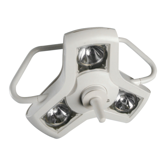
Technical Description Main components Figure 1 Main components Single Ceiling Version Consists of one AIM-100™ light head attached to a suspension system. Figure 2 Single Ceiling Version AIM-100™ Operation and Maintenance Manual – 1008189 A03 5... -
Page 6: Double Ceiling Version
Double Ceiling Version Consists of two AIM-100™ light heads attached to separate arms, but with a common down tube secured to the structural ceiling. Figure 3 Double ceiling version Wall Mount Version Consists of one AIM-100™ light head attached to a suspension system. The suspension system is attached to a wall mount, which is secured to the wall. -
Page 7: Range Of Motion - Ceiling Version
Range of motion – Ceiling version Figure 5 Vertical range of motion. Figure 6 Horizontal range of motion (unlimited rotation in both axes) AIM-100™ Operation and Maintenance Manual – 1008189 A03 7... -
Page 8: Floor Stand Version
Floor Stand Version Consists of one AIM-100™ light head attached to a mobile suspension system. The suspension system consists of the following: • A mobile stand with an upright pole. The stand has castors to facilitate movement. • A spring arm between the upright pole and the light head. •... -
Page 9: Operation
Operation Safety Precautions WARNING During normal operation do not touch any optical surfaces Risk of burn (e.g. bulb, reflector, window). WARNING Do not obstruct any vents or openings. Fire hazard WARNING Do not use the fixture if, for any reason, it does not appear to work properly. -
Page 10: Using Dimmer (Optional)
Using Dimmer (Optional, for 120V version only) Sterilization Protocol – Handle The AIM-100™ handle assembly is made from high-temperature resistant Noryl™ plastic. It should normally withstand up to 2500 sterilization cycles according to the procedure below, without deterioration. If the handle starts cracking or flashing it should be replaced. -
Page 11: Maneuvering The Light Head
Maneuvering the Light Head If a procedure is to be performed which requires a sterile field, the handle must be sterilized or sterile disposable covers for the cover must be used. At no time during the procedure may any other part of the fixture be touched. The AIM-100™ arm system and light head attachment were designed so the light head could be positioned at any location within its range of motion using only the handle. -
Page 12: Using Sterile Disposable Covers For The Handle
Using Sterile Disposable Covers for the Handle The handle is designed to fit sterile disposable covers (Burton part #0008100PK). To attach the cover to the handle, simply slip it on to the handle and make sure it engages with the small flange (indicated on illustration below) on the handle. AIM-100™... -
Page 13: Maintenance
Maintenance WARNING The proposed maintenance schedule is a suggestion. Depending on the use of the product and the operating environment, the required maintenance may not be limited to this. It is the responsibility of the user to service and maintain the product as needed. -
Page 14: Changing Bulbs
Changing Bulbs WARNING Avoid replacing lamps when the fixture is hot. Wait at Risk of burn least 30 minutes for it to cool. WARNING Replace bulbs with same type and rating. Purchase bulbs Fire hazard from a Burton-authorized distributor. (Halogen, 35W (37W) IRC, 12 volt, bi-pin, GY6.35 base. -
Page 15: Replacing Fuses
5. Use gloves or a dry tissue when replacing the bulb. Pull it straight out of the socket. Insert the new bulb in the opposite order. Do not overtighten the screws holding the pods. Replacing Fuses WARNING Replace only with correct fuse rating. Fire hazard For 120 V version: T, 3A, 250V. - Page 16 Ceiling Versions 120 V The fuse holder is located on the wall switch. Disconnect power to the lamp circuit at the main breaker before replacing the fuse. Use a flat screwdriver to open the fuse holder and replace the fuse. Ceiling Versions 100 V and 240 V For the 100 V and 240 V ceiling versions, the fuse holder is located adjacent to the terminal block on the ceiling casting.
-
Page 17: Normal Cleaning
Normal Cleaning WARNING For all cleaning work, power off the equipment and secure Electrical shock it from being switched on again. Make sure that no cleaning fluid runs into the equipment. NOTE Apart from mild detergents and alcohol, no other cleaning Damage to agents or chemicals should be used on the product. -
Page 18: Adjusting Arm Tension
Adjusting Arm Tension If the spring inside the articulating arm is too strong or weak, the light head won’t hang properly when positioned and released by the operator. It will drift up or down, depending on spring setting. To adjust the spring tension: 1. -
Page 19: Technical Data
93/42/EEC Medical Device Directive. Authorized European Luxo ASA Representative: Drammensveien 175, N-0277 Oslo, Norway Tel: +47 22574000, www.luxo.com CE classification Class I Electrical Supply connections 100, 120 or 240 V ac, 50/60 Hz... - Page 20 IEC60320C13, length: 2,5 m. Transport and Storage Conditions Ambient temperature 0 - 70°C (32 - 158°F) Relative humidity 10 - 75% (no condensation) Atmospheric pressure 500 - 1060 hPa Operation Conditions Ambient temperature 10 - 30°C (50 - 86°F) Relative humidity 30 - 75% Atmospheric pressure 700 -1060 hPa...
-
Page 21: Troubleshooting Guide
and manufacturing of our lights we strive to minimize the ecological impact. Materials No hazardous materials are used in the production of the AIM-100™. Plastic The plastic parts are made from an ECO-compliant grade of plastics. This means that no brominated or chlorinated substances are used in the production of the raw-material. -
Page 22: Replacement Parts
Burton will make available to the purchaser, or his representative, technical material, including circuit diagrams, parts lists and/or component descriptions, which will assist the user’s qualified personnel in repairing those parts of this equipment designated by Burton as repairable. Replacement Parts Picture Description Part... -
Page 23: Warranty Information
Warranty Information Burton Medical Products offers a 5-year (parts and labor) warranty on the AIM-100™. To validate your warranty and ensure receipt of important safety updates, please complete and mail back within 45 days the enclosed warranty card. You may also validate your warranty online at www.burtonmedical.com within 45 days of purchase to receive a free gift (see details online). -
Page 24: Electrical Wiring Diagrams -120 V Versions
Electrical Wiring Diagrams -120 V versions Single Ceiling 120 V Version Floor Stand 120 V Version AIM-100™ Operation and Maintenance Manual – 1008189 A03... - Page 25 Double Ceiling 120 V Version Wall mount 120 V Version AIM-100™ Operation and Maintenance Manual – 1008189 A03 25...
-
Page 26: Electrical Wiring Diagrams -240 V Versions
Electrical Wiring Diagrams -240 V versions Single Ceiling 240 V Version Floor Stand 240 V Version AIM-100™ Operation and Maintenance Manual – 1008189 A03... - Page 27 Double Ceiling 240 V Version Wall mount 240 V Version AIM-100™ Operation and Maintenance Manual – 1008189 A03 27...
-
Page 28: Electrical Wiring Diagrams -100 V Versions
Electrical Wiring Diagrams -100 V versions Single Ceiling 100 V Version Floor Stand 100 V Version AIM-100™ Operation and Maintenance Manual – 1008189 A03... - Page 29 Double Ceiling 100 V Version Wall mount 100 V Version AIM-100™ Operation and Maintenance Manual – 1008189 A03 29...
- Page 30 AIM-100™ Operation and Maintenance Manual – 1008189 A03...
- Page 31 AIM-100™ Operation and Maintenance Manual – 1008189 A03 31...
- Page 32 BURTON MEDICAL 21100 Lassen Street Chatsworth, CA 91311 Phone: 800-444-9909, 818-701-8700 Fax: 800-765-1770, 818-701-8725 www.burtonmedical.com The Right Light...
Need help?
Do you have a question about the Burton AIM-100 Minor Surgery Light and is the answer not in the manual?
Questions and answers