Table of Contents
Advertisement
Quick Links
Advertisement
Table of Contents

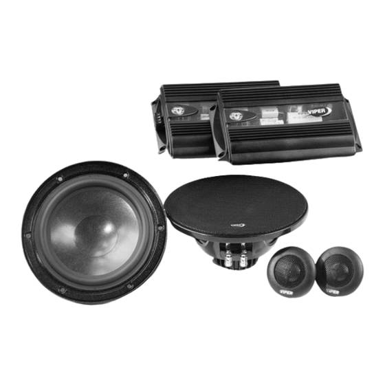
Summary of Contents for Viper 650.2
- Page 1 550.2 models 650.2...
- Page 2 © 2002 Directed Electronics, Inc...
-
Page 3: Table Of Contents
Directed Electronics has been the industry leader in high-quality automo- tive security and audio equipment since 1990, and with the introduction of the Viper Audio line of high-quality loud- speakers for the automobile, Directed continues to set new standards of performance, reliability, and affordability in the mobile electronics industry. -
Page 4: Limited Two-Year Consumer Warranty
LIMITED TWO-YEAR CONSUMER WARRANTY Directed Electronics, Inc. (DEI) promises to the original purchaser, to replace this product should it prove to be defective in workmanship or material under normal use, for a period of two years from the date of purchase from the dealer as indicated by the date code marking of the product PROVIDED the product was installed by an authorized... -
Page 5: Features
Standard stereo and bi-wire inputs with input parallel switch. Glass epoxy PCB for better system power handling. Unique, Viper amplifier-styled crossover housing with removable trim panel for easy switch access. They may also impair a driver’s ability to hear traffic sounds or emergency vehi- cles. -
Page 6: Sound Quality
Undersized holes can cause speaker designing and installing an auto sound system. To achieve the best sound quality possible from your Viper Audio loud- speakers, Directed recommends the installation be performed by an MECP certified technician. distortion or shorting of the speaker leads to the chassis ground. -
Page 7: Woofer Installation
The 550.2 woofer requires a 4-7/8" hole The 650.2 woofer requires a 5-3/4" hole. 3. Remove the cutout template and carefully cut the speaker hole to the proper size. If there is a pre-existing hole that is undersize, mark it and cut it to the proper size. -
Page 8: Tweeter Installation
6. Align the tweeter so the Viper logo faces the desired direction then push the pressure ring on to the rear of... - Page 9 Flush Mounting into Mounted Panels 1. Determine the tweeter mounting location, then route the wires from the crossover to the tweeter loca- tion. 2. Mark the center point of the tweeter location. 3. If using a hole saw, first drill a pilot hole, then cut out the hole using a standard 2-1/8"...
- Page 10 Tweeter Surface Mounting 1. Determine the tweeter mounting location, then route the wires from the crossover to the tweeter loca- tion. 2. Place the surface mount housing against the panel and mark the two holes at the rear of the housing. 3.
-
Page 11: Crossover Installation
Review the Installation Precautions section of this guide before proceeding. Crossover Adjustment and Wiring Connections This Viper crossover has the ability to work in car audio systems from basic single amplifier systems to the most sophisticated multiple amplifier systems with signal processors and amplifier chan- nels dedicated to each speaker. - Page 12 Connection/Adjustment Single Amplifier 1. Connect the amplifier channel output to the crossover input connector as shown, carefully observing amplifier output polarity. FIGURE 5—SINGLE AMPLIFIER 2. Connect the tweeter and woofer wires to the output connector as shown, carefully observing speaker polarity.
- Page 13 Connection/Adjustment Dual Amplifier 1. Connect the amplifier tweeter and woofer channel outputs to the crossover input connector as shown, carefully observing amplifier output polarity. FIGURE 6—DUAL AMPLIFIER © 2002 Directed Electronics, Inc 2. Connect the tweeter and woofer wires to the output connector as shown, carefully observing speaker polarity.
-
Page 14: Specifications
S S y y s s t t e e m m E E f f f f i i c c i i e e n n c c y y i i n n d d B B 550.2 650.2 Tweeter 71.1... - Page 16 Directed Electronics, Inc. Vista, California 92083 www.directed.com Quality Directed products are sold and serviced throughout North America and around the world Call 800 274 0200 for more information about our products and services © 2002 Directed Electronics, Inc. - All rights reserved - G36055/65 02/02 The company behind this system is Directed Electronics, Inc.
Need help?
Do you have a question about the 650.2 and is the answer not in the manual?
Questions and answers