Table of Contents
Advertisement
Quick Links
1LAN-SDAN-8293
Software Defined
Access Node
Quick Installation Guide
SD-LAN-000-8293
General Information |
•
The 8293 Access Node consists of the ONT, including the DC connector and mounting screws.
•
This document describes how to install the ONT, mount the ONT, DC wiring connection, and fiber
connection.
Items Required For 8293 Installation |
The following included items are required for installing the 8293. If any of the listed items are missing, contact our
Corning representative.
8293 Access Node
1LAN-SDAN-8293
Mounting Screws 4
DC Terminal Block; two pole with screw for
wire (PN: 255760003)
QUICK INSTALLATION SHEET I SDLAN-000-8293 I APRIL 2018 I
Table 1 Required items for 8293 Installation
Quantity
1
4
1
Item
Page 1
Advertisement
Table of Contents

Subscribe to Our Youtube Channel
Summary of Contents for CORNING 1LAN-SDAN-8293
- Page 1 1LAN-SDAN-8293 Software Defined Access Node Quick Installation Guide SD-LAN-000-8293 General Information | • The 8293 Access Node consists of the ONT, including the DC connector and mounting screws. • This document describes how to install the ONT, mount the ONT, DC wiring connection, and fiber connection.
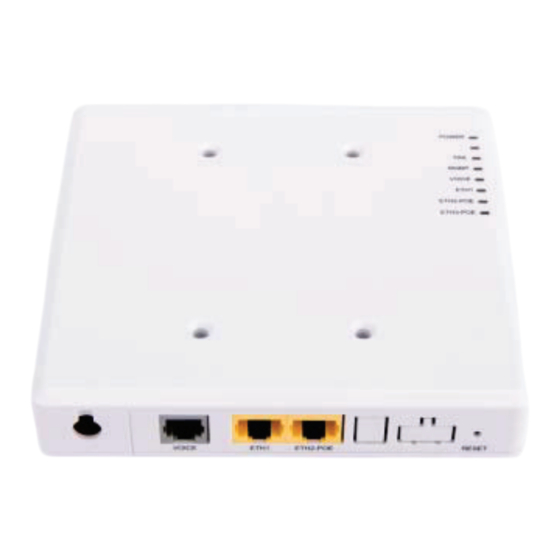
- Page 2 1LAN-SDAN-8293 Software Defined Access Node Quick Installation Guide 1 Connections and Ports | Figure 1 8293 Access Node Ports and Connections PORTS • PoE+ Ethernet ports – 2 (RJ-45) 30 W PoE+ total between both ports • Ethernet Port – 1 (RJ-45) •...
- Page 3 1LAN-SDAN-8293 Software Defined Access Node Quick Installation Guide 2 USING SURFACE MOUNT CRADLE (1LAN-SDAN-SMCRD) | Step 1 Using 2 screws provided, attach cradle to mounting surface using two screw holes in back of cradle. If entering the cradle from side, remove...
- Page 4 1LAN-SDAN-8293 Software Defined Access Node Quick Installation Guide 3 USING SURFACE MOUNT CRADLE (1LAN-SDAN-SMCRD) | Step 1 Mount Dual gang box securely in wall. Route cable inside box in a mannerthat Step 2 maintains bend radius andprevents cable from being pinched or damaged.
- Page 5 Notes: Fiber can be terminated using: A. Unicam® Connectors B. Fuselite® Connectors C. Fusion Spliced Pigtail METHOD A. Unicam® SC/APC Connector | Step 1 Terminate fiber using Corning Unicam® standard recommended procedure (https://www.corning.com/catalog/coc/documents/standar d-recommended-procedures/006-369.pdf Remove port cover. Step 2 Plug SC/APC connector into fiber port on ONT (Figure 8).
- Page 6 1LAN-SDAN-8293 Software Defined Access Node Quick Installation Guide METHOD C. Fusion Spliced Pigtail SC/APC Connector | Step 1 Terminate fiber using SC/APC fusion splice pigtail. Route and secure pigtail fiber and incoming fiber in cradle Step 2 or gang box to make sure it maintains accepted bend radius and fibers are not pinched or damaged.
- Page 7 1LAN-SDAN-8293 Software Defined Access Node Quick Installation Guide 5 DC Wiring Connections | NOTE: The 8293 Access Node can be remote powered with composite cable or local powered with power supply (1LAN- SDANPWRSUP2) Step 1 Identify the positive and negative terminals on the DC connector.
- Page 8 1LAN-SDAN-8293 Software Defined Access Node Quick Installation Guide 6 Power and Operation | Step 1 Connect the copper connections to PSU or use AC/DC Adapter to power (1LAN- SDANPWRSUP2). Verify normal operation when unit is Step 2 powered up and system is configured.
Need help?
Do you have a question about the 1LAN-SDAN-8293 and is the answer not in the manual?
Questions and answers