Advertisement
Table of Contents
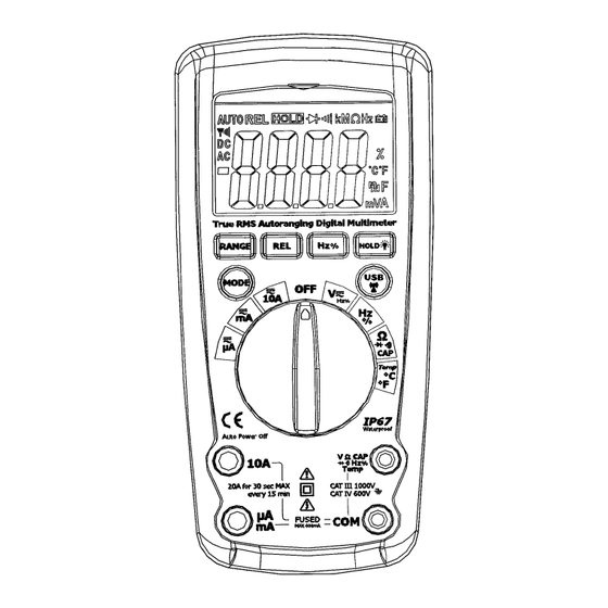
- 1 Symbols and Annunciators
- 2 Operation
- 3 DC/Ac Voltage Measurement
- 4 DC Current Measurement
- 5 Ac Current Measurement
- 6 Resistance [ Ω ] Measurement
- 7 Continuity Check
- 8 Diode Test
- 9 Capacitance Measurement
- 10 Frequency Measurement
- 11 Temperature Measurement
- 12 Specifications
- 13 Battery Installation
- 14 Replacing the Fuses
- Download this manual
Advertisement
Table of Contents

Related Manuals for Jaycar QM1571


Summary of Contents for Jaycar QM1571
- Page 1 QM1571 OPERATING INSTRUCTIONS TRUE RMS AUTORANGING DIGITAL MULTIMETER www.procontechnology.com.au Phone: (03) 98306288...
- Page 2 SAFETY WARNINGS The following safety information must be observed to insure maximum personal safety during the operation at this meter: ♦ Measurements beyond the maximum selected range must not be attempted. ♦ Extreme care must be taken when measuring above 30 VAC or 60VDC, especially on live bus-bars.
- Page 3 ♦ Warnings and precautions must be read and understood before the instrument is used. They must always be observed during the operation of this instrument. Symbols used on this instrument are: Caution: refer to accompanying notes This symbol indicates that the operator must refer to an explanation in the Operating Instructions to avoid personal injury or damage to the meter.
-
Page 4: Symbols And Annunciators
This symbol advises the user that the terminal(s) so marked must not be connected to a circuit which the voltage with respect to earth or ground exceeds (in this case) 1000 VAC or VDC. Equipment protected throughout by Double Insulation (Class III). Equipment complies with current EU directives. -
Page 5: Operation
Direct Current or Voltage Volts A, mA, Amps, milli-Amps, micro-Amps µ OPERATION To turn on the meter rotate the function switch from the OFF position to any measurement position. For best battery life, ALWAYS turn the function switch to the OFF position when the meter is not in use. This meter has an Auto OFF capability that automatically shuts the meter OFF after 30 minutes. - Page 6 HOLD/BACKLIGHT button The HOLD button holds the current display reading until momentarily pressed again. Press and hold this button for more than 2 seconds to turn the backlight on. Press again for more than 2 seconds to turn off the backlight. RANGE button When the function switch is operated, the meter automatically starts operating in Auto Ranging mode.
-
Page 7: Dc/Ac Voltage Measurement
REL button The REL button performs a relative measurement. Except for Hz, %, Diode and Continuity, all other functions will operate in the relative mode. Hz% button Hz% is the Frequency/Duty Cycle select button. In the frequency measurement mode (function switch set to Hz%), pressing the button can select frequency or duty cycle measurements;... -
Page 8: Dc Current Measurement
DC CURRENT MEASUREMENT 1) Insert the black test lead into the negative COM jack. 2) For current measurements up to 4000 A DC, set the µ function switch to the A position and insert the red µ test lead banana plug into the A jack. -
Page 9: Ac Current Measurement
AC CURRENT MEASUREMENT 1) Insert the black test lead into the negative COM jack. 2) For current measurements up to 4000 A AC, set the µ function switch to the A position and insert the red µ test lead banana plug into the A jack. -
Page 10: Resistance [ Ω ] Measurement
RESISTANCE [ Ω ] MEASUREMENT WARNING: To avoid electric shock, disconnect power to the unit under test and discharge all capacitors before taking resistance measurements. 1) Set the function switch to the Ω position. 2) Insert the black test lead into the negative COM jack and the red test lead plug into the positive Ω... -
Page 11: Diode Test
1) Set the function switch to the position. 2) Insert the black lead plug into the COM jack and the red test lead plug into the positive jack. 3) Press the MODE button until " " appears on the display. 4) Touch the test probe tips to the circuit or wire you wish to check. -
Page 12: Capacitance Measurement
semiconductor junction you wish to test. It is best to disconnect one side of the part under test so the rest of the circuit will not interfere with the readings. 5) Reverse the probe polarity by switching probe positions. Note both readings. 6) The diode or junction can be evaluated as follows: A. -
Page 13: Frequency Measurement
3) Touch the test probes across the part under test. 4) Read the capacitance value on the display. FREQUENCY MEASUREMENT 1) Set the function switch to the Hz% position. 2) Insert the black test lead banana plug into the negative COM jack and the red test lead banana plug into the positive Hz% jack. - Page 14 Note: The temperature probe is fitted with a type K mini connector. A mini connector to banana connector adaptor is supplied for connection to the input jacks. PC WIRELESS COMMUNICATION: 1) Install the USB wireless adapter, and launch the software supplied. 2) Press USB to enter the RF wireless transmit mode.
-
Page 15: Specifications
SPECIFICATIONS Technical Specifications: Insulation: Class2, Double insulation. Overvoltage category: CATIV 600V, CAT III 1000V NOTE: This meter meets CAT III and CAT IV IEC 61010 standards. The IEC 61010 safety standard defines four overvoltage categories (CAT I to IV) based on the magnitude of danger from transient impulses. - Page 16 Operating environment: -10°C to 50°C (14°F to 122°F) at <70% relative humidity. Storage temperature: -30°C to 60°C (-4°F to 140°F) at <80% relative humidity Relative humidity: 90% (0°C to 30°C); 75% (30 C to 40°C); 45% (40 C to 50°C) Maximum altitude: Operating: 3000m Storage: 10,000m...
- Page 17 Input Impedance: 10MΩ 1000V DC 1000V AC Maximum Input: AC Voltage (Auto-ranging) Range Resolution Accuracy 400.0mV 0.1mV 4.000V ±1.0% of reading 40.00V 10mV ±3 digits 400.0V 100mV 1000V ±1.2% of rdg ±5 digits All AC voltage ranges are specified from 5% of range to 100% of range Input Impedance: 10MΩ...
- Page 18 Overload Protection: FF500mAI1000V and F10A/1000V Maximum Input: 400µA DC on µA range 400mA DC on mA range 10A DC on 10A range AC Current (Auto-ranging) Range Resolution Accuracy 400.0µA 0.1µA 4000µA 1µA ±1.5% of rdg ±5 digits 40.00mA 10µA 400.0mA 100µA 10mA ±3.0% of rdg ±5 digits...
- Page 19 Resistance [Ω] (Auto-ranging) Range Resolution Accuracy 400.00Ω 0.1Ω ±0.8% of rdg ±5 digits 4.000kΩ 1Ω 40.00kΩ 10Ω ±0.8% of rdg ±2 digits 400.0kΩ 100Ω 4.000MΩ 1kΩ ±2.5% of rdg ±8 digits 40.00MΩ 10kΩ Input Protection: 1000V DC or 1000V AC RMS Capacitance (Auto-ranging) Range Resolution...
- Page 20 40.00Hz 0.01Hz ±1.0% of rdg ±3 dgts 400.0Hz 0.1Hz 4.000kHz 40.00kHz 10Hz 400.0kHz 100Hz 5.00MHz 1kHz ±1.2% of rdg ±4 dgts Sensitivity: >0.5V RMS when ≤1MHz Sensitivity: >3V RMS when >1MHz Input Protection: 1000V DC or 1000V AC RMS Duty Cycle Range Resolution Accuracy 0.1%~99.9% 0.1%...
- Page 21 Overload protection: 1000V DC or AC RMS Diode Test Test current Resolution Accuracy 1mA typical ±10% of reading Max. 1.5V open ±5 digits Open circuit voltage: Max. 1.5V DC Overload protection: 1000V DC or AC RMS Audible continuity Audible threshold: Less than 50Ω Test current max.
- Page 22 BATTERY and FUSE replacement To avoid electric shock, disconnect the WARNING: test leads from any source of voltage before removing the battery cover or opening the meter. 1) When the battery becomes exhausted or drops below the operating voltage, the battery warning " "...
-
Page 23: Battery Installation
BATTERY INSTALLATION To avoid electric shock, disconnect the WARNING: test leads from any source of voltage before removing the battery cover. 1) Disconnect the test leads from the meter. 2) Open the battery cover by removing the two central screws using a Phillips head screwdriver. 3) Remove the cover and insert the battery into battery compartment, observing the correct polarity. - Page 24 two central screws using a Phillips head screwdriver. 3) Remove the pull-out stand and remove the six screws using a good-quality Phillips head screwdriver. Be careful not to lose the screws, washers and rubber seals. 4) Remove the back of the meter with care. 5) Remove the old fuse from its holder by gently pulling it out.
Need help?
Do you have a question about the QM1571 and is the answer not in the manual?
Questions and answers