Kohler OnCue Plus Wireless Kit Installation Instructions Manual
6--60 kw generator sets with rdc2/dc2, vsc, or rdc/dc controller
Hide thumbs
Also See for OnCue Plus Wireless Kit:
- Quick start manual (21 pages) ,
- User manual (44 pages)
Advertisement
Original Issue Date: 6/14
Model: 6- -60 kW Generator Sets with RDC2/DC2, VSC, or RDC/DC Controller
Market: Residential/Light Commercial
Subject: OnCuer Plus Wireless Kits GM62465-KP3-QS and GM81385-KP3-QS
Introduction
The OnCuer Plus Wireless Kit allows wireless
connection of residential/light commercial generator
sets to the owner's wireless router for Internet access.
Use this kit to connect the generator set to the Internet
for the Kohlerr OnCuer Plus Generator Management
System.
The kit uses a wireless access point (AP) to connect the
generator set to the Internet without running a cable
from the owner's router to the generator set. The
wireless AP is installed inside the generator enclosure
and powered by the generator's engine starting battery.
These instructions explain installation and setup of the
wireless AP.
The VHB tape provided with the kit allows installation of
the kit components without drilling additional holes or
using special tools. The ambient temperature must be
warmer than 0_C (32_F) at the time of installation. Once
installed, the tape is rated for --35 to 110_C
(--31 to 230_F).
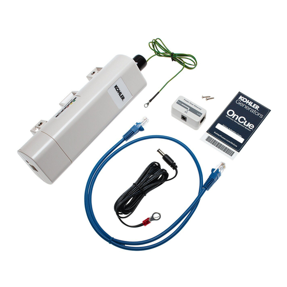
See Figure 1 to identify the correct OnCue Plus wireless
kit for your generator model. See Figure 2 for the
wireless access point (tape not shown).
Special Equipment
The following items are required for installation and
setup.
Wireless router for Internet connection, customer-
D
provided
The customer's wireless network security properties
D
and password are required.
instructions explains how to obtain this information.
Laptop computer (for initial setup only)
D
Network cable for temporary connection of laptop PC
D
to the kit (for initial setup only)
INSTALLATION INSTRUCTIONS
Step 11 of these
Generator Model
14/20RES
6VSG
14/20RESA
38/48/60RCL
Figure 1 Kits and Models
1
2
1. Wireless access point GM91273-1
2. Cable 357477
3. LAN port
4. Power over Ethernet (PoE) box GM91273-3
5. Power cable provided with kit (see Figure 4)
6. PoE port
Note: VHB mounting tape is not shown in this photo.
Figure 2 GM91273 Wireless Access Point
Assembly
TT-1618 6/14
Wireless Kit Number
GM62465-KP3-QS
GM81385-KP3-QS
3
4
5
See Figure 4.
6
tt1618
Advertisement
Table of Contents

Related Manuals for Kohler OnCue Plus Wireless Kit


Summary of Contents for Kohler OnCue Plus Wireless Kit
- Page 1 TT-1618 6/14 INSTALLATION INSTRUCTIONS Original Issue Date: 6/14 Model: 6- -60 kW Generator Sets with RDC2/DC2, VSC, or RDC/DC Controller Market: Residential/Light Commercial Subject: OnCuer Plus Wireless Kits GM62465-KP3-QS and GM81385-KP3-QS Introduction Generator Model Wireless Kit Number 14/20RES GM62465-KP3-QS The OnCuer Plus Wireless Kit allows wireless 6VSG GM81385-KP3-QS connection of residential/light commercial generator...
-
Page 2: Safety Precautions
Safety Precautions radio or television reception, which can be identified by turning the equipment off and on, the user is encouraged Observe the following safety precautions while to try to correct the interference by one of the following performing this procedure. measures: Reorient or relocate the receiving antenna. -
Page 3: Installation Procedure
Installation Procedure generator set model. Make sure the surfaces where the PoE box and access point will be The wireless access point hardware must be installed mounted are clean and dry. inside the generator set enclosure. See Figure 5, Cut one piece of VHB tape approximately 1 inch Figure 6, or Figure 7 for the recommended location on long. - Page 4 Figure 5 Wireless AP Assembly Drawing GM81385, Sheet 1 of 3 TT-1618 6/14...
- Page 5 Figure 6 Wireless AP Assembly Drawing GM81385, Sheet 2 of 3 TT-1618 6/14...
- Page 6 Figure 7 Wireless AP Assembly Drawing GM81385, Sheet 3 of 3 TT-1618 6/14...
-
Page 7: Setup Procedure
Setup Procedure Select Internet Protocol Version 4. Figure 9. A laptop computer with access to the Internet is required Click Properties. to set up the wireless access point. Once setup is complete, the computer is no longer needed. Note: The screen shots shown in this document were created using Windowsr 7. - Page 8 Change the IP address of your Macr Configure the wireless access point. computer to connect to the device. Click the System tab. See Figure 13. Click the Appler icon. Under Basic Settings: change Network Mode to Bridge. Click System Preferences. Click the Apply button to save the settings.
- Page 9 Choose the type of antenna. Connect to the customer’s wireless network. Note: If you are using an external antenna, make sure that you connect the external 11.1 Click on the network icon in the lower right corner antenna to the radio before you enable it. of the screen.
- Page 10 Obtain wireless security settings (if Enter the wireless profile settings. necessary). 13.1 Click on the Wireless tab. 12.1 Click on the Wireless icon in the lower right 13.2 Under Profile Settings: Wireless Network Name corner of screen. See Figure 18. should be the customer’s wireless.
- Page 11 Test the connection (Windowsr PC). 14.5 Select Internet Protocol Version 4. Figure 23. for Mac computer, go to step 15. 14.6 Click on Properties. 14.1 Click on the Windows Start icon in the lower left corner of the screen. See Figure 21. 14.2 Type “network connections”...
- Page 12 Test the connection (Macr computer). Connect the LAN port on the PoE box to the generator set’s network cable. 15.1 Click on the Appler icon. A network cable is provided on the generator set and 15.2 Click on System Preferences. factory-connected to the generator controller.
-
Page 13: Troubleshooting
Troubleshooting Ping Interval and Failure Count The OnCue Plus server is set to notify a customer if a If the device loses connection to your router and does device has lost connection for 1 hour or more. The ping not reconnect on its own, disconnect and reconnect the interval multiplied by the failure count determines the power cable at the DC port on the PoE box. - Page 14 Device Reset Button To confirm proper operation of the Watchdog feature, follow the steps Note: Do not press the reset button on the wireless below. access point. Note: These are temporary settings for this test only. Pressing the reset button will change the IP address of Do not leave this device with these test settings.
-
Page 15: Additional Information
Additional Information Operation Internal Antenna Electrical Specifications Green On = System On Antenna shape Patch array Power Green Off = System Off RF frequency band 2.4 -- 2.5 GHz Amber Blinking = WLAN Activity Power handling Off = No Ethernet Impedance 50 Ohms On = Connection Established... -
Page 16: Parts Lists
14/20RES/L Install Guide WiFi Kit Res/Coml TT-1618 Availability is subject to change without notice. Kohler Co. reserves the right to change the design or specifications without notice and without any obligation or liability whatsoever. Contact your local Kohlerr generator set distributor for availability.
Need help?
Do you have a question about the OnCue Plus Wireless Kit and is the answer not in the manual?
Questions and answers
Is there a remote signal extender available for the Kohler wireless kit?
The provided information does not mention a remote signal extender for the Kohler OnCue Plus Wireless Kit. Therefore, based on the available context, there is no indication that a remote signal extender is included or available.
This answer is automatically generated