Icom IC-4008A Manual
Hide thumbs
Also See for IC-4008A:
- Service manual (31 pages) ,
- Instruction manual (27 pages) ,
- Service manual (38 pages)
Table of Contents
Advertisement
Quick Links
=1
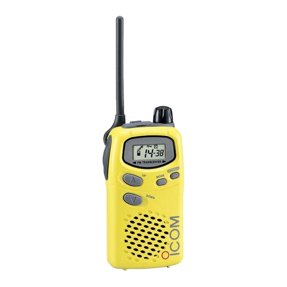
PANEL DESCRIPTION
. Switches, controls, keys and connectors
~
0
ANTENNA
0
SPEAKER
0 ANTENNA
.
Extend the antenna completely when using the transceiver.
The antenna folds completely into the transceiver body for carryin
.
purposes.
The antenna can be adjusted 90 degrees from the regular positiol
when operating the transceiver
f) PH SWITCH [PH]
.
Push and hold to transmit; release to receive.
.
While pushing [PTT], push [POWER] to activate the "PTT hold func
tion". (p.16)
.
.
CHANNEL
UP SWITCH [UP]/[.&]
.
Push to increase the operating channel.
Push and hold to increment the operating channel continuously.
0
CHANNEL
DOWN SWITCH [DOWN]/[~]
.
.
Push to decrease the operating channel.
Push and hold to decrement the operating channel continuously.
0
SPEAKER
0
MODE SWITCH [MODE] (Squelch)
.
Push to toggle between Group mode and Normal mode. (p. 11)
.
Push and hold for 1 sec. to force the squelch open; push and hold for
sec. to close it again. (p. 8)
f) POWERSWITCH[POWER](Key lock)
.
Push to tum the power ON.
.
Push and hold this key for 2 sec. to toggle the key lock functio
ON/OFF. (p. 16)
~
NOTE: Do not push this key for too long when tuming the power m
~
otherwise the key lock function will be tumed ON. (p. 16)
(1) FUNCTION DISPLAY (p. 3)
0 VOLUME CONTROL [VOL]
Rotate clockwise to increase and counterclockwise to decrease volum
4D)EXTERNAL SPEAKER AND MICROPHONE JACKS
Connect an optional speaker-microphone
PANEL DESCRIPTION
in a horizontal position.
or headset, if desired.
Advertisement
Table of Contents

Related Manuals for Icom IC-4008A


Summary of Contents for Icom IC-4008A
- Page 1 PANEL DESCRIPTION PANEL DESCRIPTION . Switches, controls, keys and connectors 0 ANTENNA Extend the antenna completely when using the transceiver. The antenna folds completely into the transceiver body for carryin purposes. The antenna can be adjusted 90 degrees from the regular positiol when operating the transceiver in a horizontal position.
-
Page 2: Function Display
ACCESSORIES PANEL DESCRIPTION . Accessoryattachment . Function display 0 Antenna ~T-T-T-T-~ Adjust the antenna position as I"" shown at right. o-.r ~~ - J CI Keep the jack cover attached , , ~ ...:1 when jacks are not in use to avoid bad contacts. -
Page 3: Battery Pack Charging
BATTERY PACKS BATTERY PACKS . Battery pack charging .Installing batteries in the battery case The optional BP-202 BATTERY PACKincludes rechargeable Ni-Cd batteries and can be charged approx. 300 times. Charge the battery Install 3 AA(R6) size alkaline, dry cell batteries or the BP-202 BAT- pack before first operating the transceiver or when the battery pack TERY PACK as illustrated below. -
Page 4: Charging Connections
BASIC OPERATION BATTERY PACKS . PowerON . Charging connections ~ Rapid charging with the BC-119UBC-119+AD-89 Push [POWER] for 1sec. to turn the Q) Insert the optional AD-89 DESKTOP CHARGER ADAPTER into power ON. the charging slot of the BC-119. The power on indicator and oper- 'The BC-119L comes preinstalled with the AD-89 CHARGING ating channel number appear on ADAPTER. -
Page 5: Selecting The Operating Channel
5111 BASIC OPERATION RECEIVE AND TRANSMIT . Selecting the operating channel Push [UP]/[A] or [DOWN]/["'] keys sev- Push and hold [MODE] 1sec. eral times until the desired operating to open the squelch. Busy indicator TT channel number appears on the dis- Adjust volume to the desired appears. - Page 6 GROUP MODE (CTCSS) CTCSS: Continuous Tone Coded Squelch System . Setting the group code The IC-4008A is equipped with 38 group codes. Group mode op- What is CTCSS (Continuous Tone Coded Squelch Sys- eration provides communication with silent standby since you will...
-
Page 7: Ring Function
0 When no answer comes back, the transceiver emits 3 short tI' Talk Range faint beep tones. The IC-4008A is designed to maximize performance and im- @)Push [PH] to answer and to stop the beeps and flashing. prove transmission range in the field. -
Page 8: Other Functions
OTHER FUNCTIONS OTHER FUNCTIONS 0 PTT hold function . Initial set mode This function frees you from having to constantly push [PTT] during conversation. Initial set mode is accessed at power ON and allows you to set sel- dom changed settings. In this way you can "customize" transceiver While pushing [PTT], push [POWER] operations to suit your preferences and operating style. -
Page 9: Low Battery Indicator
OTHERFUNCTIONS OTHER FUNCTIONS . ATS (Automatic Transponder System) . LCD backlight This allows you to confirm whether or not a call has reached the re- Automatically turns ON for 5 sec. when you push any key, ex- cept [PTT]. ceiving party even if the operator is temporarily away from the transceiver. -
Page 10: Specifications
SPECI FICATIONS OTHER FUNCTIONS GENERAL . Optional HM-75A functions . Frequency c overage: 462.5625-467.7125 MHz The optional HM-75A allows you to remotely select operating chan- . Mode : FM (8K50F3E) nels, open the squelch, etc. The switches on the HM-75A function . - Page 11 1111 MEMO OPTIONS 0 Battery packs . Channel number and group number BP-202 Ni-Cd BATTERY PACK (p. 6-7) 3.6V/700 mAh rapid charge battery pack. Use this page to record your group operating channel number 0 Chargers (see p. 9) and group channel number (p. 11) for your reference. BC-119 DESKTOP CHARGER + AD-89 DESKTOP CHARGER ADAPTER...
-
Page 12: Warranty
2. In order to qualify for warranty service, you must be the original owner repair does not apply to an ICOM FRS radio which, in ICOM America's ex- and the unit returned for service must include proof of purchase (i.e., copy clusive judgment, has failed due to misuse, corrosion, accident, natural dis- of dated invoice).
Need help?
Do you have a question about the IC-4008A and is the answer not in the manual?
Questions and answers