Table of Contents
Advertisement
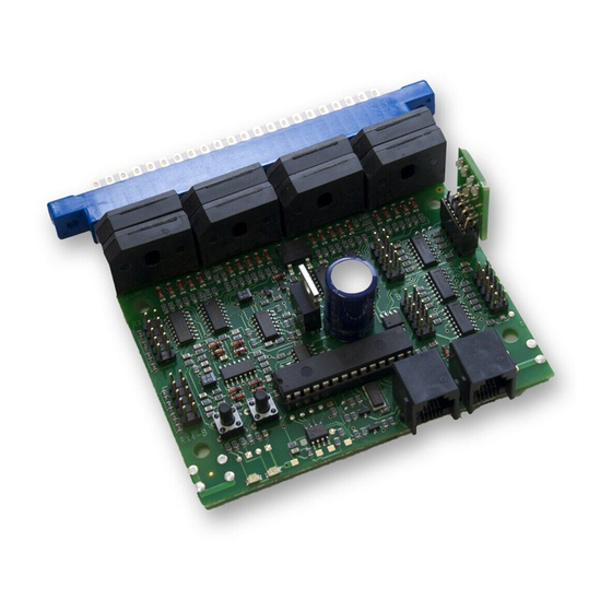
BDL168
LocoNet Occupancy Detector
For 16 Detection Sections and up
to 8 Transponder Zones
F F e e a a t t u u r r e e s s
Occupancy Detection for 16 detection sections lets you know when rolling
n
stock is in a detection section on your layout
Outputs for LEDs to indicate local detection section occupancy and zone
n
power status on a panel mount display
3 Amp capacity per detection section
n
Connect to LocoNet to transmit occupancy information to your LocoNet
n
system
Supports SuperSonic Decoder Operations
n
Detects any powered locomotive
n
Detects un-powered rolling stock equipped with resistor wheel sets
n
Plug and Play with Digitrax DCC
n
Configurable for most DCC systems
n
Automatically checks layout status when computer software is running at
n
layout power on
Improved Rail Sync Sampling for reliable operation
n
Transponding with addition of one or two RX4 Transponder Detectors and
n
transponders in your rolling stock provides additional capabilities:
Identify where specific rolling stock is on your layout
Operations Mode Read Back allows you to read CV values of decoders
equipped with transponders
P P a a r r t t s s L L i i s s t t
1 BDL168
1 44-Pin Connector
The BDL168 requires a 12V-16V AC or DC power supply which is sold sepa-
rately. Multiple BDL16 series detectors can be powered from the same power
supply as long as 100mA is provided for each BDL16 series detector. One
Digitrax PS12 power supply can run up to three BDL16 series detectors.
Digitrax Manuals and Instructions are updated periodically.
Please visit www.digitrax.com for the latest version of all manuals.
©2004 Digitrax, Inc
D D
C C
i i g g i i t t r r a a x x
o o m m m m a a n n d d
R R u u n n Y Y o o u u r r T T r r a a i i n n s s , , N N o o t t Y Y o o u u r r T T r r a a c c k k ! !
www.digitrax.com
C C
o o n n t t r r o o l l
1 LT5 Tester
1 Instruction Manual
All Scales
Advertisement
Table of Contents

Related Manuals for Digitrax BDL168


Summary of Contents for Digitrax BDL168
- Page 1 1 44-Pin Connector 1 Instruction Manual The BDL168 requires a 12V-16V AC or DC power supply which is sold sepa- rately. Multiple BDL16 series detectors can be powered from the same power supply as long as 100mA is provided for each BDL16 series detector. One Digitrax PS12 power supply can run up to three BDL16 series detectors.
-
Page 2: Table Of Contents
Digitrax, LocoNet, Super Empire Builder, Super Chief, Zephyr and others included in this manual are trademarks of various manufacturers including Digitrax. U.S. & International BDL168, RX4, transponding and other Digitrax products & technologies are covered by US Patent #s 6,275,739, 6,220,552, 6,318,678, 6,533,223 and others including patents pending. - Page 3 1 1 . . 0 0 I I n n t t r r o o d d u u c c t t i i o o n n The BDL168 lets you know when a detection section on your layout is occu- pied.
- Page 4 BDL168; this enables 4 transponder zones on the BDL168. In this case, each transponding zone may encompass one to four detection sections. Each BDL168 can host an additional RX4 giving you a total of 8 transponder zones that can be shared across the available 16 detection sections of the BDL168.
- Page 5 The form, BDL16 Series Planning Worksheet, is also available in the same section for documenting your setup for future reference and trouble shooting. Whether you are building a new layout or installing your BDL168 on an exist- ing system, there are two basic wiring formats: direct home wiring and whole layout common wiring.
- Page 6 12V AC UP5s Etc.) Power Power Supply Supply ~ ~ ~ ~ Note: BDL168 Zone A Wiring shown for clarity. Zones B, C, and D are wired similarly. Option LED (red) ID LED (green) DS 16 DS 15 ID Switch...
- Page 7 (Throttles, Boosters, 12V AC 12V AC UP5s Etc.) Power Power Supply Supply Note: For this example, BDL168 OPSW 10 must be set to "c". Option LED (red) ID LED (green) DS 16 DS 15 ID Switch DS 14 DS 13...
- Page 8 The BDL168 wiring panels should be located near the highest feeder density in order to minimize the lengths of wires feeding from the track to the BDL168. Planning the detection sections on the layout and the associated wiring on the wiring panel is covered in more detail in the technical applications paper, Advanced Transponding Application Note, available at www.digitrax.com.
- Page 9 “wink” off once, approximately every 2 seconds, indicating that it is connected to LocoNet and seeing DCC packets. The BDL168's option switches are factory set at the values that will work for most direct home wired layouts. You can fine-tune the BDL168's characteris- tics using its option switches which can be set using a Digitrax compatible throttle or a PC with LocoNet compatible software that can control turnouts.
- Page 10 8. The first time you apply power to the unit, hold down the switch located behind the red LED on the BDL168 to set it up for whole layout common rail operation. The red and green LEDs will light up as power is applied to the unit.
- Page 11 2) Letters G, I, O & Q are not used as pin designations on the connector. 3) Power connections should be made to a power supply dedicated to BDL168 use only. Multiple BDL168 units can be supplied by a single shared supply as long as you provide at least 100mA for each BDL168.
- Page 12 6 6 . . 0 0 B B D D L L 1 1 6 6 8 8 I I n n s s t t a a l l l l a a t t i i o o n n f f o o r r n n o o n n D D i i g g i i t t r r a a x x L L a a y y o o u u t t s s To make set up simpler and easier for non-Digitrax layouts to use the BDL168,...
- Page 13 The option switches and settings you can use to customize your BDL168 are indicated in Table 2. These option switches on your BDL168 are set up using a Digitrax throttle's SWITCH commands. (This can only be done with a Digitrax LocoNet throttle or equivalent software).
- Page 14 Table 2: BDL168 Option Switches (OpSw) The following table shows what each OpSw is used for when it is set for thrown or closed. Factory settings are indicated by shaded boxes. Option Switches for BDL168 and RX4. OpSw t = thrown...
-
Page 15: Direct Home Wiring
GPOFF GPOFF ( * changes only affect transponding) Suggested BDL168 Settings for Railroad&Co. from European users. OpSw9 = Closed (No message sent if un-powered) OpSw36 = Closed (Ignore GPON) OpSw37 = Closed (Long delays for sensors) OpSw38 = Closed (Extra long delay for sensors) - Page 16 NOTE: If a turnout switch number on the layout matches the OpSw number being set during this process, the turnout will be activated during the OpSw setting. Once the BDL168 OpSw configuration is completed and you have exit- ed option switch setup mode (See section 7.1, Step 5), simply reset the turnout to the desired position.
-
Page 17: Bdl168 Board Address
BDL168. Press the key until the corresponding LED is lit. This will set the board address for the BDL168. The green LED will then go steady green to indicate BDL168 Power ON. When you are finished... - Page 18 Figure 5: Reversing Section Wiring Example ©2004 Digitrax, Inc www.digitrax.com...
-
Page 19: Power Management
If a device is used to switch off power feeding the BDL168 and the track it is connected to, for example, a PM42 Power Manager, it should break the track power to both the zone and detection common rail. -
Page 20: Panel Indicator
3mA. If you use higher LED drive currents you can use external transistors etc to amplify the LED current. The LED drive from the BDL168 is active high at about +5 volts above the BDL168 ground pin, via a 1 Kohm resistor. Note that the ribbon cable includes separate ground return conductors for each LED that allow a 10 conductor rib- bon cable to be split into 5 pairs to conveniently route to individual LEDS. - Page 21 ©2004 Digitrax, Inc www.digitrax.com...
-
Page 22: Packet Reception
1 1 2 2 . . 0 0 T T r r a a n n s s p p o o n n d d i i n n g g w w i i t t h h t t h h e e B B D D L L 1 1 6 6 8 8 The BDL168 is ready to set up eight transponding zones with the addition of one or two RX4 Transponder Detectors. -
Page 23: Loconet Debug
4 occupancy LED headers on the BDL168 and solder LEDs to the wires to create an array of LEDs (see Figure 6). By plugging this display array into one of the 4 occupancy LED headers (Figure 5, marked A,B,C &... - Page 24 All warranties on Digitrax products are limited to refund of purchase price or repair or replacement of Digitrax products at the sole discretion of Digitrax. In the event that Digitrax products are not installed or used in accordance with the manufacturer's specifications, any and all warranties either expressed or implied are void.
- Page 25 BDL168 LocoNet Occupancy Detector 450 Cemetery Street #206 Norcross, GA USA 30071 www.digitrax.com 770-441-7992 770-441-0759 Made in U.S.A. sales@digitrax.com...
Need help?
Do you have a question about the BDL168 and is the answer not in the manual?
Questions and answers