Advertisement
Quick Links
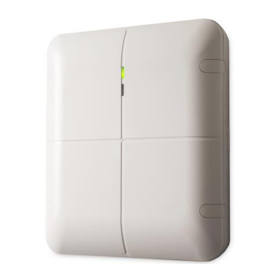
ioXpander-12x4 Module
1. Introduction
This installation guide provides the basic instructions for Visonic's ioXpander-12x4 Module installation scenarios. A
new addition to the PowerMaster-33 E G2 control panel, the ioXpander-12x4 Module is a wired input/output expander
that communicates with the PowerMaster-33 E G2 through the ioXpander-8 module.
ioXpander-12x4 Module Features:
12 wired inputs that enable to connect to 12 H/W zones
4 relay outputs.
Siren output (SRN) and Strobe output (STR)
Front and back cover tamper switches for improved tamper protection
RS-485 bus to communicate with the panel
The ioXpander-12x4 Module is supported by the PowerMaster-33 E G2 only
Terminology:
1.1
Abbreviation
Definition
NO / NC
Normally Open / Normally Closed
EOL/DEOL
End of Line / Double EOL
HW-Zone
Hard wired zone
ioXpander-8
Expander and bus controller on the PowerMaster-33 E G2
PGM
Programmable Relay Output
PCB
Printed circuit board
2. General Guidelines
1. Keep away from all heat sources.
2. Do not expose to air drafts.
3. Do not install outdoors.
4. Avoid direct sunshine.
5. Keep wiring away from power cables.
6. Mount on solid stable surfaces.
IMPORTANT: The ioXpander-12x4 Module MUST BE POWERED
DOWN while wiring the I/Os and when connecting to the RS-485 bus.
This will prevent accidental damage to the device.
www.visonic.com
Installation Guide
Page 1 of 11
D-306783 ioXpander-12x4 Module
(Rev 2, 11/17)
Advertisement

Related Manuals for Visonic ioXpander

Summary of Contents for Visonic ioXpander
- Page 1 This installation guide provides the basic instructions for Visonic’s ioXpander-12x4 Module installation scenarios. A new addition to the PowerMaster-33 E G2 control panel, the ioXpander-12x4 Module is a wired input/output expander that communicates with the PowerMaster-33 E G2 through the ioXpander-8 module.
- Page 2 3. Installing the ioXpander-12x4 Module The ioXpander-12x4 Module enclosure provides tamper detection and accessible wiring cavities. 1. To open the front cover: remove screws on the 3. Remove the securing screw and push the sides, place fingers in the opening grove of each tab to release the PCB with the interface.
- Page 3 Thread the cables screws on both sides inside the box through the cable cavities and connect as needed to the terminal blocks. Tamper Cap Page 3 of 11 www.visonic.com D-306783 ioXpander-12x4 Module (Rev 2, 11/17)
- Page 4 4. Configuration The PowerMaster-33 E G2 can support up to 4 ioXpander-12x4 Modules for a total of 48 wired zones. Every ioXpander-12x4 Module is connected and registered to the ioXpander-8 module using a RS-485 bus (230000 bps). The ioXpander-12x4 has two LEDs Green Power - Lights continuously when powered.
- Page 5 The first 8 outputs are reserved for the ioXpander-8 Module. The other 8 outputs (PGM9 – PGM16) can be distributed among the ioXpander-12x4 Module. The installer needs to enroll each PGM output to the required output pin of the required ioXpander-12x4 Module. For more information refer to section 6: “Enrollment Process.”...
- Page 6 12Vdc and rated current of __1__a max. Both the CP and PS that are used for powering the ioXpander-12x4 Module must be EN 50131-6 certified. The loads that can connect to the relay outputs must be limited to a maximum of 12 VDC, 8A or 24 VDC, 4A! Example of ioXpander-12x4 Modules connected to external power supply with 12 hour backup battery.
- Page 7 Module Circuit Board: Page 7 of 11 www.visonic.com D-306783 ioXpander-12x4 Module (Rev 2, 11/17)
- Page 8 Note: The ioXpander-12x4 Module has no Location or Device Settings that need programming. Note: Only after the ioXpander-12x4 Module is enrolled can its Inputs (Step 6) and Outputs (Step 7) be enrolled. Step 6 - Pre-enroll an HW-Zone to a ioXpander-12x4 Module's Input To define a HW-Zone onto a ioXpander-12x4 Module: On the Keypad, select the “ADD NEW DEVICE”...
- Page 9 Cautions- If an enrolled ioXpander-12x4 Module does NOT communicate with the PowerMaster-33 E G2 (whether it is powered OFF, not connected, or for any other reason), the following is displayed on the KP-250 screen: "Expander IOV E0x MISSING", it must be deleted at once by the Installer.
-
Page 10: Product Specifications
Product offerings and specifications are subject to change without notice. Important Shipment Information: The ioXpander-12x4 Module PGM Terminal Blocks are labeled in two different ways. There is no difference in their functionality. The only difference is how the PGM’s PCBs are labeled. - Page 11 Thi s devi c e c om pli es wi th EN 50131 -3 G rade 2, C l as s II Visonic Limited (the “Manufacturer") warrants this product only (the The Manufacturer shall be under no liability whatsoever arising out of the "Product") to the original purchaser only (the “Purchaser”) against defective...
Need help?
Do you have a question about the ioXpander and is the answer not in the manual?
Questions and answers