Table of Contents
Advertisement
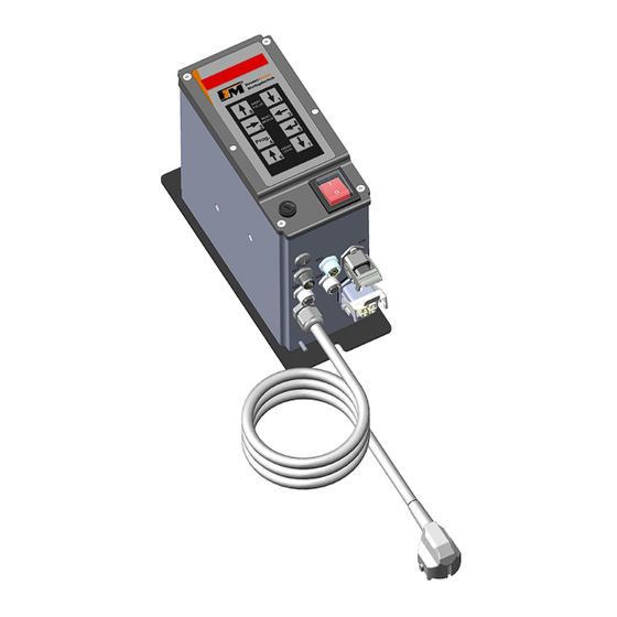
Operating instructions FS-26
Operating instructions
Frequency control devices FS-26
for vibratory conveyors
Art. no.: 90.0210.60
fimotec-fischer GmbH & Co. KG
Friedhofstraße 13
D -78588 Denkingen
Tel:
+49 (0)74 24 - 88 4-0
Fax:
+49 (0)74 24 - 88 4-50
E-mail:
post@fimotec.de
Internet:
www.fimotec.de
Status as of 11 / 2019
-
Page 1
Advertisement
Table of Contents

Summary of Contents for fimotec-fischer FS-26
- Page 1 Operating instructions FS-26 Operating instructions Frequency control devices FS-26 for vibratory conveyors Art. no.: 90.0210.60 fimotec-fischer GmbH & Co. KG Friedhofstraße 13 D -78588 Denkingen Tel: +49 (0)74 24 - 88 4-0 Fax: +49 (0)74 24 - 88 4-50 E-mail: post@fimotec.de...
- Page 2 Users are obligated to comply with all applicable copyright laws. No part of these documents can be duplicated or transmitted without the express written permission from fimotec-fischer GmbH & Co. KG, independent of how or by what means (electronically or mechanically) this occurs.
-
Page 3: Table Of Contents
Operating instructions FS-26 Table of contents 1 General The product Guide for these instructions Safety-related information for the user Intended use 2 Application 3 Installation Overview and dimensions Connections / operating elements of control boards Housing connections 4 Commissioning Control panel... -
Page 4: General
Operating instructions FS-26 General In this manual, you will find all important information regarding the mounting, connection, setting and operation of your FS 26 device. In addition, you will find information as well as important warnings for your safety. Please observe: Devices of the FS 26 series are specially adapted frequency converters for the actuation of vibratory conveyors. -
Page 5: Safety-Related Information For The User
Operating instructions FS-26 Safety-related information for the user These instructions contain the required information for the intended use of the device described herein. They are directed toward technically qualified personnel. Qualified personnel are people who have been authorized by persons responsible for the safety... -
Page 6: Intended Use
Operating instructions FS-26 Operation The control device only functions correctly when it is correctly installed and operated. In the event of malfunctions or unclear operating states, you should check the device and remedy the malfunction (see "Error list" chapter) or have it remedied. -
Page 7: Application
Operating instructions FS-26 Application The electronic frequency converter FS 26 is used for the infinitely variable control of inductive loads, such as spiral conveyors, linear conveyors and hoppers. The device works according to the principle of pulse width modulation within the half-waves with adjustable periods of 5 - 200 Hz;... -
Page 8: Installation
Operating instructions FS-26 Installation A bore and elongated hole, externally accessible in the center of the device axis, are available for fastening the device. These are separated from the device interior. Important note Fasten the device to a vibration-free surface. -
Page 9: Overview And Dimensions
Operating instructions FS-26 Overview and dimensions M12x1.5 Blind plug M12 plug, 4-pin, for enable input connection (E1) – X21 M12 socket, 4-pin, b-coded, for status output connection (T1) – X23 M12 socket, 4-pin, for sensor input connections (E2+E3) – X22... -
Page 10: Connections / Operating Elements Of Control Boards
Operating instructions FS-26 Connections / operating elements of control boards Status as of 11 / 2019 Page 10... -
Page 11: Housing Connections
Operating instructions FS-26 Housing connections Vibratory conveyor connection Pin 1 - Load Pin 2 - Load Pin 3 - Not Connected - Protective conductor Mains voltage connection Pin 1 - L Pin 2 - N - Protective conductor Control input connection E1... -
Page 12: Commissioning
Operating instructions FS-26 Commissioning Before connecting the device, the mains voltage and frequency must be determined. The data must lie in the range of permissible values for the device. Check and set the jumpers according to the control type. Connect the vibratory conveyor and control cable to the control device. -
Page 13: Control Panel
Operating instructions FS-26 Control panel The device is operated/set via 8 keys which are located on a control panel on the cover, together with a 6 x7-segment LED display. All operating mode settings as well as the settable parameters can be made via this control panel. - Page 14 Operating instructions FS-26 Keypad explanation The parameters are set by means of a menu structure and by entering an operator code. In the "Setting instructions", the menu structure and the setting ranges of the parameters, as well as the function programming, will be explained.
-
Page 15: Menu Structure
Operating instructions FS-26 Procedure example: Select level via 6 and 7 keys. Select parameter via 2 and 3 keys. Press the 4 key to get into programming mode. Enter the operator code (except for the "Amplitude" parameter), A or B. -
Page 16: Level 0 - Performance Parameter, Vibratory Conveyor Drive
Operating instructions FS-26 LEVEL 0 - Performance parameter, vibratory conveyor drive After power ON, the display switches to the "Amplitude" root display. Depending on this, the 2 and 3 keys can be used to roll to every individual parameter on this level. The following parameters are available:... - Page 17 Operating instructions FS-26 Parameter: Setpoint specification [function] Code A and B Value can be set to F, I, P, U, b F - Setpoint specified via membrane keypad I - Setpoint specified via analog current 4 - 20 mA= P - Setpoint specified via potentiometer 10K...
- Page 18 Operating instructions FS-26 Parameter: Parameter backup [function] Code A and B Value can be set to 0, bs, br, rE No function bs - Save backup parameters br - Load backup parameters rE - Load factory settings Parameter: Nominal acceleration [g] Code A and B Value can be set from 0.0 - 20.0...
-
Page 19: Level D - Information Output (Display Only)
Operating instructions FS-26 LEVEL d - Information output (display only) After power ON, the display switches to the "Amplitude" root display. From here, the 6 key can be used to change to level d. The following values and status displays are available: Value: Mains voltage [V~] The currently applied mains voltage is displayed. - Page 20 Operating instructions FS-26 Error number is displayed. Value of applied analog voltage [V=] Value of applied analog current [mA=] Value of current acceleration [g] Depending on the programmed setpoint specification (parameter AE), the applied analog value is displayed here. LEVEL 1 - Enable input E1 After power ON, the display switches to the "Amplitude"...
-
Page 21: Level 2 - Sensor Input E2
Operating instructions FS-26 LEVEL 2 - Sensor input E2 After power ON, the display switches to the "Amplitude" root display. From here, the 6 key (press 3x) can be used to change to level 2. The following parameters are available: A logical 1 causes a reaction. -
Page 22: Level 3 - Sensor Input E3
Operating instructions FS-26 LEVEL 3 - Sensor input E3 After power ON, the display switches to the "Amplitude" root display. From here, the 6 key (press 4x) can be used to change to level 3. The following parameters are available: A logical 1 causes a reaction. -
Page 23: Level 0. - Logic, Vibratory Conveyor Drive
Operating instructions FS-26 LEVEL 0. - Logic, vibratory conveyor drive After power ON, the display switches to the "Amplitude" root display. From here, the 6 key (press 5x) can be used to change to level 0. On level 0, the control of the vibratory conveyor (physical) and the feedback of the vibratory conveyor status (logical) are defined and set. - Page 24 Operating instructions FS-26 Parameter: Logic [function] Code A and B Value can be set to O, U, S Result = physical state of the vibratory conveyor before the function F1 . O - OR operation of all available and active (value entry 0.LEX=1) inputs and active (0.LAX=1) outputs...
-
Page 25: Level 1. - Logic, Transistor Output
Operating instructions FS-26 Parameter Output A3 [funktion] Code A und B Value can be set to 0 or 1 0 - Output switched to inactive (not considered in the logic) 1 - Output switched to active (considered in the logic) - Page 26 Operating instructions FS-26 Parameter: Dropout delay S1 [s] Code A and B Value can be set from 0.0 - 9.9 Increment 0.1 s Depending on the physical state of the transistor output and the inversion by F2, a logical result is output.
-
Page 27: Level 2. - Logic, Transistor Output
Operating instructions FS-26 Parameter: Input A0 [function] Code A and B Value can be set to 0 or 1 0 - Input switched to inactive (not considered in the logic) 1 - Input switched to active (considered in the logic) - Page 28 Operating instructions FS-26 Parameter: F2 [function] Code A and B Value can be set to O, S Function has a direct influence on the logically further processable state of the transistor output (inversion of the logical state). O - Applied HI signal is not inverted and is further processed as logical 1.
-
Page 29: Level 3 - Setting The Amplitude
Operating instructions FS-26 Parameter: Input E2 [function] Code A and B Value can be set to 0 or 1 0 - Input switched to inactive (not considered in the logic) 1 - Input switched to active (considered in the logic) - Page 30 Operating instructions FS-26 4.12 Amplitude adjust After power ON, the display changes to the root display Amplitude Press key 4 to switch to the programming mode. A dot appears in LED 2 from the left. The amplitude can be changed immediately without entering a CODE.
-
Page 31: Safely Setting Up The Vibratory Conveyor
Operating instructions FS-26 4.13 Set up vibratory conveyors safely Zuerst müssen folgende Anschlusswerte des Schwingförderers festgestellt werden: Maximal zulässige Spannung [V~] Maximal zulässige Stromaufnahme [A~] Betriebsfrequenz [Hz] der eingesetzten Wechselstromschwingmagnete Anhand der festgestellten Werte müssen jetzt die zulässigen Arbeitsgrenzen ohne den angeschlossenen Förderantrieb eingestellt werden (Schwingamplitude 30...80V~). -
Page 32: Setting Up The Enable/Sensor Input
Operating instructions FS-26 hoch eingestellter Amplitude es zum Anschlagen des Antriebs kommen kann. Die Resonanzfrequenz stellt sich ein bei maximaler Schwingamplitude und minimalem Ausgangsstrom. Der Strom kann entweder über die eigene Stromanzeige des Gerätes abgelesen werden oder man verwendet ein externes Dreheiseninstrument. - Page 33 Operating instructions FS-26 Parameterize the menu item F1 on levels 1 - 3 with the desired function value via the control panel by changing to programming mode in menu item F1 first (see control panel and operator code): Start in "Amplitude" root display...
-
Page 34: Factory Settings / Read/Save User Backup
Operating instructions FS-26 4.15 Factory settings / read/save user backup Via the control panel, activate the menu item 0old on level 0. Change to programming mode (see the control panel and operator code): Start in "Amplitude" root display To load the factory settings, select the menu item "re". Proceed analogously to saving. -
Page 35: Setting Up External Setpoint Specification
Operating instructions FS-26 4.16 Setting up external setpoint specification Connect the external setpoint to the available connection terminal on the control board via the available bore: Terminal 6 - +5 V= analogous for external potentiometer Terminal 5 - Voltage input 0-10 V=... -
Page 36: Connecting Transistor Outputs
Operating instructions FS-26 4.17 Connecting status/valve output There are two 24V= transistor outputs available for control tasks. Connect them to the available connection sockets, depending on the application. Use a matching mating connector for this. Status output connection T1 (b-coded) -
Page 37: Readjustment With Acceleration Sensor
Operating instructions FS-26 Readjustment with acceleration sensor For regular operation, an acceleration sensor mounted to the vibratory conveyor is required. A supply voltage of +24V= is available. Sensors with an analog voltage output up to 6 V~ or analog current output up to 20 mA= can be connected. -
Page 38: Connecting The Acceleration Sensor
Operating instructions FS-26 Example with circular conveyor Schwingendes Teil Montageblock Sensor Schwingrichtung Festes Teil Example with linear conveyor 1. Small amplitude when mounted vertically 2. Greater amplitude when mounted at the same angle of inclination as the springs The control device and the sensor fastened to the conveyor form a closed control circuit, whereby the signal provided by the sensor has a decisive influence on the control range of the nominal value, i.e., the... -
Page 39: Parameters For The Control Circuit On Level 0
Operating instructions FS-26 Parameters for the control circuit on LEVEL 0 Parameter: Acceleration sensor selection Code B Value can be set to 0, U, I 0 - No acceleration sensor connected Visible after code input U - Acceleration sensor connected to voltage output I - Acceleration sensor connected to current output If a sensor type is activated, the menu for the setpoint specification is supplemented with menu item b. -
Page 40: Technical Data For Acceleration Sensor
Operating instructions FS-26 Program parameter 0t< with read-off value. Leave parameter 0t> at 0.00 for maximum control range. Reset amplitude for optimum running. Teach parameter nominal acceleration 0t (press 0 and 1 keys simultaneously). The current g value is accepted. -
Page 41: Technical Data
Operating instructions FS-26 Technical data Mains connection, wide range 95 - 250 V~ Output voltage ranges Automatic switching between 1 - 230 V~ 1 - 115 V~ Mains frequency 50 Hz 60 Hz Variable output frequency 5.0 - 200 Hz Output current 0.1 - 6 A~... -
Page 42: Setting Values Via Keypad
Operating instructions FS-26 Setting values via keypad Parameter Delivery state Vibratory conveyor, level 0 Vibration amplitude 1...230 V~ 30 V~ Min. control limit 0A> 1...230 V~ 30 V~ Max. control limit 0A< 1...230 V~ 230 V~ Current limit 0.1...10 A~... - Page 43 Operating instructions FS-26 Control level 1 Invert input PNP (O) PNP inverted (S) Debouncing time 0.1...99.9 ms 0.1 ms Control level 2 Invert input PNP (O) PNP inverted (S) Pick-up delay 0.0...9.9 s 2.0 s Dropout delay 0.0...9.9 s 2.0 s Debouncing time 0.1...99.9 ms...
-
Page 44: Error List
Operating instructions FS-26 Logic operation O - OR U - AND S - ACCUMULATION For input which can be activated with logic 2.LE1 Inactive (0) / active (1) For input which can be activated with logic 2.LE2 Inactive (0) / active (1) For input which can be activated with logic 2.LE3... -
Page 45: Error Messages / Error
Operating instructions FS-26 Error messages / ERROR If the complete display is flashing, an error occurred. The error code can be queried on level d under the parameter Err. The following error codes are possible: Connected acceleration sensor is defective or not connected (in regular operation only) Overload shutdown, output power exceeded, e.g., incorrect frequency... -
Page 46: Maintenance And Cleaning
The control device FS26 is marked with the CE marking and therefore meets the relevant European directives. The company fimotec-fischer GmbH & Co. KG herewith confirms that this device meets the following directives: EN 61000-6-4 and EN 61000-6-2 in acc. with ... -
Page 47: Accessories (Not Included In The Scope Of Delivery)
Operating instructions FS-26 Accessories (not included in the scope of delivery) Designation Article number Oscillation amplitude sensor SWS-02 for control device FS-26 90.1130.04 Mounting bracket for vibration amplitude sensor 98.1130.00 Connection cable VK10-3M/VZ/HFA 91.4301.00 Connection cable VK10-1.5M/VZ/HFA 91.4301.20 Connection cable VK10-5M/VZ/HFA 91.4301.10...
Need help?
Do you have a question about the FS-26 and is the answer not in the manual?
Questions and answers