
Summary of Contents for ATS Maximus MXS2000 Series
- Page 1 Your Trusted Partner for Time and Attendance Terminals and Integrated Solutions Reference Manual Maximus Reference Manual Part Number: MANU-MAXIMUS-02 Revision-02...
- Page 2 Revision History Revision Date Description 02/10/2015 Extensive revision to previous documents requiring new Part Number. 04/20/2015 Added WiFi security protocol note on page page 3-34 and added “Configuring WiFi" Chapter 4, “Color Terminals.” 08/27/2015 Graphic changes to the cover. Trademarks Accu-Time Systems and the Accu-Time logo are registered trademarks of Accu-Time Systems, Inc.
-
Page 3: Table Of Contents
Table of Contents Contents Preface Document Conventions ....................P-3 Text Conventions......................P-3 Control Character Representation................P-4 Command Format ...................... P-4 Note & Warning Formats ....................P-5 Notes ......................... P-5 Warning Formats......................P-5 Chapter-1 Terminal Description Maximus Overview ......................1-3 Programming the Terminal ..................1-3 Maximus Features...................... - Page 4 Power Up ........................3-4 Initial Setup ........................3-5 Initial Setup Menu Navigation ................... 3-5 Initial Setup Parameters ..................... 3-7 ATS TSD Mode ......................3-13 Using the TSD Mode....................3-14 ATS Setup Mode ......................3-15 Setup Mode Parameters................... 3-16 Re-Boot ........................3-16 Setup Password .......................
- Page 5 Appendix-A Biometrics ......................A-1 Why Use Biometrics? ......................A-3 User Confidentiality ....................A-3 Reliability Rules......................A-3 ATS Biometric Operational Options................A-4 Verification and Identification Modes ................A-5 Verification Mode...................... A-5 Identification Mode ....................A-5 How it Works ........................A-6 Recommended Fingers ....................A-7 Fingerprint Scanner Types .....................A-8...
- Page 6 Table of Contents Appendix-C Using the USB ....................C-1 Overview ......................... C-3 What You Need......................C-3 Functions........................C-3 Applying a Download ....................C-4 Storing Punches ......................C-5 Updating UCS ......................... C-7 Using a USB Keyboard with the Terminal ..............C-8 Appendix-D GSM/GPRS Setup....................
-
Page 7: Preface
Preface Preface Purpose ® This manual describes the Maximus terminal. It tells you how to install, set up, and test a Maximus terminal, and how to get firmware version information from the terminal to help diagnose a problem if one occurs. Intended Audience You should read this manual if you are responsible for the installation or operation of a Maximus terminal. - Page 8 This page intentionally left blank. Maximus Reference Manual MANU-MAXIMUS-02 Revision-02...
-
Page 9: Document Conventions
Document Conventions Document Conventions The sections below explain the conventions used to present information in this manual. Text Conventions Table P-1 lists the text conventions used in this document (manual). Document Text Conventions Table P-1 Convention Description Subscripts Subscripts indicate the base of a number. For example, 28 is 28 base 10, and 3F is 3F base 16. -
Page 10: Control Character Representation
Document Conventions Control Character Representation The syntax of UCS commands includes some non-printing control characters (character codes 000 to 031 , 000 to 1F ) plus the space character. These non-printing characters and the space character are represented in this manual in various ways as shown in Table P-2. -
Page 11: Note & Warning Formats
Note & Warning Formats Note & Warning Formats This section describes the note and warning formats used in this document (manual) and the circumstances to which they apply. Notes Important information and tips appear as notes. Notes have a special format and appearance. The following is an example of the note format: NOTE: This is how a note appears in this document. - Page 12 Note & Warning Formats This page intentionally left blank. Maximus Reference Manual MANU-MAXIMUS-02 Revision-02...
- Page 13 Terminal Description Chapter About this Chapter This chapter provides an overview of the Maximus terminal and lists its Part Numbers and specifications. Chapter Contents This chapter contains the following topics: Maximus Overview ......................1-3 Maximus Features ....................1-3 Specifications ........................1-5 Part Numbers and Options ....................
- Page 14 Chapter 1: Terminal Description This page intentionally left blank. Maximus Reference Manual MANU-MAXIMUS-02 Revision-02...
-
Page 15: Chapter-1 Terminal Description Maximus Overview
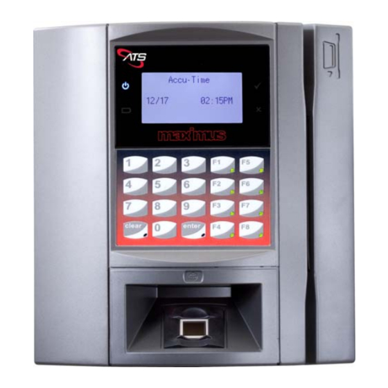
Chapter 1: Terminal Description Maximus Overview Maximus Overview ® The Maximus time and attendance terminal for workforce management features rugged aluminum construction and flexible configuration options. Due to its compact design, Maximus is selected by well-respected companies throughout the world. Founded on a Linux operating system, Maximus has the flexibility to meet a wide array of needs, including Java programmability, Web services, open standards, XML, and a keypad with user defined function keys. - Page 16 Maximus Overview Chapter 1: Terminal Description Figure 1-1 Standard Maximus Terminal (with biometric and “swipe” card readers) Maximus Reference Manual MANU-MAXIMUS-02 Revision-02...
-
Page 17: Specifications
Linux: 32 MB RAM and 32 MB flash XML: 32 MB RAM and 32 MB flash Java: 128 MB RAM and 128 MB flash Programming Java® ATS Universal Command Set (over Linux) or third-party custom application packages Web services enabled Diagnostics On-board diagnostics and remote diagnostic capability Interfaces IEEE 802.3 10/100BASE-T Ethernet with DHCP... - Page 18 Specifications Chapter 1: Terminal Description Maximus Specifications Table 1-1 WiFi Available in two versions: • WPA2/802.11i (enterprise-grade security and authentication protocols) • IEEE 802.11b; 802.11g (Non-Enterprise Version) Optional UPS Discharge life: 1.5 hours at 23°C (73°F) Battery Charging (normal): 0° to 45°C (32° to 113°F) Storage: -20°...
-
Page 19: Part Numbers And Options
Chapter 1: Terminal Description Part Numbers and Options Part Numbers and Options Table 1-2 lists the Maximus terminal main configuration Part Numbers and descriptions. Maximus Part Numbers Table 1-2 Part Number Description Maximus Base Unit MXS2000/XX Base Maximus: • UCS running on Linux OS •... - Page 20 Part Numbers and Options Chapter 1: Terminal Description Maximus Part Numbers Table 1-2 Part Number Description MXS2100/XX Biometric Verification Maximus: • 1:1 E-Field Fingerscan Reader (4K templates - requires PIN) • UCS running on Linux OS • 32MB RAM, 32MB Flash •...
- Page 21 Chapter 1: Terminal Description Part Numbers and Options Maximus Part Numbers Table 1-2 Part Number Description MXS2101/XX Biometric Identification Maximus: • 1:N E-Field Fingerscan Reader (500 templates - no PIN required) • UCS running on Linux OS • 32MB RAM, 32MB Flash •...
- Page 22 Part Numbers and Options Chapter 1: Terminal Description Maximus Part Numbers Table 1-2 Part Number Description MXS2105/XX Cogent Biometric Verification Maximus: • Cogent 1:1 Capacitive fingerscan Reader (9K templates - requires PIN) • UCS running on Linux OS • 32MB RAM, 32MB Flash •...
- Page 23 Chapter 1: Terminal Description Part Numbers and Options Maximus Part Numbers Table 1-2 Part Number Description MXS2106/XX Cogent Biometric Identification Maximus: • Cogent 1:N Capacitive Fingerscan Reader (1200 templates - no PIN required) • UCS running on Linux OS • 32MB RAM, 32MB Flash •...
- Page 24 Part Numbers and Options Chapter 1: Terminal Description Maximus Part Numbers Table 1-2 Part Number Description MXS2107/XX Suprema Biometric Verification Maximus: • Suprema 1:1 Capacitive Fingerscan Reader (9K templates - requires PIN) • UCS running on Linux OS • 32MB RAM, 32MB Flash •...
- Page 25 Chapter 1: Terminal Description Part Numbers and Options Maximus Part Numbers Table 1-2 Part Number Description MXS2108/XX Suprema Biometric Identification Maximus: • Suprema 1:N Capacitive Fingerscan Reader (1200 templates - no PIN required) • UCS running on Linux OS • 32MB RAM, 32MB Flash •...
- Page 26 Part Numbers and Options Chapter 1: Terminal Description Maximus Part Numbers Table 1-2 Part Number Description MXS2111/XX Accu-Touch Biometric Verification Maximus: • Lumidigm 1:1 Multispectral Fingerscan Reader (requires PIN) • UCS running on Linux OS • 32MB RAM, 32MB Flash •...
- Page 27 Chapter 1: Terminal Description Part Numbers and Options Maximus Part Numbers Table 1-2 Part Number Description MXS2112/XX Accu-Touch Biometric Identification Maximus: • Lumidigm 1:N Multispectral Fingerscan Reader (no PIN required) • UCS running on Linux OS • 32MB RAM, 32MB Flash •...
- Page 28 Part Numbers and Options Chapter 1: Terminal Description Table 1-3 lists the Part Numbers for the Maximus modules. Maximus Modules Table 1-3 Part Number Description Internal Readers 97-2111-04 HID Proxpoint 97-2111-03 HID Proxpoint with Biometric Capacitive Fingerscan 1:1 Reader 97-2111-05 HID Proxpoint with Biometric E-Field Fingerscan 1:1 Reader 97-2111-08 HID iClass (Reads card serial number only)
- Page 29 Chapter 1: Terminal Description Part Numbers and Options Maximus Modules Table 1-3 Part Number Description Modem COMM/K56 56K Modem COMM/K67 AirtimeGSM/GPRSCellularFieldUpgradeModemkit (Contact your salesperson for data plans) WiFi Enterprise Version (WPA2/802.11i enterprise-grade security and authentication protocols) Non-Enterprise Version (Wireless Standards: IEEE 802.11b; 802.11g) Battery BATTERY/K14...
- Page 30 Part Numbers and Options Chapter 1: Terminal Description Maximus Accessories Table 1-4 Part Number Description 63-2005-06 Power Injector Cord - Recommended UK Remote Bar Code Readers 9001/03 InfraRed - Weather Resistant - 20' cable 9001/01 Visible Red - Weather Resistant - 20' cable 9001/04 InfraRed - Weather Resistant - 4' cable 9001/02...
-
Page 31: Basic Communication
The acknowledgement (ACK) that is sent by the terminal is also sent by the host. The host application should send an ATS ACK to the terminal in response to all data messages received from the terminal except the following, which are not acknowledged: •... -
Page 32: Dhcp
Basic Communication Chapter 1: Terminal Description DHCP DHCP (Dynamic Host Configuration Protocol) allows a network DHCP server to set the IP addresses automatically for DHCP clients on the network. If a Maximus terminal is connected to a network that has a DHCP server, you can configure the terminal to its IP address from the DHCP server. - Page 33 Installation Chapter About this Chapter This chapter describes the Maximus installation and provides an overview of component and module locations. Chapter Contents This chapter contains the following topics: Installation Guidelines ...................... 2-3 Installation Choices ....................2-3 Wiring Distances ....................2-3 Terminal Wiring Access ..................
-
Page 34: Chapter-2 Installation
Chapter 2: Installation This page intentionally left blank. Maximus Reference Manual MANU-MAXIMUS-02 Revision-02... -
Page 35: Installation Guidelines
Chapter 2: Installation Installation Guidelines Installation Guidelines The standard Maximus is designed to operate indoors. Exposure to outdoor elements, such as rain or snow, voids the manufacturer warranty and may cause damage to the device. Select a location with adequate lighting (away from direct sunlight) and accessibility so employees can operate the terminal safely. - Page 36 Installation Guidelines Chapter 2: Installation Figure 2-1 Power Pack Location Requirements Power Pack within 4-feet (122 cm) of terminal Mount 39 inches (99 cm) from the bottom of the Maximus base to the floor (recommended for ADA requirement) Maximus Reference Manual MANU-MAXIMUS-02 Revision-02...
-
Page 37: Terminal Wiring Access
Chapter 2: Installation Installation Guidelines Terminal Wiring Access The Maximus provides three access points for routing wires into the terminal: two Conduit Openings (holes) and a recessed channel that leads to the “opening to case interior” and accepts surface wiring (see Figure 2-2). -
Page 38: Terminal Installation
Terminal Installation Chapter 2: Installation Terminal Installation This section describes how to wall mount the Maximus terminal and provides the locations of the main components inside. Opening and Separating the Case While not necessary, you may find it easier to install the mounting base on the wall if you separate the base from the terminal. -
Page 39: Mounting The Terminal
Chapter 2: Installation Terminal Installation Figure 2-4 Separating the Terminal from the Base Spring- Loaded Mounting the Terminal When you have run the necessary communication wiring to the terminal location and arranged for a power source, you can mount the terminal on the wall. Choose a flat, smooth, interior wall for the terminal’s location. - Page 40 Terminal Installation Chapter 2: Installation Figure 2-5 Mounting Template Dimensions (Not to Scale) -1/4 in. 0 in. 2 in. 4 in. -6.4 mm 0 mm 50.8 mm 101.6 mm 0 in. 0 mm 1-9/16 in. 40.2 mm 6-5/8 in. 168.3 mm Mount 39 inches (99 cm) from the bottom of the Maximus base to the floor (recommended for ADA requirement) Be sure all required wiring is present and any cable clamps properly installed.
- Page 41 Chapter 2: Installation Terminal Installation Figure 2-6 Installing the Mounting Base (with the terminal separated) Mounting Screws “Started” on the Wall Figure 2-7 Wall Mounting the Maximus (terminal not separated) Mounting Screws “Started” on the Wall MANU-MAXIMUS-02 Maximus Reference Manual Revision-02...
-
Page 42: Main Components
Terminal Installation Chapter 2: Installation If you separated the terminal from the mounting base, reinstall the terminal on the base by reinstalling the terminal’s hinge screws or by sliding the fixed hinge pin into its mating top hole, lifting the lower spring-loaded pin, and pivoting the terminal until the pin drops into its mating hole. - Page 43 Chapter 2: Installation Terminal Installation Figure 2-9 Maximus Component Locations (2) WiFi Module Proximity Reader Board Biometric Reader (Accu-Touch) Main Board Components Figure 2-10 shows the locations of the main components and connectors on the main board. Figure 2-10 Maximus Main Board Connectors Display Power Display Cable Option Board...
-
Page 44: Connections
RJ45 modular plugs on each end. Terminate one end of the cable at the Maximus terminal’s serial option card and the other end at the host computer’s serial port through an ATS RS232 communication adapter. Be sure to follow all applicable electrical codes when installing the cable. -
Page 45: 56K Modem Connection
Chapter 2: Installation Connections Figure 2-12 Connecting an RS232 Serial Module 56k Modem Connection If your Maximus is equipped with a 56k Modem Module, plug one end of a standard RJ11 modular phone cable (customer-supplied) into the socket on the module (as shown in Figure 2-13) and the other end into an analog telephone socket. -
Page 46: Gsm Module
Connections Chapter 2: Installation GSM Module SIM Card Installation If your Maximus is equipped with a GSM (Cellular) Module, install the SIM card (customer- supplied) into the module as shown in Figure 2-14. Figure 2-14 Installing a SIM Card in a GSM Module GSM Long Cable Antenna The optional GSM/GPRS module comes with two antenna. -
Page 47: Dido Relay Module Connection
Chapter 2: Installation Connections Figure 2-15 Installing the 5-Meter Cable Antenna DIDO Relay Module Connection The optional DIDO relay modules enable the terminal to control various external devices such as bells, horns, and doors. The modules provide a relay contact closure to activate electronic access entry, solenoids or buzzers. - Page 48 Connections Chapter 2: Installation Solid State DIDO Modules The DO functionality of the modules utilize either a 120 VAC / 2 amp, a 240 VAC / 1 amp, or a 60 VDC, 3 amp solid state relay. A five-position screw down connector serves as the gateway between the Relay Module peripheral controller and the external mechanism.
- Page 49 Chapter 2: Installation Connections Connecting the Module The DIDO modules come equipped with Phoenix Contact PCB terminal block(s) to connect wiring to the DIDO module. You may disconnect the terminal block(s) from the module then connect the wiring for the appropriate module as described in the previous section. Plug the terminal block back into the module as shown in Figure 2-19 (single module) or...
-
Page 50: Hand-Held Ccd Scanner
Connections Chapter 2: Installation Hand-Held CCD Scanner If you have an optional ATS hand-held CCD scanner (Part Number 9000/39), plug its cable into the Wand Socket on the Maximus Main Board as shown in Figure 2-21. Figure 2-21 Connecting a Hand-Held CCD Scanner WiFi External Antenna The optional WiFi module comes with two antenna. -
Page 51: Power Connection
When using a power pack, terminal power is supplied by plugging the output cable from an ATS 12VDC power pack directly into the DC Power connector on the back of the terminal. Ensure that a conventional 120VAC wall outlet (220VAC in Europe and other areas, check local electrical code requirements) is available to accept the power pack. -
Page 52: Connecting The Ups Battery
Maximus terminals can be equipped with an optional UPS battery system that supplies power to the terminal in the event of an electrical power outage. ATS disconnects the UPS battery pack prior to shipping to prevent the battery pack from discharging in case of extended storage periods. - Page 53 Chapter 2: Installation Power Connection Figure 2-25 Connecting the Battery Pack The charger board has an LED, D3. The LED has three states: blinking, lit steadily on, and off. • Blinking – Indicates the battery is being fast charged. It takes about seven hours to completely charge a fully drained battery.
- Page 54 Power Connection Chapter 2: Installation This page intentionally left blank. 2-22 Maximus Reference Manual MANU-MAXIMUS-02 Revision-02...
- Page 55 Power Up ........................3-4 Initial Setup ........................3-5 Initial Setup Menu Navigation ................3-5 Initial Setup Parameters ..................3-7 ATS TSD Mode ....................... 3-13 Using the TSD Mode ................... 3-14 ATS Setup Mode ......................3-15 Setup Mode Parameters ..................3-16 Re-Boot ......................
- Page 56 Chapter 3: Monochrome Terminals Date/Time Setup ......................3-39 Information Mode ......................3-41 Version Info ......................3-42 Memory Info ....................... 3-43 Misc Info ......................3-44 Ethernet Info ....................... 3-44 Information Mode ......................3-41 Test Mode ........................3-46 Accessing Test Mode ................... 3-46 Reader Test ......................
-
Page 57: Chapter-3 Monochrome Terminals
Chapter 3: Monochrome Terminals Monochrome Display Monochrome Display While the power and physical characteristics of a monochrome and color Maximus are the same, their setup menus are different. You can differentiate between the monochrome and color Maximus without turning on the terminal. The monochrome Maximus lens has a much smaller window/LCD display than the color lens. -
Page 58: Power Up
Power Up Chapter 3: Monochrome Terminals Power Up If the terminal does not have an application saved the message Download Needed appears at power-up or after a re-boot showing that the terminal is ready to accept (needs) a program download from the host. Download Needed PGM: nnnn-nnn-nnn The numeric value after the Program prompt (PGM:), nnnn-nnn-nnn, shows the terminal... -
Page 59: Initial Setup
Chapter 3: Monochrome Terminals Initial Setup Initial Setup To enter configuration mode, press and hold both the clear and enter keys simultaneously for about five seconds. If the terminal prompts you to enter a password, type in the password using the numeric keys then press the enter key. The Initial Setup parameters appear starting with Setup Host IP. - Page 60 Setup the SubMask 255.255.255.000 enter DHCP Option Code enter Terminal Name: ATS000001 enter Append TCP Data with ATS TSD Mode EOT: No Setup Mode enter enter ATS Setup Mode ATS Setup Mode Re-Boot Setup Password clear Maximus Reference Manual...
-
Page 61: Initial Setup Parameters
Chapter 3: Monochrome Terminals Initial Setup Initial Setup Parameters To enter the initial setup menu press the clear and enter keys simultaneously for 5-seconds (maximum). Enter a password if prompted. The terminal displays the default (192.168.001.100) or saved value for the Host that provides communications to the terminal. - Page 62 If the terminal was already in the displayed mode (Dynamic DHCP or Static IP) and you pressed the enter key without changing it, the terminal enters the Mode. Proceed to "ATS TSD Mode" on page 3-13). • The Static IP selection enables you to set the terminal to a permanent IP address.
- Page 63 Chapter 3: Monochrome Terminals Initial Setup Next the terminal displays the Setup Router IP (Gateway IP address) parameter. Press the enter key to accept the displayed address or press the clear key then use the numeric keys to change the address. Press the enter key to save the new Gateway IP address when finished.
- Page 64 Initial Setup Chapter 3: Monochrome Terminals After saving the DNS server IP address the terminal displays the Setup the Submask parameter (the default subnet mask value is 255.255.255.000). Setup the SubMask 255.255.255.000 Press the enter key to accept the displayed subnet mask value and continue or press the clear key then use the numeric keys to change the value.
- Page 65 Next the terminal displays the Terminal Name parameter that enables you to set a unique up-to-20 character administrative name for the terminal. The default name is “ATS” plus the last 6-digits of the terminal MAC address (e.g., ATS000001). Terminal Name: ATS000001 Applications such as Accu-Engine require “ATS”...
- Page 66 Initial Setup Chapter 3: Monochrome Terminals 10. Next the terminal displays the Append TCP Data with EOT parameter (the default is No). Append TCP Data with EOT: No Press the enter key to accept the displayed selection (Yes or No) or press the clear key to toggle between Yes and No for support of end-of-transmission (EOT) data.
-
Page 67: Ats Tsd Mode
You can enable password protection so only authorized persons can enter TSD mode. See NOTE: "Setup Password" on page 3-17 for details. Figure 3-3 provides a flow chart of the ATS TSD Mode menu navigation. Figure 3-3 ATS TSD Mode Navigation Flow Chart Setup Host IP nnn.nnn.nnn.nnn... -
Page 68: Using The Tsd Mode
ATS TSD Mode Chapter 3: Monochrome Terminals Using the TSD Mode Once in the ATS TSD Mode menu you can navigate and make selections as follows: • Press the clear key to cycle through the ATS TSD Mode menu items. -
Page 69: Ats Setup Mode
Chapter 3: Monochrome Terminals ATS Setup Mode ATS Setup Mode The ATS Setup Mode enables you to setup connected/installed devices, a password, and manage downloads. Figure 3-4 provides a flow chart of the ATS Setup Mode menu items. Figure 3-4... -
Page 70: Setup Mode Parameters
ATS Setup Mode Chapter 3: Monochrome Terminals Setup Mode Parameters Setup Mode provides the following parameters: • "Re-Boot" on page 3-16 • "Setup Password" on page 3-17 • "Setup Host Connect" on page 3-18 • "Setup Smartcard" on page 3-27 •... -
Page 71: Setup Password
Chapter 3: Monochrome Terminals ATS Setup Mode If you pressed the enter key at the Re-Boot prompt the terminal prompts you to confirm the re-boot. Press the enter key to confirm and re-boot the terminal or press the clear key to return to the Re-Boot prompt. -
Page 72: Setup Host Connect
ATS Setup Mode Chapter 3: Monochrome Terminals The terminal now displays the Confirm Password prompt. Re-type the password from the previous step then press the enter key. Confirm Password The terminal displays the Re-Boot prompt. Press the enter key to confirm and re-boot the terminal. - Page 73 Chapter 3: Monochrome Terminals ATS Setup Mode If you pressed the enter key the terminal displays the current host type setting (either Ethernet and Serial). Press the enter key to accept (select) the displayed setting or press the clear key to change it (select the other option).
- Page 74 Press the enter key when the terminal displays the desired provider. The available providers are; stream, proximus, o2, etisalat, datalink, att-gold, att, ats-tm, O2UK, ATS-t-mobil, Wlogic-ATT, wlogic, AIS, vodafoneUK, vodafone, vodacom, vodaPAYG, telenor, t-mobil-uk, t- mobile.
- Page 75 Port. and returns you to the saved/default value. Press the clear key again to correct the port number then press the enter key to save it. By default, ATS uses port 2500 for the network connection between the terminal and a connecting computer.
- Page 76 You can access the following parameters by pressing the clear key, toggling the Static IP and Dynamic DHCP selections and re-saving Static IP. ATS supports Internet Protocol version 4 (IPv4) addressing. If you type an invalid IP, subnet NOTE: mask, or other value, the terminal tells you the error and prompts you to retry using a valid entry.
- Page 77 Chapter 3: Monochrome Terminals ATS Setup Mode 10. Next the terminal displays the Setup Router IP (Gateway IP address) parameter. Press the enter key to accept the displayed address or press the clear key then use the numeric keys to change the address. Press the enter key to save the new Gateway IP address when finished.
- Page 78 ATS Setup Mode Chapter 3: Monochrome Terminals 12. After saving the DNS server IP address the terminal displays the Setup the Submask parameter (the default subnet mask value is 255.255.255.000). Setup the SubMask 255.255.255.000 Press the enter key to accept the displayed subnet mask value and continue or press the clear key then use the numeric keys to change the value.
- Page 79 14. Next the terminal displays the Terminal Name parameter that enables you to set a unique up-to-20 character administrative name for the terminal. The default name is “ATS” plus the terminal serial number (e.g., ATS000001). Terminal Name: At this time the terminal does not save any changes to the Terminal Name. If you make any NOTE: changes the terminal reverts to the default Terminal Name after a re-boot.
- Page 80 ATS Setup Mode Chapter 3: Monochrome Terminals If you selected Serial for the Host Type If you selected Serial for the Host Type the terminal prompts you to enter the terminal (clock) address (Enter Clock Address). Press the enter key to accept the displayed value or press the clear key then use the numeric keys to change it.
-
Page 81: Setup Smartcard
1 Ring, 2 Rings, or 3 Rings. Press the enter key to accept (set) the displayed value and continue or press the clear key to change the setting. When you are finished press the enter key and the terminal returns to the Setup Password prompt (start of the ATS Setup Menu). Set Auto Answer None... -
Page 82: Setup Comm Port
ATS Setup Mode Chapter 3: Monochrome Terminals Setup Comm Port Set the communication port connection for terminals that use a serial connection. These settings must match the communication software and hardware you are using to connect to the terminal. When the terminal displays the Setup Comm Port menu (typically after the... -
Page 83: Device Setup
Chapter 3: Monochrome Terminals ATS Setup Mode Next the terminal displays the Parity bit parameter. Press the enter key to accept/set the displayed value or press the clear key to scroll between the O (Odd), E (Even), and N (None) options. When finished press the enter key to save the setting and proceed to the next menu item. - Page 84 ATS Setup Mode Chapter 3: Monochrome Terminals In the Device Type parameter menu, press the clear key to scroll between Device None, Finger Geometry, FPR Lumidigm Verify, FPR Suprema Verify, FPR Bioscrypt, FPR Cogent Verify, FPR Lumidigm ID, FPR Suprema ID, and FPR Cogent ID options.
-
Page 85: Setup Wifi
Chapter 3: Monochrome Terminals ATS Setup Mode ATS Setup Mode Setup WiFi When you enter the Setup WiFi menu the terminal displays the WiFi version. When ready press the clear or enter key to proceed. WiFi Signal Version= X.X.X.XXX If the WiFi unit is not installed or functioning the terminal displays the No WiFi message:... - Page 86 Exit WiFi Setup prompt. Press the clear key to proceed to the next item in the Setup Wifi menu or press the enter key to exit the WiFi.setup menu and return to the ATS Setup Mode menu. WiFi Signal...
- Page 87 If you pressed the enter key the terminal prompts you to exit. Press the enter key to exit the WiFi.setup menu and return to the ATS Setup Mode menu or press the clear key to proceed to the next WiFi menu item.
- Page 88 ATS Setup Mode Chapter 3: Monochrome Terminals If you pressed the clear key at the Exit WiFi Setup prompt the terminal displays the Set Security Key prompt (WiFi network password). WiFi Signal Set Security Key Press the clear key to proceed to the next menu item without setting a security key or press the enter key to set a key.
- Page 89 The terminal returns to the start of the Setup WiFi menu. Set SSID _______ATS_WIFI_KIT Press the clear key repeatedly until the terminal displays the Exit WiFi Setup prompt. Press the enter key to exit and return to the ATS Setup Mode. WiFi Signal Exit WiFi Setup Delete FP Templates...
-
Page 90: Delete Fp Templates
ATS Setup Mode Chapter 3: Monochrome Terminals The Delete FP Templates command, added in Firmware 2.05.08(X), gives you the ability to erase all saved biometric templates via the terminal Setup Menu. This command only appears if your terminal is equipped with a FPR biometric device (“Finger Print Reader”). -
Page 91: Reset Dnld
"Power Up" on page 3-4). Use the following procedure to clear the terminal memory (reset the download): Press the clear key repeatedly in the ATS Setup Mode menu until the terminal displays the Reset Dnld (XXXXXXXX) prompt. ATS Setup Mode... -
Page 92: Download From Usb
ATS Setup Mode Chapter 3: Monochrome Terminals Download from USB The Download from USB command enables you to install downloads (applications) to the Maximus terminal from a USB flash drive. With a USB flash drive that contains the (*.dld) download file(s) installed in the Maximus USB port, press the enter key to access the... -
Page 93: Download From Usb
Use the following procedure to change the terminal Date and Time: Go to the ATS TSD Mode and press the clear key until the Date/Time Setup prompt appears then press the enter key to access the Date/Time menu. ATS TSD Mode... - Page 94 (you can use the clear key to delete the last number you entered). When you are finished press the enter key save the time and to return to the start of the ATS TSD Mode menu. Set Time HH:MM...
-
Page 95: Information Mode
Information Mode enables you to view the terminal firmware version, memory size, hardware component versions, serial number, and Ethernet configuration settings. You access the Information Mode from ATS TSD Mode. See "ATS TSD Mode" on page 3-13 for information on accessing the ATS TSD Mode. -
Page 96: Version Info
Information Mode Chapter 3: Monochrome Terminals Version Info Version Info enables you to view the version and date of firmware and hardware installed on the terminal. Use the following procedure to view the version information: Enter the Information Mode menu then press the enter key when the Version Info menu prompt appears. -
Page 97: Memory Info
Information Mode Exit Press the enter key to exit from the Information Mode menu and return to the ATS TSD Mode menu or press the clear key to proceed to the Memory Info prompt. Memory Info Memory Info enables you to view the amount of RAM and Flash memory installed on the terminal and the amount currently used. -
Page 98: Misc Info
Use the “F7” and “F8” keys to scroll through the following information: • Serial Number (the terminal serial number) • Customer Number (customer number as noted at the ATS factory) • G-10 Number (PC board assembly number) • CPU (terminal CPU type and version) When finished, press the enter or clear key to return to the Information Mode menu then press the clear key to proceed to the Ethernet Info prompt. -
Page 99: Ethernet Info
Chapter 3: Monochrome Terminals Information Mode Press the clear key when in the Information Mode menu until the Ethernet Info prompt appears then press the enter key. Information Mode Ethernet Info Host IP: XXX.XXX.XXX.XXX Use the “F7” and “F8” keys to scroll through the following information: •... -
Page 100: Test Mode
You can access Test Mode from the ATS TSD Mode menu. See "ATS TSD Mode" on page 3- for how to access the ATS TSD Mode menu. When in the ATS TSD Mode, press the clear key until the Test Mode menu option appears then press the enter key. Figure 3-8 provides a flow chart of the Test Mode menu navigation. -
Page 101: Reader Test
Test Mode menu (at the Test Mode, Exit prompt). Exit Selecting Exit from the Test Mode menu returns you to the ATS TSD Mode menu. Use the following procedure to access the Exit command: In the Test Mode menu, press the clear key until the Exit option appears. -
Page 102: System Diag Dump
Chapter 3: Monochrome Terminals Test Mode Exit Press the enter key to exit test mode and return to start of the ATS TSD Mode menu (Setup Mode option), or press the clear key to proceed to the System Diag Dump option. -
Page 103: Smart Card Test
Chapter 3: Monochrome Terminals Test Mode The terminal displays the Results copied to USB message when the text file has been copied to the USB flash drive. You may now remove the USB flash drive then open the text file on a personal computer. Results copied to When finished press the clear key to exit the System Diag Dump and return to the Test Mode menu (at the Smart Card Test option). -
Page 104: Serial Test: Direct
(Serial Test: Direct). Serial Test: Direct This test requires specific loopback “jumper” and is typically only performed by an ATS service technician. It is noted here for reference purposes. Install the “jumper” in the serial port on the terminal. -
Page 105: Serial Test: Printer
Chapter 3: Monochrome Terminals Test Mode Serial Test: Printer This test requires specific loopback “jumper” and is typically only performed by an ATS service technician. It is noted here for reference purposes. Install the “jumper” in the serial /printer port on the terminal. -
Page 106: Display Test
Test Mode Chapter 3: Monochrome Terminals Press the enter key to initiate the test. The terminal illuminates all the LEDs on the terminal then briefly shuts them all off. When the test is complete the “power LED” returns to the normal illuminated state (and any others if applicable). -
Page 107: System Test
Chapter 3: Monochrome Terminals Test Mode System Test The system test performs a quick check on the integrity of the RAM, FLASH, and EEPROM installed on the terminal. Use the following procedure to initiate a system test: In the Test Mode menu, press the clear key until the System Test option appears. -
Page 108: Usb Test
Test Mode Chapter 3: Monochrome Terminals USB Test The USB test checks the functionality of the USB on the terminal. This test requires a USB flash drive. Use the following procedure to perform the USB test: In the Test Mode menu, press the clear key until the USB Test option appears. Test Mode USB Test Press the enter key to start the test. - Page 109 Chapter 3: Monochrome Terminals Test Mode Press the enter key to select the Battery/Charger Test option. Battery/Charger Test Press Enter to Test Press the enter key to start the test. The system checks that the terminal is equipped with a UPS battery backup system and displays the result. Battery/Charger Test UPS Present Press the enter key to test the condition of the battery.
-
Page 110: Modem Test
Test Mode Chapter 3: Monochrome Terminals Press the enter key to return to beginning of the Battery/Charger Test. Battery/Charger Test Press Enter to Test When you are finished press the clear key to exit the battery/charger test and return to the Test Mode menu (at the Modem Test option). Modem Test The modem test checks the functionality of an optional modem (if installed in the terminal). -
Page 111: Rtc Test
Chapter 3: Monochrome Terminals Test Mode RTC Test The RTC test checks the functionality of the Real Time Clock and beeps every second while flashing the “OK” LED during the test. Use the following procedure to run the RTC test: In the Test Mode menu, press the clear key until the RTC Test option appears. -
Page 112: Gsm Signal Strength
The DIDO test checks the functionality of the Data-In-Data-Out port on the terminal (also referred to as the Auxiliary Port). This test requires specific loopback “jumper” and is typically only performed by an ATS service technician. It’s noted here for reference purposes. Insert the “loopback jumper” into the DIDO port on the terminal. -
Page 113: Keypad Test
Chapter 3: Monochrome Terminals Test Mode Press the enter key to start the test. The terminal displays the result when the test is complete. Test DIDO 1 Test in progress When you are finished, press the clear key to exit and return to the start of the DIDO test. -
Page 114: Biometric Test
Test Mode Chapter 3: Monochrome Terminals Press the numeric keys in sequence from 1 to 9 then the 0 key. Next press the function keys in order (i.e., “F1” then “F2” and so forth to “F8”). If you press a button out of sequence, the terminal sounds an error tone and the “X / Error”... - Page 115 Chapter 3: Monochrome Terminals Test Mode Press the enter key to select the Biometric Test option. The terminal displays the Test Finger Print prompt. Test Finger Print Press Enter to start Press the enter key to start the test. The system prompts you to place your finger on the reader.
- Page 116 Test Mode Chapter 3: Monochrome Terminals This page intentionally left blank. 3-62 Maximus Reference Manual MANU-MAXIMUS-02 Revision-02...
- Page 117 Color Terminals Chapter About this Chapter This section tells you how to use the color Maximus menus to set up your color terminal. (See Chapter 3, "Monochrome Terminals" to set up a monochrome Maximus.) If you have a Accu-Engine Serial terminal configured for Java programming, see the NOTE: Advanced Development Manual for Accu-Time Terminals for additional information.
-
Page 118: Chapter-4 Color Terminals
Chapter 4: Color Terminals This page intentionally left blank. Maximus Reference Manual MANU-MAXIMUS-02 Revision-02... -
Page 119: Color Display
Chapter 4: Color Terminals Color Display Color Display While the power and physical characteristics of a monochrome and color Maximus are the same, their setup menus are different. You can differentiate between the monochrome and color Maximus without turning on the terminal by looking at the lens. The color Maximus lens has a much larger window/LCD display than the monochrome lens. -
Page 120: Using The Configuration Menu
Using the Configuration Menu Chapter 4: Color Terminals Using the Configuration Menu The configuration menu lets you access some frequently used terminal functions. Figure 4-2 shows which function key corresponds to which menu selection. The text on your keypad might not be the same as shown in Figure 4-2 (e.g., “In”... - Page 121 Chapter 4: Color Terminals Using the Configuration Menu Figure 4-3 Color Maximus Configuration Menu (Initial Setup Menu Shown) Host 03:12:18 Date & Address Time Friday Reset Nov 7, 2014 Download Static & FP Host XXX.XXX.XXX.XXX Device Clk XXX.XXX.XXX.XXX Rtr XXX.XXX.XXX.XXX Test, Mask XXX.XXX.XXX.XXX Setup,...
-
Page 122: Initial Setup
Initial Setup Chapter 4: Color Terminals Initial Setup The Initial Setup Menu, shown in Figure 4-3 on page 4-5, enables you to configure the basic parameters to quickly connect your Maximus to its host/network and to access other menus. Simultaneously press and hold down the clear and enter keys for about five seconds (and enter the password if prompted for it) to launch the Initial Setup menu. - Page 123 Chapter 4: Color Terminals Initial Setup Static IP / Dynamic DHCP This parameter enables you to switch the IP mode of the Maximus terminal. When set to Static IP, the IP address of the terminal is fixed. Use the IP Address parameter to set a static IP address for the terminal (described in the following section).
- Page 124 Initial Setup Chapter 4: Color Terminals Figure 4-6 Reboot Confirmation Window 03:38:15 Friday Nov 7, 2014 You have asked for a re-boot or have changes that require re-boot Return re-start Setup The Reboot Confirmation window provides two options: • Press the “F4” key to select OK Re-start. Selecting this option reboots the terminal and applies any changes you have made.
- Page 125 Chapter 4: Color Terminals Initial Setup Set Date & Time The Set Date & Time parameter enables you to manually set the current date, current time, and the date format used by the terminal. Press the “F5” key to access the Set Date & Time options screen as shown in Figure 4-7.
- Page 126 Initial Setup Chapter 4: Color Terminals Figure 4-8 Enter Date Prompt Screen 09:08:21 Thursday Nov 13, 2014 Enter the new date in the form XX/XX/XX Enter Date • Set Time – Press the “F2” key to display the Enter Time prompt screen as shown in Figure 4-9.
- Page 127 Chapter 4: Color Terminals Initial Setup • DateFormat For Setup– Press the “F3” key to cycle through MMDDYY, DDMMYY, or YYMMDD for the date format. The selected format displays in real time on the option field. • Return To Setup – Press the “F4” key to exit the Set Date & Time and Initial Setup menus and go directly to Setup Mode.
- Page 128 Initial Setup Chapter 4: Color Terminals • Confirm Reset Download - Press the “F2” key to reboot the Maximus terminal and clear the terminal memory, including all prompts and data in any queues. After you reset the download, you need to download parameters to the terminal to make it functional.
-
Page 129: Test, Setup, Diagnostics (Tsd) Menu
Chapter 4: Color Terminals Test, Setup, Diagnostics (TSD) Menu Test, Setup, Diagnostics (TSD) Menu The Test, Setup, Diagnostics menu enables you to access Test Mode, Setup Mode, Information Mode, the Restore Factory Settings command, and Download from USB command. Press the “F7” key, when in the Initial Setup Menu screen (shown in Figure 4-3 on page 4-5), to open the Test, Setup, Diagnostics screen as shown in... - Page 130 Test, Setup, Diagnostics (TSD) Menu Chapter 4: Color Terminals Download from USB – The Download from USB command (“F4” key) enables you to install downloads (applications) to the Maximus terminal from a USB flash drive. With a USB flash drive that contains download files (*.dld) installed in the Maximus USB port, press the “F4”...
-
Page 131: Host Type
Chapter 4: Color Terminals Setup Mode Setup Mode Use setup mode to configure the terminal, including setting serial or Ethernet host and parameters. To enter setup mode, press the”F1” key to select Setup Mode when in the Test, Setup, And Diagnostics screen (see "Test Setup Diagnostics"... -
Page 132: Common Settings
Setup Mode Chapter 4: Color Terminals Figure 4-15 Setup Mode, Main Menu Screen – Host Type Ethernet Host Device 03:38:15 Type None Ethernet Friday Setup Nov 7, 2014 TCP/IP Password WiFi Setup MAC XXXX:XXXX:XXXX:XXXX Host XXX.XXX.XXX.XXX Comm Clk XXXXXX Port Exit Setup Common Settings... - Page 133 If you set a password, be sure to record the value in a safe place. If you lose the password, NOTE: you cannot change the terminal setup. (If you encounter this problem, contact ATS for recovery assistance.) Use the following procedure to set a password: Press the “F6”key to select Set Password.
-
Page 134: Serial Setup
Setup Mode Chapter 4: Color Terminals At the Enter New Password prompt press the Enter key without typing any numbers. At the Confirm Password prompt press the Enter key without typing any numbers. Press the “F8” key to select Exit Setup then press the “F4” key to select OK Re-Start to reboot the terminal. - Page 135 Chapter 4: Color Terminals Setup Mode Figure 4-16 Serial Setup Menu Screen 03:44:53 Clock Address Friday Nov 7, 2014 Country Code Setup Clock Address XX Country Code XX Auto Auto Answer X Answer Direct Return Modem Setup If the Maximus connects to a serial modem, press the “F1” key to select Clock Address.
- Page 136 Setup Mode Chapter 4: Color Terminals Figure 4-17 Select Device Type Screen (Shown with Modem Option Selected) 09:39 AM Thursday Nov 13, 2014 Select Device Type Modem Next If the Maximus connects to a serial modem, press the”F2” key to select appropriate Country Code for your modem (e.g., the T.35/D1/J1 country code for the United States is B5 while the S1 code is 22).
- Page 137 Chapter 4: Color Terminals Setup Mode Figure 4-18 Comm Port Menu Screen 03:42:04 Smartcard Baud Rate Friday Nov 7, 2014 Data Bits Baud Rate XXXXXX Data Bits XX Parity XXX Stop Bits X Parity Return Stop Bits Setup Use the following procedure to configure the serial communications settings: To change the Baud Rate press the “F1”...
-
Page 138: Ethernet Setup
Setup Mode Chapter 4: Color Terminals Ethernet Setup The Setup TCP/IP WiFi and associated sub-menus enable you to customize the Ethernet and WiFi settings for a Maximus connected to the host via an Ethernet interface. Figure 4-19 Ethernet Setup Screen – Ethernet Host Type Host Device 03:38:15... - Page 139 To change the GSM / GPRS provider press the “F2” key to cycle through the provider options. The available providers are; stream, proximus, o2, etisalat, datalink, att-gold, att, ats-tm, O2UK, ATS-t-mobil, Wlogic-ATT, wlogic, AIS, vodafoneUK, vodafone, vodacom, vodaPAYG, telenor, t-mobil-uk, t- mobile.
- Page 140 Setup Mode Chapter 4: Color Terminals In addition, the GSM PPP Setup screen displays the GSM/GPRS Host IP address in the center of the screen (the IP address of a public-facing server that communicates with the terminal using the wireless data network). To change this IP address, press the “F3”...
- Page 141 Chapter 4: Color Terminals Setup Mode The center of the screen displays the Set Type of Security prompt. Press the enter key to set the security protocol type. Select Next (“F8” key) or use the clear key to scroll between the WPA2, WPA, WEP, and None options. When the terminal displays the desired option, press the enter key to set the encryption type.
- Page 142 Setup Mode Chapter 4: Color Terminals Figure 4-21 TCP/IP Setup – Dynamic Mode 03:38:15 TCP/IP Socket Client Port Friday Append Nov 7, 2014 Dynamic DHCP Socket Port XXXX DHCP OptionCode XXX Clk XXXXXXXXX DHCP WiFi XXXXXXX Option Disabled Code Return Setup WiFi Setup...
- Page 143 Chapter 4: Color Terminals Setup Mode Figure 4-22 TCP/IP Setup – Static Mode 03:38:15 TCP/IP Socket Client Port Friday Nov 7, 2014 Append Static Socket Port XXXX DHCP OptionCode XXX Clk XXXXXXXXX WiFi Enabled Disabled Addresses Return Setup WiFi Setup Use the following procedure to configure the Static Mode Ethernet settings: Press the “F3”...
- Page 144 Setup Mode Chapter 4: Color Terminals Figure 4-23 Secondary TCP/IP Setup Screen, Static Mode Host 03:38:15 Address Address SubMask Friday Clock Nov 7, 2014 Terminal Name Address Host XXX.XXX.XXX.XXX Clk XXX:XXX:XXX:XXX Rtr XXX.XXX.XXX.XXX Router DNS XXX.XXX.XXX.XXX Server Address Return Exit Setup TCP/IP Use the following procedure to change the Static IP settings (if desired):...
- Page 145 The default name is “ATS” plus the last 6-digits of the terminal MAC address (e.g., ATS000001). Applications such as Accu-Engine require “ATS” as the first three characters of the Terminal NOTE: Name. If not, Accu-Engine will only display the terminal IP address (that can change with DHCP enabled).
-
Page 146: Test Mode
Test Mode Chapter 4: Color Terminals Test Mode To enter Test Mode, press the “F7” key to select Test, Setup, Diagnostics from the main Configuration Menu screen (shown in Figure 4-24) and enter the Test, Setup Diagnostics menu screen as shown in Figure 4-25. - Page 147 Chapter 4: Color Terminals Test Mode Press the “F2”Function key to enter Test Mode and display the Test Mode screen as shown in Figure 4-26. Figure 4-26 Test Mode 03:38:15 Friday Nov 7, 2014 Test Mode Test Name Prev Next To exit Test Mode, cycle through the test selections until the Exit option appears, then press NOTE: the enter key.
- Page 148 Test Mode Chapter 4: Color Terminals Keypad Test This tests each numeric and function key on the terminal. If you press an incorrect key the system will beep and the red LED (X) flashes. When you successfully complete the test the system exits to the next test.
- Page 149 Chapter 4: Color Terminals Test Mode System Test This does a quick check on the integrity of the RAM, FLASH, and EEPROM installed on the terminal. Press the enter key when the display reads “Test Mode System Test” to enter the test and display the “System Test Press Enter to Test”...
-
Page 150: Information Mode
Information Mode Chapter 4: Color Terminals Information Mode To enter Information Mode, select Information Mode (“F3” key) from the Test, Setup, Diagnostics menu (see "Test, Setup, Diagnostics (TSD) Menu" on page 4-13). To navigate Information Mode: • Use the Next function (“F8” key) to cycle through the tests. •... - Page 151 Misc Info – press ENTER to view the following miscellaneous information: • Serial Number (the terminal serial number) • Customer Number (customer number as noted at the ATS factory) • G-10 Number (PC board assembly number) • CPU (terminal CPU type and version) •...
-
Page 152: Setting Up The Screensaver
Setting Up the Screensaver Chapter 4: Color Terminals Setting Up the Screensaver The Color Maximus terminal features an automatic screen saver that is disabled by default. The screen saver is designed to protect the terminal screen from burn-in during periods of inactivity. - Page 153 Maintenance Chapter About this Chapter This section tells you about power, maintenance, and troubleshooting for your Maximus terminal. If you have a Accu-Engine Serial terminal configured for Java programming, see the NOTE: Advanced Development Manual for Accu-Time Terminals for additional information. Chapter Contents This chapter contains the following topics: Verifying Installation ......................
-
Page 154: Chapter-5 Maintenance
Chapter 5: Maintenance This page intentionally left blank. Maximus Reference Manual MANU-MAXIMUS-02 Revision-02... -
Page 155: Verifying Installation
Maximus terminal and its host. Accu-Time Systems, Inc., has two sample host applications available: Accu-Engine and Accu- Engineer. Your ATS representative can provide a copy. Use these to send a program download file to a terminal and monitor the terminal’s response. -
Page 156: Maintenance
Low-usage readers should be cleaned monthly. High-usage readers should be cleaned weekly. Although the finger sensors used in ATS terminals have few maintenance and handling requirements, a few basic precautions help ensure a high level of performance over the life of the sensor. -
Page 157: Cleaning The Biometric Sensor
Chapter 5: Maintenance Maintenance Cleaning the Biometric Sensor Use the following procedure to clean the Biometric sensor surface (all sensor technologies): Remove electrical power from the finger sensor by disconnecting the terminal from its power source. Use an alcohol prep wipe or dampen (not soaking or dripping wet) a clean cotton swab, a clean cotton ball, or a non-abrasive cloth with isopropyl alcohol. - Page 158 Maintenance Chapter 5: Maintenance Cleaning an E-Field Conductive Ring (Bioscrypt) After an extended period of use, the conductive ring, surrounding the sensor, may become tarnished or accumulate deposits that can degrade performance (see "E-Field Sensor (Bioscrypt)" on page A-9 for how the conductive ring operates with the sensor). Figure-6 Bioscrypt E-Field Sensor Conductive Ring Conductive Ring...
-
Page 159: Caring For The Biometric Sensor
Chapter 5: Maintenance Maintenance Caring for the Biometric Sensor The sensor is designed to perform well even under harsh conditions. Nevertheless, some precautions should be taken to avoid damaging the sensor: • Do not place the finger sensor close to a heat source, such as a radiator or hot plate. -
Page 160: Troubleshooting Guide
Troubleshooting Guide Chapter 5: Maintenance Troubleshooting Guide The terminal has no user-serviceable parts. Accu-Time terminals must be operated within the parameters described in this document. Any operation performed contrary to these CAUTION parameters voids the warranty. Troubleshooting Diagnostic Table Table 6-1 Symptom Possible Cause Solution... - Page 161 Chapter 5: Maintenance Troubleshooting Guide Troubleshooting Diagnostic Table Table 6-1 Symptom Possible Cause Solution Terminal does not Keyed data does not exist in See a supervisor accept keypad input. validation file Keypad connector is Test the keypad in Test Mode (for monochrome unplugged.
-
Page 162: Power-Related Troubleshooting
Troubleshooting Guide Chapter 5: Maintenance Power-Related Troubleshooting Table 6-2 Symptom Possible Cause Solution The terminal display is blank. The primary of the power pack Check the outlet, both power pack assembly is not plugged into an AC- connections, and that it is a 12 VDC wall outlet, is not plugged into the power pack. - Page 163 Solution The terminal is Communication Use Setup Mode to setup the terminal (for monochrome parameters were not terminals, see "ATS Setup Mode" on page 3-15, and for color communicating previously set. terminals, see "Setup Mode" on page 4-15). Your network with the host.
- Page 164 Troubleshooting Guide Chapter 5: Maintenance This page intentionally left blank. 5-12 Maximus Reference Manual MANU-MAXIMUS-02 Revision-02...
- Page 165 This Appendix contains the following topics: Why Use Biometrics? ....................... A-3 User Confidentiality ....................A-3 Reliability Rules ..................... A-3 ATS Biometric Operational Options ............... A-4 Verification and Identification Modes ................A-5 Verification Mode ....................A-5 Identification Mode ....................A-5 How it Works ........................A-6 Recommended Fingers ..................
-
Page 166: Appendix-A Biometrics
Appendix A: Biometrics This page intentionally left blank. Maximus Reference Manual MANU-MAXIMUS-02 Revision-02... -
Page 167: Why Use Biometrics
Biometric devices are susceptible to vandalism. • Environmental conditions can affect operation (e.g., moisture, dust, cold). ATS uses these fingerscan technologies for their proven reliability given a few simple rules: All terminals within a facility are installed correctly (installation height observed, obstructions avoided). -
Page 168: Ats Biometric Operational Options
This may be necessary if the reader cannot obtain a “good fingerscan” due to physiological issues. • Adjust False Acceptance Rate - ATS terminals enable you to set the threshold for fingerscan matching accuracy. Maximus Reference Manual... -
Page 169: Verification And Identification Modes
There are no actual “fingerprints” stored anywhere, merely an arithmetic representation of certain minutiae points. ATS biometric devices have two modes of operation: • 1:1 Mode (one-to-one mode) or Verification Mode •... -
Page 170: How It Works
How it Works Appendix A: Biometrics How it Works At enrollment, the biometric reader scans the user’s fingerprint and creates a numeric data template from the fingerprint image. Once it creates the template it discards the fingerprint image/scan. Templates are used for comparison to live fingerscans and are either stored at the terminal or on a host. -
Page 171: Recommended Fingers
Appendix A: Biometrics How it Works Figure A-2 Identifying Points Within Image “Y” Split End-Point Most biometric units only look at the skin surface. These readers are more susceptible to misreads caused by damage on the top layer of the skin. Furthermore, if only the surface layer of skin is examined, the readers can also fall prey to gelatin duplicates of fingerprints. -
Page 172: Fingerprint Scanner Types
Fingerprint Scanner Types Appendix A: Biometrics Fingerprint Scanner Types Accu-Time Systems uses one of three types of finger scanning technologies: • E-Field Technology (Bioscrypt) - E-Field sensors send a radio wave through the finger to measure the ridges and valleys of the sub-dermal live skin layer. This technology is desirable for environments where fingerprint “spoofing”... - Page 173 Appendix A: Biometrics Fingerprint Scanner Types E-Field Sensor (Bioscrypt) Figure A-4 illustrates how an E-Field sensor operates to create a fingerprint image. It shows a cross-section of an E-Field sensor array reading the skin layers of a finger. Figure A-4 E-Field Sensor Image Creation Live skin cell layer Conductive...
- Page 174 Fingerprint Scanner Types Appendix A: Biometrics Multi-Spectral Imaging Sensor (Lumidigm) The AccuTouch reader uses multi-spectral imaging to authenticate fingerscans. The multispectral sensor has the ability to “see” structures beneath the skin surface (subcutaneous structures). Your “internal fingerprint” is identical to your external fingerprint as illustrated in Figure A-6.
- Page 175 Appendix A: Biometrics Fingerprint Scanner Types Figure A-8 shows how collagen pushing between blood vessels creates ridges in the finger tip. Figure A-8 Relevant Fingertip Physiology (Simone Sangiogi 2006, Source: Lumidigm Corporation) Surface ridges form by collagen pushing between the blood vessels (the photo on the left has the collagen removed for clarity)
-
Page 176: Finger Placement
Finger Placement Appendix A: Biometrics Finger Placement Filling the sensor area with the fingerprint provides the best performance. Touching the sensor with a fingertip, as if pressing a button, creates scan that lacks information-rich fingerprint data resulting in a rejected authentication. Don’t slide your finger onto the finger scanner, as this can push debris onto the sensor. -
Page 177: Sensors Without Placement Guides
Appendix A: Biometrics Finger Placement Figure A-10 Knuckle Placement for Finger Scanner Press the pad of your finger First knuckle rests on the gently and constantly against placement guide the finger scanner Use the following procedure to authenticate your fingerprint: •... -
Page 178: Authentication Issues
Finger Placement Appendix A: Biometrics Without moving or rolling your finger, hold the pad of your finger on the sensor with moderate pressure until the system reads and verifies/identifies the scan. Figure A-12 Correct Finger Placement on an AccuTouch Finger Scanner Authentication Issues Common issues that produce a rejected authentication are: •... - Page 179 Appendix A: Biometrics Finger Placement Figure A-13 Correct and Incorrect Finger Placements Position Rotation Pressure MANU-MAXIMUS-02 Maximus Reference Manual A-15 Revision-02...
- Page 180 Finger Placement Appendix A: Biometrics This page intentionally left blank. A-16 Maximus Reference Manual MANU-MAXIMUS-02 Revision-02...
- Page 181 Badge Specifications Appendix About this Appendix This Appendix provides specifications for employee badges used with Maximus terminals that can be equipped with optical barcode and/or magnetic stripe readers. Appendix Contents This Appendix contains the following topics: Optical Barcode Badges ....................B-3 Guidelines ......................
-
Page 182: Appendix-B Badge Specifications
Appendix B: Badge Specifications This page intentionally left blank. Maximus Reference Manual MANU-MAXIMUS-02 Revision-02... -
Page 183: Optical Barcode Badges
Appendix B: Badge Specifications Optical Barcode Badges Optical Barcode Badges uidelines This section provides recommendations and requirements for Maximus optical badge readers. This is not meant as a comprehensive specification, but as a guideline, which ensures high read rates. This section pertains solely to the printing of Code 3 of 9 barcodes. Physical Specifications The following are the physical specifications for an optical barcode badge: •... - Page 184 Optical Barcode Badges Appendix B: Badge Specifications Figure B-1 Typical Barcode Position & Sizes (optional holes for clips shown as dotted lines) 211904 .25 (min. quiet zone) .25 (min. quiet zone) Maximus Reference Manual MANU-MAXIMUS-02 Revision-02...
- Page 185 Appendix B: Badge Specifications Magnetic Stripe Badges Magnetic Stripe Badges This section provides recommendations and requirements for magnetic stripe badges used with the Maximus magnetic stripe readers. This is not meant as a comprehensive specification, but as a guideline, which ensures high read rates. Table B-1 lists the ISO Specifications for magnetic stripe badges used on the Maximus terminals.
- Page 186 Magnetic Stripe Badges Appendix B: Badge Specifications The track formats in this document are based on ISO Standards, however, other formats may be used. Figure B-3 shows the locations of the encoding tracks typical in financial transaction cards (format used by the Maximus terminals). Figure B-3 Magnetic Stripe Encoding (financial transaction cards) Recording...
-
Page 187: Magnetic Stripe Badges
Appendix B: Badge Specifications Magnetic Stripe Badges Table B-2 Card Data Format, Track 1 Field Descriptions/Lengths Field Description/Length End Sentinel (?) Longitudinal Redundancy Check character Primary Account Number (19 digits maximum) Name Name (25 alphanumeric characters maximum) Additional Data Number of characters Expiration Date (YYMM) Service Code Discretionary Data... - Page 188 Magnetic Stripe Badges Appendix B: Badge Specifications Table B-3 Card Data Format, Track 2 Field Descriptions/Lengths Field Description/Length Primary Account Number (19 digits maximum) Additional Data Number of characters Expiration Date (YYMM) Service Code Discretionary Data Number of characters PVKI - Pin Verification Key Indicator PVV (or Offset) - Pin Verification Value Card Verification Value (CVV) or Card Validation Code (CVC)
- Page 189 Appendix B: Badge Specifications Magnetic Stripe Badges Table B-4 Card Data Format, Track 3 (ISO 4909) Field Descriptions/Lengths Field Description/Length Use and Security Number of characters Data Country Code (*optional) Currency Code Currency Exponent Amount Authorized per Cycle Amount Remaining per Cycle Cycle Begin (Validity Date) Cycle Length Retry Count...
-
Page 190: Proximity Badges
A parity bit is used to check the accuracy of transmitted binary data. Additionally, ATS offers a service that allows a structured data string to be sent to the terminal to support additional binary data formats up to 75 bits. To use this service, a customer provides ATS with the decoding format and ATS creates and provides a custom string for use with their terminal. - Page 191 Using the USB Appendix About this Appendix This Appendix describes how to use a portable USB drive with your terminal. Appendix Contents This Appendix contains the following topics: Overview ......................... C-3 What You Need ....................C-3 Functions ......................C-3 Applying a Download ...................... C-4 Storing Punches .......................
-
Page 192: Appendix-C Using The Usb
Appendix C: Using the USB This page intentionally left blank. Maximus Reference Manual MANU-MAXIMUS-02 Revision-02... -
Page 193: Overview
Appendix C: Using the USB Overview Overview What You Need To use a USB drive with your terminal, you need a portable USB drive and access to the USB port on the terminal. Functions You can use a portable USB drive to do the following: •... -
Page 194: Applying A Download
Applying a Download Appendix C: Using the USB Applying a Download A download file is a text file used to configure a terminal. Typically, a download file has a .dld file extension (for example, GlobalDownload.dld). To apply the download to a terminal using a portable USB drive: Create the download file on a computer. -
Page 195: Storing Punches
Appendix C: Using the USB Storing Punches Storing Punches The download your terminal uses must support saving punches and transactions to a portable USB drive. The download must define a function key on the terminal to save punches and transactions to a USB drive. Also, your terminal must be offline. •... - Page 196 Storing Punches Appendix C: Using the USB If the data is not saved successfully to the USB drive: • Follow up on any messages displayed by your terminal. • Reboot the terminal and try again to save data to the USB drive. •...
-
Page 197: Updating Ucs
Appendix C: Using the USB Updating UCS Updating UCS You can update UCS using a USB drive. Copy the download file from the computer to the root of your portable USB drive. Safely remove the USB drive from your computer. A terminal that is in Setup, Test, or Information Mode will not mount the USB drive. -
Page 198: Using A Usb Keyboard With The Terminal
Using a USB Keyboard with the Terminal Appendix C: Using the USB Using a USB Keyboard with the Terminal With UCS version 2.04.05, the terminal lets you plug any standard USB keyboard into a terminal and perform all the same functions on it as you can on the terminal keypad. On the standard USB keyboard, F1 through F8 operate the terminal’s F keys, the Backspace key operates the terminal’s Clear key, Enter operate’s the terminal’s Enter key, and all numbers and letters correspond to numbers and letters on the terminal keypad. - Page 199 GSM/GPRS Setup Appendix About this Appendix This Appendix describes details about setting up a GSM/GPRS Modem. Appendix Contents This Appendix contains the following topics: Introduction ........................D-2 Hardware ......................D-2 Software ....................... D-2 Manually Configuring a GSM Terminal ................D-4 Enable PPP ......................
-
Page 200: Appendix-Dgsm/Gprs Setup
Appendix D: GSM/GPRS Setup Introduction This Appendix describes to ATS VARs how to set up a GSM modem on Global series terminals. Currently, GSM modems are available for use with T-Mobile in the USA and a variety of carriers in Europe and Asia, including O2. Check with your strategic account manager (SAM) for the latest list of carriers supported. - Page 201 Appendix D: GSM/GPRS Setup Introduction Select your wireless service provider in the Provider or Service Provider menu. The host computer needs to have an Internet-facing IP address and any firewall needs to permit communication on the port selected for the terminal, which is 2500 by default. Set the Host IP to the IP address of the host computer with which your terminal will communicate.
-
Page 202: Manually Configuring A Gsm Terminal
Manually Configuring a GSM Terminal Appendix D: GSM/GPRS Setup Manually Configuring a GSM Terminal If your provider is not preconfigured in the terminal, you must configure the GSM terminal. • Enable PPP • Set up a provider peer configuration file •... -
Page 203: Set Up A New Provider
Appendix D: GSM/GPRS Setup Manually Configuring a GSM Terminal If you list the peer configurations, notice that T-Mobile is set as the current provider but other links are defined. For example, in this case ATT could be set as the provider by using the –sf switch because a link for ATT is defined. -
Page 204: Editing The Ppp Password File
Manually Configuring a GSM Terminal Appendix D: GSM/GPRS Setup modem #noipdefault usepeerdns defaultroute ipcp-accept-local ipcp-accept-remote lock crtscts debug Editing the PPP Password File The PPP password file is found here: /etc/ppp/pap-secrets. Open and modify this file to include the username and password combination you want for your connection. The username is the same one you set in the first line of the peer file. -
Page 205: Editing A Chat File
OK AT+CGDCONT=1,"IP","wap.endpoint.somewhere" OK ATD*99***1# CONNECT "" Communication Speed It takes about one second to transmit one line of an ATS UCS download. You can speed up your transmission of downloads by compacting the download. Compact downloads have these features: •... -
Page 206: Verifying Wireless Connectivity
Verifying Wireless Connectivity Appendix D: GSM/GPRS Setup Verifying Wireless Connectivity To verify wireless connectivity, use the setup menu on the terminal to test for signal strength. This tells you how strong the wireless signal is for the terminal in its current location. Signal strength needs to be a value of 10 or higher for connectivity and better connectivity—15 or higher—is required for troubleshooting connections. - Page 207 ............5-4 append TCP data with EOT ..... 3-12, 3-25, 4-23 clear key ..............3-14 application acknowledgement ........1-19 clock address .............. 4-19 ATS TSD mode ............3-14 clock IP address ............4-27 auto answer ..............4-19 comm port ..............4-20 communication port ..........
- Page 208 Index conventions used in document ........P-3 end of transmission: See EOT enter key ..............3-14 Copyright ..............Title-ii ................4-23 country code .............. 4-19 setting to No ........3-12, 3-25, 4-23 customer number ..........3-44, 4-35 setup ...........3-12, 3-25, 4-23 Ethernet EIA⁄TIA ............
- Page 209 Index installation memory info.............. 3-43 verification ...............5-3 misc.info ..............3-44 installing connecting wires ............2-12 Mode mount the base ............2-7 Configuration ............3-5 open the case ............2-6 route the wires ............2-5 mode ................4-36 introduction ..............P-1 modes IP address date and time flowchart ........
- Page 210 Index punches storing to USB ........C-3, C-5 setup mode parameters ..........3-16 sleeptime ..............4-36 Smartcard ............3-27, 4-21 ................3-43 socket port ..........3-7, 3-21, 4-29 reader test ............3-47, 4-31 Space Character Document Symbol ........... P-4 re-boot: See reboot Specifications rebooting ..............
- Page 211 Index test mode exiting ..........4-31, 4-34 Tracks Magnetic Stripe Badges ...........B-6 transactions: See punches TSD mode ............3-13, 3-14 two-way communication ...........1-19 sample ..............5-3 updating from USB ..........C-7 updating UCS from USB ..........C-7 applying a download ..........C-4 storing punches ............
-
Page 212: Index
Index IX-14 Maximus Reference Manual MANU-MAXIMUS-02 Revision-02... - Page 213 This page intentionally left blank.
- Page 214 Your Trusted Partner for Time and Attendance Terminals and Integrated Solutions Reference Manual Maximus Reference Manual Part Number: MANU-MAXIMUS-02 Revision-02...
Need help?
Do you have a question about the Maximus MXS2000 Series and is the answer not in the manual?
Questions and answers