Table of Contents
Advertisement
Quick Links
Service Manual & Parts List
TO THE OPERATOR AND THE PERSON IN CHARGE OF
MAINTENANCE AND CARE OF THE UNIT:
b This Manual describes various kinds of inspection needed to ensure proper op-
eration of the Incu i, including instructions for troubleshooting, those proce-
dures to change certain settings which are not mentioned in the Operation
Manual, and important points to bear in mind in handling the unit.
b Various kinds of inspection, including periodical inspection, are described in detail
in this Manual. They should be carried out only by those who are fully familiar
with the operation of the unit, having adequate technical knowledge and skills
required in inspecting the unit.
b If repairs seem to be required as a result of any inspection described in this
Manual, either personnel with more advance knowledge and skills should un-
dertake the repair or you should contact your local Atom representative for re-
pair service.
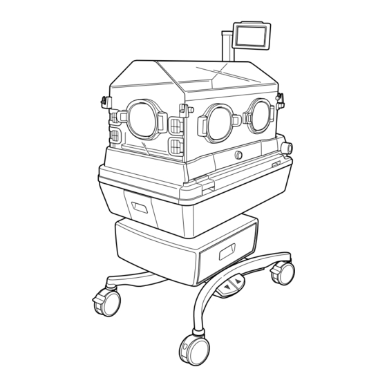
Equipment for neonatal and premature infants: Incubator
Atom Infant Incubator Model 101
0123
Advertisement
Table of Contents
Troubleshooting

Subscribe to Our Youtube Channel
Related Manuals for Atom Incu i 101


Summary of Contents for Atom Incu i 101
- Page 1 If repairs seem to be required as a result of any inspection described in this Manual, either personnel with more advance knowledge and skills should un- dertake the repair or you should contact your local Atom representative for re- pair service.
- Page 2 EU OFFICE Via F. Croce, 65 - 20081 Abbiategrasso (MI) - Italy Tel: +39 02 99763101 Fax: +39 02 99763110...
-
Page 3: Introduction
1) Ask someone who has completed a training course specified by Atom and who has sufficient technical knowledge and skills to do the work. 2) Ask Atom to send its service engineer if a person who has completed a training course specified by Atom and who has sufficient technical knowledge and skills is not available. - Page 4 x Definitions of Warning Indication Three levels of warning indication are used throughout this Manual and on the unit. They are defined as follows. A DANGER notice indicates an immediately hazardous situation which, if not avoided, DANGER: will result in death or serious injury, serious damage to property such as total loss of use of equipment or fire.
- Page 5 3. Symbols to give instructions for action Symbol Title and indication General instruction Indicates unspecified general action on the part of the user. Connect a ground wire Instructs the user to connect the ground wire without fail where the unit is provided with a ground terminal.
- Page 6 5. Other symbols Symbol Title and indication Setting Indicates that a setting is increased. Setting Indicates that a setting is decreased. Main screen display switch Indicates a switch to display the main screen. Trend screen display switch Indicates a switch to display the trend screen. Menu screen display switch Indicates a switch to display the menu screen.
- Page 7 Symbol Title and indication Humidity chamber off Indicates that the humidity chamber is not attached properly. Humidity Indicates the function related to humidity. Oxygen Indicates the function related to oxygen. Load capacity Indicates the maximum load capacity. Avoid getting caught Indicates that the user must avoid getting caught in the gap in the device.
-
Page 8: Table Of Contents
CONTENTS 5-3-2. Troubleshooting When the Unit INTRODUCTION ............ 1 Does Not Function Properly ....71 4-5. Others ............78 PLEASE READ WITHOUT FAIL [1] Operating Precautions ....... 8 DISASSEMBY AND REPLACEMENT DANGER ............ 8 1-1. Disassembly and Replacement WARNING ..........9 1-2. - Page 9 6-3-12. Replacing the Humidity Chamber 6-5-12. Replacing the Connector Cradle ..........115 Cap A/B ..........138 6-3-13. Replacing the Humidity Chamber 6-6. Mattress Platform ........139 Cover ........... 116 6-6-1. Replacing the Baby Guard/Side 6-3-14. Replacing the Humidity Chamber Baby Guard ........139 Cover Packing C ........
-
Page 10: Operating Precautions
Operating Precautions [1] Operating Precautions Please follow the operating instructions described in this Service Manual & Parts List for the safe use of the unit. The unit should be operated only by those who have been trained and instructed properly in its operation. The unit should be operated only for its intended use. -
Page 11: Warning
Operating Precautions Ground the unit securely. Otherwise, a leakage current may cause an electric shock. In order to complete the ground connection, connect the power cord only to a properly grounded 3P power outlet including a ground terminal. Do not operate the unit if you have any doubt about its ground connection. - Page 12 Operating Precautions If the oxygen sensor should break or get damaged, the electrolyte inside may leak out of the sensor. If you should come in contact with the electrolyte, wash it away immediately and thoroughly with copious amounts of water. Smoking is prohibited in the room where the unit is installed.
-
Page 13: Caution
60601-1-1 on his or her own responsibility. If in doubt, consult your local Atom representative. 1-3. - Page 14 Pressing it strongly or rubbing it may damage the display or cause it to malfunction. Be careful not to let any medical fluid adhere to the control panel. Do not attach any peripheral device that is not specified by Atom to the incubator. Check the operation of the peripheral devices.
-
Page 15: Parts Identification
Parts Identification [2] Parts Identification 2-1. Main Body Name Name Control panel X-ray cassette tray door locking knob Semi-iris access port Pedal for height adjustment Dovetail rail Caster Sensor module Drawer Admittance panel operating lever Humidity chamber cover Snap-open access port Mattress Admittance panel Tube introduction slit assembly... - Page 16 Parts Identification í Rear Name Name Skin temperature probe connecting port 1 Oxygen supply port 2 Skin temperature probe connecting port 2 Connector for the weight monitor Power switch Connector for the control panel Connector for the sensor module Connector for the Power Pack i (UPS) Filter cover Power cord inlet Oxygen supply port 1...
- Page 17 Parts Identification í Inside Name Mattress platform X-ray cassette tray Weight monitor unit Mattress platform for the weight monitor Tray for the weight monitor Mattress platform tray Middle board Fan cover Heater Baby guard Tube introduction slit assembly Note: #1 Weight monitor unit is optionally available.
-
Page 18: Control Panel
Parts Identification 2-2. Control Panel í Front í Rear í Bottom Name Alarm lamp Operation display Power failure alarm indicator I/O port (External communication connector) Connector for the main body Communication port (LAN) -
Page 19: Display Screens
Parts Identification 2-3. Display Screens 2-3-1. General Description of the Screens Start screen The start screen appears when the power is applied. [Main screen] This screen appears first. If any other screen is being displayed, touch the switch, and the main screen will be displayed. This screen displays the set temperature, the incu- bator air temperature, the skin temperature 1, the skin temperature 2, the relative humidity, the oxy-... - Page 20 Parts Identification (5) [Trend screen] Touch the switch on any other screen, and the trend screen will be displayed. This screen displays trend graphs. (6) [Menu screen] Touch the switch on any other screen, and the menu screen for advanced settings will be displayed. Use this screen to select advanced settings.
-
Page 21: Screen Transition Diagram
Parts Identification 2-3-2. Screen Transition Diagram Pulse oximeter screen Weight screen Main screen Menu screen Trend screen : [Main screen] display switch : [Pulse oximeter screen] display switch : [Weight screen] display switch Start Screen : [Trend screen] display switch : [Menu screen] display switch... -
Page 22: List Of Operations Available On Each Screen
Parts Identification 2-3-3. List of Operations Available on Each Screen Table 1. List of Setting Operations Available on Each Screen Pulse Setting (measuring) Trend Main Menu Weight oximeter ❋2 ❋1 Operation screen screen screen screen screen Temperature-related operation (manual/servo) Setting humidity Setting oxygen control Setting SpO /pulse rate... - Page 23 Parts Identification [Temperature area] ❋ Touch this area to start the temperature-related setting operation. Name Description Displays a detected skin tem- Skin tempera- perature 1 digitally. ture 1 display Displays a set incubator air tem- perature in manual control. Set tempera- Displays a set skin tempera- ture display ture 1 in servo control.
- Page 24 Parts Identification [Pulse area] ❋ Touch this area to start the pulse oximeter-related setting operation. Name Description Indicates changes in the arte- Plethysmo- rial flow. graph bar %SpO Displays a detected SpO value digitally. display Pulse rate Displays a detected pulse rate digitally.
-
Page 25: Pulse Oximeter Screen
Parts Identification [Clock and other indicators area] Name Description Touch this switch to silence an active audible alarm tempo- Alarm silence rarily or reset an alarm condi- switch tion. Displays a date in the month/ Date display day/year format. D i s p l a y s a t i m e i n t h e Time display hour:minute format. - Page 26 Parts Identification [Numerical values area] ❋ Touch an appropriate area (the temperature area, the relative humidity area, or the oxygen area) to start the area-related setting operation. (You can follow the same procedure as on the main screen.) Name Description Incubator air Displays a detected incubator temperature...
- Page 27 Parts Identification [Pulse area] ❋ Touch this area to start the pulse oximeter-related setting operation. Name Description Displays a detected SpO value %SpO digitally. display Displays an SpO upper alarm alarm limit above and an SpO lower limits display alarm limit below digitally. Displays a detected pulse rate Pulse rate digitally.
- Page 28 Parts Identification ❋ The higher the SatSeconds limit is set, the longer it takes for the upper or lower limit alarm to occur. Set the SatSeconds limit appropriately by taking into consideration the patient’s condition. For example, select a higher setting for monitoring an active patient whose %SpO values tend to fluctuate greatly.
-
Page 29: Weight Screen
Parts Identification 2-3-6. Weight Screen ❋ The weight screen is displayed only when the unit is equipped with the weight monitor unit. Weight area (See p.35) Numerical values area (See p.34) ❋ Message area (See p.30) Clock and other indicators area (See p.30) Screen display switch area (See p.29) - Page 30 Parts Identification [Weight area] [Weight area] Name Description Displays a message related to weighing when weighing is in progress. Weight Displays a weight reading of display area the infant when weighing is not in progress. Touch this switch to star t Weigh switch weighing the infant automati- cally.
-
Page 31: Menu Screen
Parts Identification 2-3-7. Menu Screen Menu area (See p.37) Numerical values area (See p.34) ❋ Message area (See p.30) Clock and other indicators area (See p.30) Screen display switch area (See p.29) ❋ The screen display switch area, the clock and other indicators area, and the message area are the same as those of the main screen (“2-3-4. - Page 32 Parts Identification [Menu area 1] ❋ This screen appears first when the menu screen is selected. Name Description Touch this switch to delete the Delete Trend trend data displayed on the Data switch trend screen. Touch this switch to delete the Delete weight data displayed on the Weight Data...
- Page 33 Parts Identification [Menu area 2] ❋ Select [Next] in the menu area 1 to enter this screen. Name Description Touch this switch to set the LCD Screen brightness of the display Brightness screen to a desired level. selector switch Touch this switch to set the Light Sensor light sensor level to a desired Level selector...
- Page 34 Parts Identification [Menu area 3] ❋ Select [Pulse Oximeter] in the menu area 1 to enter this screen. <The unit equipped with the Masimo pulse oximeter> Name Description Touch this switch to set the Synchronizing Pulse Beep volume of the synchronizing pulse beep of the pulse oxime- volume ter to a desired level.
-
Page 35: Trend Screen
Parts Identification 2-3-8. Trend Screen Trend area (See p.41) Numerical values area (See p.34) ❋ Message area (See p.30) Clock and other indicators area (See p.30) Screen display switch area (See p.29) ❋ The screen display switch area, the clock and other indicators area, and the message area are the same as those of the main screen (“2-3-4. - Page 36 Parts Identification [Trend area] Name Description A temperature scale (the incu- bator air temperature, the skin temperature 1 and the skin temperature 2) is provided on the left axis and a % scale (the Trend 1 relative humidity and the oxy- gen concentration) is provided on the right axis to display a trend graph of each item.
-
Page 37: Service Menu (How To Operate The Service Menu Screen)
Parts Identification 2-4. Service Menu (How to Operate the Service Menu Screen) (The service menu is not accessible to ordinary users.) 2-4-1. How to Enter the Service Menu Touch on any other screen, and the menu screen will appear. Touch “Service Menu” on the menu screen. When the password entry screen is displayed, touch the numeric keys in the following order: “3”... -
Page 38: Operating The Service Menu Screen
Parts Identification 2-4-2. Operating the Service Menu Screen 2-4-2-1. Setting the Key Click Sound (1) Touch [Key Click Sound] on the Ser vice Menu screen (1/2). (2) When the key click sound has been disabled before- hand, a message to confirm whether to enable the key click sound will appear. - Page 39 Parts Identification 2-4-2-3. Setting the MC Alarm Threshold Touch [MC Alarm Threshold] on the Service Menu screen (1/2). When the threshold has been set to 3.0˚C before- hand, a message to confirm whether to change it to 1.5˚C will appear. Touch , and the threshold will be changed to 1.5˚C.
- Page 40 Parts Identification 2-4-2-6. Checking How Many Days the Oxygen Sensors Have Been Used (1) Touch [O sensor days of use RESET] on the Ser- vice Menu screen (2/2). (2) The number of days for which the oxygen sensors have been used so far and a message to confirm whether to reset the counter will appear.
- Page 41 Parts Identification After the weight reading has stabilized, touch and a message “With the Weight Placed, Touch the Reweigh switch” will appear. Place a 5 kg standard weight gently on the center of the bed and wait for 5 ~10 seconds until the weight reading stabilizes. After the weight reading has stabilized, touch Reweigh and the 5kg adjustment will be completed.
- Page 42 Parts Identification 2-4-3. Calibrating the Touch Panel (1) Turn the power on and the start screen will appear. Touch this screen three times. (2) A message “Touch Screen Calibration. Point to the dot” will appear. Touch the dot displayed on the up- per left corner of the screen.
-
Page 43: Maintenance Inspection
1) Ask someone who has completed a training course specified by Atom and who has sufficient technical knowledge and skills to do the work. 2) Ask Atom to send its service engineer if a person who has completed a training course specified by Atom and who has sufficient technical knowledge and skills is not available. -
Page 44: Inspection Before Use
If you should notice any strange smell, strange noise, overheating or strange vibration when the power is applied to the main body in the inspection before use, stop using the unit immediately and contact your local Atom representative. 3-1-1. Visual Inspection... -
Page 45: Functional Inspection
❋ Dead pixels (points on the screen that are always dark) may be found on the LCD display during the inspec- tion. This is a phenomenon peculiar to an LCD display and not a malfunction. However, if an important message or a numerical value is not visible due to too many dead pixels, contact your local Atom represen- tative. - Page 46 Maintenance Inspection (Checking the displays and the audible alarm) (3) Turn on the power switch to activate the system. Power switch Check: q Does the alarm lamp come on and does the au- dible alarm sound immediately after the power switch is turned on? w Is a numerical value displayed on the incubator air temperature display?
- Page 47 Maintenance Inspection (Checking the oxygen controller (for the unit with the oxygen controller)) Enable the oxygen controller function. Check: q Is a numerical value displayed on the oxygen concentration display? While pressing the lever, pull out the sensor mod- ule and perform the 21% calibration procedure. Lever Check: q Is “21%”...
-
Page 48: Performance Inspection
Maintenance Inspection (18) Touch (19) Touch again while a message “Lift up baby from mattress” is displayed with a melody . Check: q Does the tare deduction process start and does the unit enter the ordinary weight monitor mode? w Does the weight reading change when you push down the mattress platform lightly in the ordinary weight monitor mode? (Inspection completed) (20) Turn off the power switch. -
Page 49: Checking And Calibrating The Weight Monitor
Maintenance Inspection (Oxygen supply) (12) Supply oxygen through the oxygen supply port 1 at 10L/min using an oxygen flowmeter. Check: q Measure the oxygen concentration with an oxygen monitor. Is the reading at least 65% O ❋ Stop the oxygen supply when checking is completed. (Humidity control) (13) Set the relative humidity to 90%RH. -
Page 50: Quarterly Inspection
Maintenance Inspection 3-2. Quarterly Inspection Check the following items every three months. Item to check Procedure Description Set the temperature to 36.0˚C in manual The displayed incubator air temperature Incubator air control. should be stable at 36.0 1˚C. temperature control Place the skin temperature probe at about 10cm above the center of the mattress The displayed skin temperature should... -
Page 51: Inspection Checklist
If any trouble is detected in any inspection, indicate on the unit that it is out of order and seek repair without fail. Contact your local Atom representative for further information on repairs. Serial No. ( Date of Inspection (... -
Page 52: Periodical Replacement Parts And How To Replace Them
Periodical replacement parts are those which gradually deteriorate and wear down with use. They need peri- odical replacement to keep the accuracy and performance of the unit at a proper level. Timing of replacement varies with the frequency and conditions of use. Consult your local Atom representative for replacement. Part name... -
Page 53: Replacing The Filter
When the time comes to replace the filter, a message appears on the screen to remind the user. The counter must be reset after the filter is replaced. Otherwise, the message will remain on. Be sure to contact your local Atom representative if you have replaced the filter yourself. -
Page 54: Replacing The Oxygen Sensor
Maintenance Inspection 3-4-2. Replacing the Oxygen Sensor WARNING As part of daily inspection, check the oxygen sensor for any sign of deterioration or liquid leakage. If any cracks should be found on the external surface, replace it immediately with a new one. The oxygen sensor is a sealed device containing a potassium hydroxide electrolyte. - Page 55 The counter must be reset after the oxygen sensors are replaced. Otherwise, the message will remain on. Be sure to contact your local Atom representative if you have replaced the oxygen sensors yourself.
-
Page 56: Cleaning And Disinfection
Cleaning and Disinfection [4] Cleaning and Disinfection WARNING Before cleaning and disinfecting the unit, be sure to turn the power off, remove the power plug from the power outlet, and allow the incubator and the heaters to cool down sufficiently. CAUTION This product is shipped without being disinfected. -
Page 57: Hood Assembly
Cleaning and Disinfection 4-1. Hood Assembly • Snap-open access port packing Frame Remove the rubber packings from the snap-open access Packing lip ports. Immerse and clean them in a disinfectant solution. To replace each rubber packing to its former position, be sure to smooth out wrinkles along the packing lip so that the access port packing will fit perfectly in the groove around the frame of the snap-open access port as shown in the fig-... - Page 58 Cleaning and Disinfection • Access port cover Remove all the access port covers. Immerse and clean them in a disinfectant solution. CAUTION b Spare access port covers should always be on hand. A dirty cover should be replaced immedi- ately with a new one. •...
-
Page 59: Mattress Platform And Parts Beneath
Cleaning and Disinfection • Control panel Control panel: Clean the control panel with a soft cloth damp- ened with a disinfectant solution. LCD display (the surface of the liquid crystal panel): Clean the LCD display lightly with a dry cloth. Use a specified dis- infectant solution when necessary. - Page 60 Cleaning and Disinfection To replace the mattress platform tray to its former position, Mattress platform tray make sure that it is engaged securely with the tilting arm. Tilting arm • Middle board Middle board Fan cover With the admittance panels on both sides open, grasp one end of the middle board with one hand and the concave por- tion of the fan cover with the other hand.
-
Page 61: Humidity Chamber
Cleaning and Disinfection • Conditioning chamber The conditioning chamber will become accessible when all the components mentioned above have been removed. Pull up the heater and clean the inside of the conditioning cham- ber thoroughly with a soft cloth dampened with a disinfec- tant solution. -
Page 62: Others
Cleaning and Disinfection Never immerse the humidity chamber in a disinfec- tant solution. Boiler WARNING b The humidity chamber contains electric parts. Never immerse the humidity chamber in a disin- Water level fectant solution. Do not rub the water level sen- sensor sor or the surface of the boiler of the humidity chamber with a metal brush or any other hard... -
Page 63: Troubleshooting
This incubator is provided with the following alarms. If an alarm condition should occur, check for a possible cause of the alarm and take the proper measures. If the incubator seems to be defective, it is in need of repairs. Indicate on the incubator that it is out of order and contact your local Atom representative. - Page 64 Troubleshooting Cat- Condition causing The unit during the Resetting the Alarm Alarm name Message Priority egory the alarm alarm condition alarm silence Check that the The alarm will be reset This alarm will occur The humidifying humidity cham- automatically when if the humidity cham- heater will be ber is attached...
- Page 65 Troubleshooting Cat- Condition causing The unit during the Resetting the Alarm Alarm name Message Priority egory the alarm alarm condition alarm silence The alarm will be Pulse Oximeter This alarm will occur reset automatically reading has if the SpO upper M e a s u r e m e n t upper when the SpO...
- Page 66 Troubleshooting Cat- Condition causing The unit during the Resetting the Alarm Alarm name Message Priority egory the alarm alarm condition alarm silence The alarm will be This alarm will occur Pulse Oximeter “0” will be dis- reset automatically when it is difficult to High 2 min.
- Page 67 Troubleshooting Cat- Condition causing The unit during the Resetting the Alarm Alarm name Message Priority egory the alarm alarm condition alarm silence This alarm will occur if the sensor module is left removed for 15 seconds or longer af- Place the sensor The fan will con- Replace the sensor ter calibration, or if it...
- Page 68 Troubleshooting Cat- Condition causing The unit during the Resetting the Alarm Alarm name Message Priority egory the alarm alarm condition alarm silence This alarm will occur if the power supply is inter r upted due to power failure, a dis- Impos- No message (The connected power plug,...
-
Page 69: Troubleshooting
5-2. Troubleshooting WARNING If the unit seems to be defective, indicate on the unit that it is out of order, stop using it immediately, and contact your local Atom representative. CAUTION Check the following points before requesting repair service. Trouble... - Page 70 Troubleshooting Trouble Action to take Check that the relative humidity is not extremely high due to the rainy Humidity rises too high. season or some other cause. Check that oxygen is being supplied reliably (when the oxygen controller is in use). The oxygen concentration Check that the flow rate is set properly on the oxygen flowmeter.
-
Page 71: Troubleshooting Flowchart
Troubleshooting 5-3. Troubleshooting Flowchart ❋ The description in this section relates to a unit which is equipped with an oxygen controller and a weight monitor unit (not requiring official verification). Please skip any reference unrelated to your unit. 5-3-1. Troubleshooting When the Unit Cannot Be Controlled Properly Trouble Action to take 1. - Page 72 Troubleshooting Trouble Action to take 1. Check that the flow rate is not set too low on the oxygen flowmeter. 2. Check that the access ports are closed securely. 3. Check that all the packings are attached securely. 4. Check that the filter is attached securely. The oxygen concentration When the oxygen controller is in use: does not rise.
-
Page 73: Troubleshooting When The Unit Does Not Function Properly
Troubleshooting 5-3-2. Troubleshooting When the Unit Does Not Function Properly When any of the following messages is displayed on the screen: q “Abnormality in yellow skin temperature probe” w “Check the connection of the yellow skin temperature probe.” e “Check that the humidity chamber is attached properly.” r “Close the humidity chamber cover.”... - Page 74 Troubleshooting (1) When any of the following messages is displayed on the screen: q “Abnormality in yellow skin temperature probe” The alarm is still displayed even after the skin temperature probe is Failure of the skin temperature replaced with a functional one. Failure of the detection board w “Check the connection of the yellow skin temperature probe.”...
- Page 75 Troubleshooting e “Check that the humidity chamber is attached properly.” The humidity chamber is fit in. Fit in the humidity chamber. The boiler cap is attached to the Attach the boiler cap to the humidity humidity chamber. chamber. The humidity chamber is inserted Insert the humidity chamber completely into the unit.
- Page 76 Troubleshooting r “Close the humidity chamber cover.” The humidity chamber cover is Close the humidity chamber cover. closed. The humidity chamber cover is Defect of the humidity chamber damaged. cover The connector of the position Connect the connector of the detection board is connected position detection board securely.
- Page 77 Troubleshooting t “Fill humidity chamber with sterile distilled water.” The cartridge tank is filled with a Add more sterile distilled water in sufficient volume of sterile distilled the cartridge tank. water. The alarm message is still displayed even after the humidity Failure of the humidity chamber chamber is replaced with a functional one.
- Page 78 Troubleshooting y “Humidity sensor condensing.” Condensation has formed on the Dry the humidity sensor. humidity sensor. The cable of the sensor module is Connect the connector of the cable connected properly to the sensor of the sensor module securely. module connecting port. The alarm message is still displayed even after the sensor Failure of the sensor module...
- Page 79 Troubleshooting u “Humidifying heater abnormal (E8)” The alarm message is still displayed even after the humidity Failure of the humidity chamber chamber is replaced with a functional one. The cable of the humidity chamber Connect the cable of the humidity connector is connected properly.
-
Page 80: Others
Troubleshooting i “Incubator humidity deviates from the set humidity.” The relative humidity in the Select a higher humidity setting or incubator has risen due to the turn the humidity control off. infant’s insensible water loss. The snap-open access ports and Close the access ports and the the admittance panels are intact admittance panels securely. - Page 81 Troubleshooting o “O sensor (L) failed calibration.” !0 “O sensor (R) failed calibration.” Recalibrate the sensor. The alarm message disappears. Nothing abnormal Both of the oxygen sensors are Connect the oxygen sensors connected properly to the sensor securely. module. The connector pin of the oxygen Replace the oxygen sensors.
- Page 82 Troubleshooting !1 “Oxygen concentration in incubator deviates from the set value.” The supply pressure of the oxygen Adjust the supply pressure of the from the oxygen supply port 2 is oxygen to the normal range within the normal range (294~490kPa). (294~490kPa).
- Page 83 Troubleshooting !2 “No oxygen delivered.” The supply pressure of the oxygen Adjust the supply pressure of the from the oxygen supply port 2 is oxygen to the normal range within the normal range (294~490kPa). (294~490kPa). The hose connected to the oxygen Replace the piping connecting hose.
- Page 84 Troubleshooting !3 “Pulse Oximeter: Check the patient cable connection.” !4 “Pulse Oximeter: Check the sensor connection.” The SpO sensor/the patient cable Connect the SpO sensor/the is connected properly. patient cable securely. The SpO sensor/the patient cable Replace the SpO sensor/the has a broken wire.
- Page 85 Troubleshooting !9 “Place the sensor module back in its proper place.” The sensor module is pulled out for Place the sensor module back in its 21% calibration. proper place for normal operation. The connector of the sensor Connect the connector of the module is connected properly.
- Page 86 Troubleshooting @1 “Disconnect power and check the fan is properly attached.” Turn off the power switch. The fan, the middle board and the Attach the fan, the middle board fan cover are attached. and the fan cover. The fan, the middle board or the fan Replace the fan, the middle board cover is damaged.
- Page 87 Troubleshooting @2 “Check the fan cover is properly attached.” Turn off the power switch. The middle board and the fan cover Attach the middle board and the fan are attached. cover. The middle board or the fan cover is Replace the middle board or the fan visibly damaged.
- Page 88 Troubleshooting @4 “Abnormality in the incubator air temperature sensor is detected. (E262)” @5 “Abnormality in the incubator air temperature sensor is detected. (E263)” The connector of the sensor module is connected properly to the Connect the connector securely. sensor module connecting port. The alarm message is still displayed even after the sensor Failure of the sensor module.
- Page 89 Troubleshooting @7 “Communication to the main body abnormal. (E1025)” The cable connecting the control Replace the cable. panel with the main body is defective. Failure of the control board @8 “Internal system abnormal. (E10)” Failure of the heater control board @9 “Internal system abnormal.
- Page 90 Troubleshooting #1 “Select your desired temperature.” #2 “Select your desired humidity.” #3 “Select your desired oxygen concentration.” Select a desired setting. Failure of the control board if the alarm message is displayed every time the power is turned on. #4 “Weighing scale abnormal. (E**)” Power cycle the incubator.
- Page 91 Troubleshooting When no message is displayed on the screen: q The power failure alarm indicator is flashing red. An audible alarm (pip pip pip…pip pip) is given from the buzzer of the main body. Restore the power supply to the The power supply to the installation installation site (room).
- Page 92 Troubleshooting w The control panel blacks out and nothing is displayed.(The screen is blank.) See (2) q “The power failure alarm The power failure alarm indicator is flashing red. indicator is flashing red.” The control panel connecting cable Connect the cable securely. is connected properly without a If the cable has a broken wire, broken wire.
- Page 93 Troubleshooting e The control panel does not respond when the screen is touched. Interference is occurring between Correct the attachment of the LCD the touch panel and the front panel. module. Calibrate the touch panel. See “2-4-3. Calibrating the Touch Calibration failure of the touch panel Panel.”...
- Page 94 Troubleshooting t No audible alarm is given in a power failure alarm condition. See (2) r “No audible alarm is No audible alarm is given even in given.” normal use. The rechargeable battery on the A power failure alarm occurred recently.
- Page 95 The weight monitor function has not The weight screen display switch been set yet or is set incorrectly. appears on the screen. Contact your local Atom representative. See (2) e “The control panel does not respond when the screen is touched.”...
- Page 96 Troubleshooting o The HL stand is not adjustable vertically. The unit is being switched from the incubator mode to the radiant warmer mode or vice versa. Burnout due to continuous The HL stand has been operated continuously for more than 2 operation ...
-
Page 97: Disassembly And Replacement Procedures
Disassembly and Replacement Procedures [6] Disassembly and Replacement Procedures Before disassembling and replacing the components of the unit, be sure to turn the power off, remove the power cord from the power cord inlet, and allow the incubator and the heaters to cool down sufficiently. After completing the following procedures, perform the functional inspection according to “3-3. - Page 98 Disassembly and Replacement Procedures (5) Pull out the power box. Power box (6) Remove the wiring. Remove the connectors JQ7 and JQ8 from the height adjustment drive board. For details, see “[8] Wiring diagram.” (7) Tilt the main body and pull out the cables through the hole in the bottom of the main body.
-
Page 99: Replacing The Actuator
Disassembly and Replacement Procedures 6-1-2. Replacing the Actuator Remove the main body from the HL stand. See (1) ~ (8) in “6-1-1. Removing the Main Body from the HL Stand.” Remove the HL stand table. TORX screws ( φ8x80) Remove the cable from the connector on the upper part of the actuator and then remove the cable clamp fixed with a screw. -
Page 100: Pedals For Height Adjustment
Disassembly and Replacement Procedures (3) Remove the foot switch from the HL stand base. Use a hexagon wrench (distance between the oppo- Hexagon socket head cap screws site sides: 6mm) and remove the two hexagon socket (M8x40) with spring washers (M8) head cap screws (M8 x 40) along with the spring washers (M8). -
Page 101: Replacing The Caster
Disassembly and Replacement Procedures 6-1-4. Replacing the Relay Board of the Pedals for Height Adjustment Follow the steps described in “6-1-3. Replacing the Foot Switch” except for (3). Remove the relay board of the pedals for height ad- justment. Remove the double sems screw (M3 x 8) with a Phillips screwdriver and a wrench (distance between the opposite sides: 5.5mm) and then re- move all the connectors from the relay board of the... -
Page 102: Hood
Disassembly and Replacement Procedures 6-2. Hood 6-2-1. Replacing the Hood Assembly (1) Remove the rear panel of the main body. See (1) ~ (3) in “6.1.1 Removing the Main Body from the HL Stand.” (2) Remove the control box cover. Remove the four protective stickers and then remove Flat head screw (M4x12) the four flat head screws (M4 x 12) with a Phillips... -
Page 103: Replacing The Admittance Panel Lock Holder
Disassembly and Replacement Procedures Remove the hood assembly. Remove the four protective stickers and the sheet Flat head screw (M4x12) on the head side of the hood. Remove the three flat head screws (M4 x 12) with a Phillips screwdriver. Remove the five double sems screws (M4 x 15) on Double sems screw (M4x15) the foot side of the hood with a Phillips screwdriver. -
Page 104: Replacing The Snap-Open Access Port S/W
Disassembly and Replacement Procedures 6-2-4. Replacing the Snap-open Access Port S/W (1) Remove the snap-open access port S/W. Remove the protective sticker and then remove the two flat head screws (M4 x 12) with a Phillips screwdriver. Flat head screw (M4x12) Protective sticker With the snap-open access port open, detach it from the three claws on its base. -
Page 105: Replacing The Admittance Panel Hinge (With X-Ray Cassette Tray Door)
Disassembly and Replacement Procedures 6-2-6. Replacing the Admittance Panel Hinge (with X-ray Cassette Tray Door) Remove the admittance panel hinge cover. Remove the protective stickers affixed to the admit- Double sems screw (M3x10) tance panel hinge cover and then remove the six double sems screws (M3 x 10) with a Phillips screw- driver. -
Page 106: Replacing The Admittance Panel Operating Lever R/L
Disassembly and Replacement Procedures 6-2-7. Replacing the Admittance Panel Operating Lever R/L (1) Remove the admittance panel operating lever. Remove the two pan head tapping screws (M3 x 14) with a Phillips screwdriver and then remove the admittance panel operating lever. Pan head tapping screw (M3x14) (2) Follow the same procedure mentioned above to re- move the admittance panel operating levers on the... -
Page 107: Replacing The Inner Wall Lever R/L
Disassembly and Replacement Procedures 6-2-9. Replacing the Inner Wall Lever R/L Remove the inner wall lever. Remove the pan head tapping screw (M3 x 10) with a Phillips screwdriver. Slide the inner wall lever from the admittance panel and remove it. Pan head tapping screw (M3x10) Follow the same procedure mentioned above to re- move the inner wall levers on the other admittance... -
Page 108: Replacing The Inner Wall Bearing
Disassembly and Replacement Procedures 6-2-11. Replacing the Inner Wall Bearing (1) Remove the inner wall. See (1) ~ (2) in “6-2-10. Replacing the Inner Wall (for the Incu i ).” (2) Remove the admittance panel hinge (with X-ray cas- sette tray door). See (1) ~ (3) in “6-2-6. -
Page 109: Main Body
Disassembly and Replacement Procedures 6-3. Main Body 6-3-1. Removing the Upper Section of the Main Body from the Main Body Remove the rear panel of the main body and pull out the power box. See (1) ~ (5) in “6-1-1. Removing the Main Body from the HL Stand.”... -
Page 110: Replacing The Heater
Disassembly and Replacement Procedures (4) Remove the steam gate. Open the humidity chamber cover and remove the steam gate. Steam gate (5) Remove the upper section of the main body. Remove the four hole plugs and then remove the four hexagon socket head cap screws (M6 x 15) with a hexagon wrench (distance between the opposite sides: 5mm). -
Page 111: Replacing The Motor
Disassembly and Replacement Procedures Reassembly: Reassemble in the reverse order of dis- assembly. CAUTION b Be sure to attach a new packing when replacing the heater. 6-3-3. Replacing the Motor Remove the fan. Hold the fan with both your hands and pull it out along the motor shaft. -
Page 112: Replacing The High Temperature Sensor
Disassembly and Replacement Procedures (4) Reassembly: Reassemble in the reverse order of dis- assembly. When reassembling the motor, be sure to attach the connector of the motor in the correct orientation and take care not to get the wires caught. CAUTION b Be sure to attach a new packing when replacing the motor assembly. -
Page 113: Replacing The Control Box Cover
Disassembly and Replacement Procedures 6-3-5. Replacing the Control Box Cover Remove the rear panel of the main body. See (1) ~ (3) in “6-1-1. Removing the Main Body from the HL Stand.” Remove the control box cover from the hood. Remove the four flat head machine screws (M4 x Flat head machine screw (M4x12) -
Page 114: Replacing The Detection Board
Disassembly and Replacement Procedures (3) Remove the connector from the control board (for the Dual Incu i). If the unit contains the SpO module, see (2) and (3) Connector (JA19) in “6-4-1. Replacing the Control Board (for the Dual Incu i ).” Remove the connector (JA19) from the control board (for the Dual Incu i ). -
Page 115: Replacing The Tilting Unit
Disassembly and Replacement Procedures 6-3-8. Replacing the Tilting Unit Remove the control box cover. See (1) ~ (3) in “6-3-5. Replacing the Control Box Cover.” Remove the tilting arm. Remove the two setscrews (M6) with a hexagon wrench (distance between the opposite sides: 3mm). Move the V ring toward the tilting unit. -
Page 116: Replacing The Filter Joint
Disassembly and Replacement Procedures (3) Remove the position detection board. Remove the washer head (M3 x 10) with a Phillips Connector screwdriver and then remove the connector. Washer head (M3x10) (4) Reassembly: Reassemble in the reverse order of dis- assembly. 6-3-10. -
Page 117: Replacing The Humidity Chamber Cover Packing A
Disassembly and Replacement Procedures 6-3-11. Replacing the Humidity Chamber Cover Packing A Remove the upper section of the main body from the main body. See (1) ~ (5) in “6-3-1. “Removing the Upper Sec- tion of the Main Body from the Main Body.” Remove the humidity chamber cover packing A from Humidity chamber the upper section of the main body. -
Page 118: Replacing The Humidity Chamber Cover
Disassembly and Replacement Procedures (3) Remove the humidity chamber cradle. Remove the six resin tapping screws (M3 x 12) with a Phillips screwdriver. (The picture on the right shows one side only.) Pull up the humidity chamber cradle and remove the connectors of the position detection board (for the detection of the humidity chamber cover and the boiler cap). -
Page 119: Replacing The Connector Of The Humidity Chamber
Disassembly and Replacement Procedures 6-3-15. Replacing the Connector of the Humidity Chamber Remove the humidity chamber cradle from the up- per section of the main body. See (1) ~ (3) in “6-3-12. Replacing the Humidity Chamber Cradle.” Remove the humidity chamber cover. Remove the eight tapping screws (M3 x 8) with a Phillips screwdriver. -
Page 120: Replacing The Position Detection Board (For The Detection Of The Humidity Chamber Cover)
Disassembly and Replacement Procedures 6-3-17. Replacing the Position Detection Board (for the Detection of the Humidity Chamber Cover) (1) Remove the humidity chamber cradle from the up- per section of the main body. See (1) ~ (3) in “6-3-12. Replacing the Humidity Chamber Cradle.”... -
Page 121: Replacing The Drive Power Transformer
Disassembly and Replacement Procedures Remove the control power transformer. Remove the four tapping screws (M4 x 14) with a Tapping screw (M4x14) Phillips screwdriver. Tapping screw (M4x14) Reassembly: Reassemble in the reverse order of dis- assembly. 6-3-19. Replacing the Drive Power Transformer Remove the upper section of the main body from the main body. -
Page 122: Replacing The Oxygen Controller Assembly
Disassembly and Replacement Procedures 6-3-20. Replacing the Oxygen Controller Assembly (1) Remove the rear panel of the main body. See (1) ~ (3) in “6-1-1. Removing the Main Body from the HL Stand.” (2) Remove the connectors from the control board (for the Dual Incu i). -
Page 123: Replacing The Solenoid Valve
Disassembly and Replacement Procedures Remove the pipes and the mass flow valve. Remove the two double sems screws (M3 x 8) with a Phillips screwdriver. Double sems screw (M3x8) Reassembly: Reassemble in the reverse order of dis- assembly. 6-3-22. Replacing the Solenoid Valve Remove the oxygen controller assembly. -
Page 124: Power Unit
Disassembly and Replacement Procedures 6-4. Power Unit 6-4-1. Replacing the Control Board (for the Dual Incu i ) (1) Pull out the power box. See (1) ~ (5) in “6-1-1. Removing the Main Body from the HL Stand.” (2) Remove the SpO unit. -
Page 125: Replacing The Battery
Disassembly and Replacement Procedures 6-4-2. Replacing the Battery Remove the control board (for the Dual Incu i). See (1) ~ (5) “6-4-1. Replacing the Control Board (for the Dual Incu i ).” Remove the battery. Cut the two leads of the battery soldered on the con- trol board (for the Dual Incu i) with pliers. -
Page 126: Replacing The Heater Control Board (For The Incu I )
Disassembly and Replacement Procedures 6-4-3. Replacing the Heater Control Board (for the Incu i ) (1) Pull out the power box. See (1) ~ (5) in “6-1-1. Removing the Main Body from the HL Stand.” (2) Remove the SpO unit and the SpO slide plate. - Page 127 Disassembly and Replacement Procedures Remove the coating clip on the side of the power box plate. <Protective earth terminal> Remove the five sems screws (M4 x 8) fixing the earth terminals of the upper section of the main body, the oxygen controller, the high temperature sensor, the warming heater and the humidifying heater with a Phillips screwdriver.
-
Page 128: Replacing The Power Cord Inlet
Disassembly and Replacement Procedures 6-4-4. Replacing the Power Cord Inlet (1) Remove the power box. See (1) ~ (3) in “6-4-3. Replacing the Heater Con- trol Board (for the Incu i ).” (2) Remove the connecting terminal of the power cord Sems screw (M3x6) inlet. -
Page 129: Replacing The Buzzer
Disassembly and Replacement Procedures 6-4-5. Replacing the Buzzer Pull out the power box and then remove the SpO unit and the SpO slide plate. See (1) ~ (2) in “6-4-3. Replacing the Heater Con- trol Board (for the Incu i ).” Remove the connector connected to the control board (for the Dual Incu i). -
Page 130: Replacing The Height Adjustment Drive Board
Disassembly and Replacement Procedures 6-4-7. Replacing the Height Adjustment Drive Board (1) Remove the power box. See (1) ~ (3) in “6-4-3. Replacing the Heater Con- trol Board (for the Incu i ).” (2) Remove the connector connected to the height ad- justment drive board. -
Page 131: Replacing The Fuse
Disassembly and Replacement Procedures 6-4-9. Replacing the Fuse Pull out the power box. See (1) ~ (5) in “6-1-1. Removing the Main Body from the HL Stand.” Remove the fuse. After pulling out the power unit, pull out the fuse with a flat head screwdriver. -
Page 132: Control Panel
Disassembly and Replacement Procedures 6-5. Control Panel 6-5-1. Replacing the Arm for Mounting the Function Rail (1) Remove the screws fixing the control panel and the arm. Remove the four sems screws (M3 x 8) with a Phillips screwdriver. Sems screw (M3x8) (2) Remove the screws fixing the cable guide. -
Page 133: Replacing The Front Panel
Disassembly and Replacement Procedures 6-5-3. Replacing the Front Panel Remove the cable. Loosen the two screws fixing the cable with a small Phillips screwdriver and remove the cable. Loosen the screw. Remove the rear panel. Remove the four sems screws (M3 x 8) with a Phillips screwdriver. -
Page 134: Replacing The Rear Panel (With Alarm Lamp)
Disassembly and Replacement Procedures 6-5-4. Replacing the Rear Panel (with Alarm Lamp) (1) Remove the cable. Loosen the two screws fixing the cable with a small Phillips screwdriver and remove the cable. Loosen the screw. (2) Remove the screws fixing the panel and the arm. Remove the four sems screws (M3 x 8) with a Phillips screwdriver. -
Page 135: Replacing The Lcd Module
Disassembly and Replacement Procedures 6-5-5. Replacing the LCD Module Remove the rear panel. See (1) ~ (2) in “6-5-3. Replacing the Front Panel.” Remove the connector connected to the LCD mod- ule. Remove the connector of the CCFL inverter and the tab of the touch panel. -
Page 136: Replacing The Speaker
Disassembly and Replacement Procedures 6-5-6. Replacing the Speaker (1) Remove the cable. Loosen the two screws fixing the cable with a small Phillips screwdriver and remove the cable. Loosen the screw. (2) Remove the rear panel. Remove the four sems screws (M3 x 8) with a Phillips screwdriver. -
Page 137: Replacing The Alarm Lamp Board
Disassembly and Replacement Procedures 6-5-7. Replacing the Alarm Lamp Board Remove the rear panel. See (1) ~ (2) in “6-5-3. Replacing the Front Panel.” Remove the alarm lamp board. Sems screw (M3x8) Remove the two sems screws (M3 x 8) with a Phillips screwdriver. -
Page 138: Replacing The Lcd Display Board
Disassembly and Replacement Procedures 6-5-9. Replacing the LCD Display Board (1) Remove the rear panel. See (1) ~ (2) in “6-5-3. Replacing the Front Panel.” (2) Remove the connectors connected to the LCD dis- play board. Remove the connectors (JB1, JB2, JB9, JB11, JB19) from the LCD display board. -
Page 139: Replacing The Ccfl Inverter
Disassembly and Replacement Procedures 6-5-10. Replacing the CCFL Inverter Remove the rear panel. See (1) ~ (2) in “6-5-3. Replacing the Front Panel.” Remove the CCFL inverter. Remove the two cables (upper and lower). Remove Cable the two double sems screws (M3 x 8) with a Phillips screwdriver. -
Page 140: Replacing The Connector Cap A/B
Disassembly and Replacement Procedures 6-5-12. Replacing the Connector Cap A/B (1) Remove the rear panel. See (1) ~ (2) in “6-5-3. Replacing the Front Panel.” (2) Remove the connector cap. Connector cap (3) Attach the connector cap. Insert the legs of the connector cap through the slots in the rear panel and pull them from inside the rear panel. -
Page 141: Mattress Platform
Disassembly and Replacement Procedures 6-6. Mattress Platform 6-6-1. Replacing the Baby Guard/Side Baby Guard Release the two stoppers fixing the baby guard/side baby guard and remove the baby guard/side baby guard. Push the center of the stopper head on one side and release the stopper. -
Page 142: Replacing The Weight Monitor Module
Disassembly and Replacement Procedures 6-6-3. Replacing the Weight Monitor Module (1) Remove the weight monitor module from the tray for the weight monitor. Remove the four truss screws (M4 x 10) with a Phillips screwdriver. Truss screw (M4x10) (2) Reassembly: Reassemble in the reverse order of dis- assembly. -
Page 143: Electrical Block Diagram
Electrical Block Diagram [7] Electrical Block Diagram... -
Page 144: Wiring Diagram
Wiring Diagram [8] Wiring Diagram 8-1. Drive Unit... -
Page 145: Main Body
Wiring Diagram 8-2. Main Body... -
Page 146: Peripheral Units
Wiring Diagram 8-3. Peripheral Units... -
Page 147: Parts List
Parts List [9] Parts List ❋ The description in this section relates to a unit which is equipped with a weight monitor. Please skip any reference unrelated to your unit. -
Page 148: Fig-1 Main Body And Accessories
Parts List 9-1. Fig-1 Main Body and Accessories Fig-1... - Page 149 Parts List Fig-No Part No. Part Name Control panel (with the arm for mounting to the function rail) 98521 Sensor module 98522 Sensor module (unit with oxygen controller) 98523 Humidity chamber AC100V 98524 Humidity chamber AC120V 98525 Humidity chamber AC230V 98526 Pneumoclean (electrostatic filter) (5 pcs/box) 32053...
-
Page 150: Fig-2 Control Panel
Parts List 9-2. Fig-2 Control Panel Fig-2... - Page 151 Parts List Fig-No Part No. Part Name Arm for mounting to the function rail 98533 Cable guide (with fixing screws) 98534 Front panel 98535 LCD module 98536 Rear panel (with alarm lamp) 98537 Button cell battery 98538 Speaker 98539 Connector cap B 98540 Connector cap A 98541...
-
Page 152: Fig-3 Humidity Chamber
Parts List 9-3. Fig-3 Humidity Chamber Fig-3... - Page 153 Parts List Fig-No Part No. Part Name Boiler cap 98547 Cartridge tank cap 98548 Cartridge tank (with cap) 98549 Humidity chamber handle (with spring) 98553...
-
Page 154: Fig-4 Mattress Platform
Parts List 9-4. Fig-4 Mattress Platform The unit with the weight monitor Fig-4... - Page 155 Parts List Fig-No Part No. Part Name Tube introduction slit assembly 92326 Baby guard 98554 Side baby guard 98555 Mattress platform (with X-ray cassette tray) 98556 Mattress platform tray (with latch) 98557 Latch 98558 Middle board (with fan cover) 98559 Mattress 21148 Level...
-
Page 156: Fig-5 Upper Section Of The Main Body 1
Parts List 9-5. Fig-5 Upper Section of the Main Body 1 Fig-5... - Page 157 Parts List Fig-No Part No. Part Name Foot-side hood cover 98692 Heater AC100V 98568 Heater AC120V 98569 Heater AC230V 98570 High temperature sensor 98571 Motor 98572 98573 Tilting unit 98574 Tilting knob R 98575 Tilting knob L 98576 Power switch 98577 5-10 Detection board...
-
Page 158: Fig-6 Upper Section Of The Main Body 2
Parts List 9-6. Fig-6 Upper Section of the Main Body 2 Fig-6... - Page 159 Parts List Fig-No Part No. Part Name Hood (with protective stickers) 98676 Admittance panel lock holder (left) 98712 Admittance panel lock holder (left?) 98713 Packing for fixing the semi-iris port frame 92249 Sensor module holder 98587 Tube introduction slit assembly 92326 Control box cover (with protective sticker) 98677...
-
Page 160: Fig-7 Upper Section Of The Main Body 3
Parts List 9-7. Fig-7 Upper Section of the Main Body 3 Fig-7... - Page 161 Parts List Fig-No Part No. Part Name Admittance panel (for the Incu i ) 98678 Inner wall (for the Incu i ) 98679 Inner wall bearing 98599 Snap-open access port W (with protective sticker) 21185 Admittance panel operating knob R (for the Incu i / Neo-Servo i ) 98723 Admittance panel hinge (with X-ray cassette tray door) 98602...
-
Page 162: Fig-8 Lower Section Of The Main Body
Parts List 9-8. Fig-8 Lower Section of the Main Body Fig-8... - Page 163 Parts List Fig-No Part No. Part Name Humidity chamber cradle 98610 Humidity chamber cover 98611 Humidity chamber cover packing C 98612 Humidity chamber connector 98613 Position detection board 98582 Oxygen controller 98615 Control power transformer AC100 ~120V 98616 Control power transformer AC230 98617 Drive power transformer AC100 ~120V 98618...
-
Page 164: Fig-9 Power Unit
Parts List 9-9. Fig-9 Power Unit Fig-9... - Page 165 Parts List Fig-No Part No. Part Name Control board (for the Dual Incu i ) 98620 Heater control board AC100V (for the Incu i ) (with fuse) 98686 Heater control board AC120V (for the Incu i ) (with fuse) 98687 Heater control board AC230V (for the Incu i ) (with fuse) 98688 Power cord inlet...
-
Page 166: Fig-10 Oxygen Controller Assembly
Parts List 9-10. Fig-10 Oxygen Controller Assembly Fig-10... - Page 167 Parts List Fig-No Part No. Part Name 10-1 Oxygen controller — 10-2 Mass flow valve 98645 10-3 Solenoid valve, NC type 98736 10-4 Solenoid valve, NO type 998735...
-
Page 168: Fig-11 Upper And Lower Sections Of The Main Body And Filter Case Assembly
Parts List 9-11. Fig-11 Upper and Lower Sections of the Main Body and Filter Case Assembly Fig-11... - Page 169 Parts List Fig-No Part No. Part Name 11-1 Filter 98648 11-2 Filter cover 98649 11-3 Filter packing 98650 11-4 Position detection board 98582 11-5 Pneumoclean (electrostatic filter) 5 pcs/box 32053 11-6 Steam gate 98651...
-
Page 170: Fig-12 Stand
Parts List 9-12. Fig-12 Stand Fig-12... - Page 171 Parts List Fig-No Part No. Part Name Caster (with stopper) 99207 12-1 Conductive caster (with stopper) 98652 Caster 99208 12-2 Conductive caster 98653 12-3 Foot switch 95687 12-4 Actuator 98216 12-5 Relay board of the pedals for height adjustment 95686 12-6 Dovetail rail R 98691...
-
Page 172: Fig-13 Pulse Oximeter (Masimo)
Parts List 9-13. Fig-13 Pulse Oximeter (Masimo) Fig-13... - Page 173 Parts List Fig-No Part No. Part Name 13-1 Insulating substrate (SpO unit) 95642 13-2 module (MX-1) 95640...
-
Page 174: Fig-14 Pulse Oximeter (Nellcor)
Parts List 9-14. Fig-14 Pulse Oximeter (Nellcor) Fig-14... - Page 175 Parts List Fig-No Part No. Part Name 14-1 Insulating substrate (SpO unit) 95642 14-2 module (NELL-1) 95641...
-
Page 176: Technical Information
Technical Information [10] Technical Information 10-1. Technical Data Customer-specified Power requirements for 200V region Rating: AC230V; power consumption 600VA; Frequency: 50/60Hz Operating voltage range: AC230V 10% for 100V region Rating: AC120V; power consumption 600VA; Frequency: 60Hz Operating voltage range: AC120V 10% Type of protection: Class1 equipment Classification Degree of protection: Type BF applied part... - Page 177 Technical Information Skin temperature probe ........1 Accessories Oxygen sensor ............2 Pneumoclean (Electrostatic air filter) ....1 Access port cover ..........2 Piping connecting hose ........1 Dust cover .............. 1 Operation Manual ..........1 í Temperature Manual control/servo control (selectable) Control mode Skin temperature (servo control): 34.0~37.5˚C Setting range...
- Page 178 ❋9 The above specifications apply when the sensor and the patient cable specified by Atom are used. For in- formation on the sensor and the patient cable specified by Atom, contact your local Atom representative.
- Page 179 ❋7 The above specifications apply when the sensor and the patient cable specified by ATOM are used. For information on the sensor and the patient cable specified by ATOM, contact your local Atom representative.
- Page 180 Technical Information í Oxygen control (oxygen controller) Servo control Control mode 22~65% (in 1% increments) Setting range 15~105% Display range Response time for display 30sec (90% response) Oxygen supply pressure 294~490kPa (3~5kgf/cm Type of oxygen sensor Galvanic cell type 15~105% Measurement range 2% O (15~25%O...
-
Page 181: Emc Level And Classification
Technical Information 10-2. EMC Level and Classification Guidance and manufacture’s declaration – electromagnetic emissions The Incu i is intended for use in the electromagnetic environment specified below. The customer or the user of the Incu i should assure that it is used in such an environment. Emission test Compliance Electromagnetic environment... - Page 182 Technical Information Guidance and manufacturer’s declaration – electromagnetic immunity The Incu i is intended for use in the electromagnetic environment specified below. The customer or the user of the Incu i should assure that it is used in such an environment. IEC 60601 Compliance Immunity test...
- Page 183 Technical Information Guidance and manufacturer’s declaration – electromagnetic immunity The Incu i is intended for use in the electromagnetic environment specified below. The customer or the user of the Incu i should assure that it is used in such an environment. IEC 60601 Compliance Immunity test...
- Page 184 Technical Information Recommended separation distances between portable and mobile RF communications equipment and the Incu i The Incu i is intended for use in an electromagnetic environment in which radiated RF disturbances are controlled. The customer or the user of the Incu i can help prevent electromagnetic interference by maintain- ing a minimum distance between portable and mobile RF communications equipment (transmitters) and the Incu i as recommended below, according to the maximum output power of the communications equipment.
-
Page 185: Disposal
Disposal [11] Disposal The medical institution concerned is responsible for proper disposal of the main body, old parts past their expected life span and disposables in accordance with applicable waste disposal laws and regulations. A rechargeable NiMH battery, a button type lithium battery and oxygen sensors are used in this unit. Dispose of the batteries and the oxygen sensors properly by observing applicable laws and regulations. - Page 187 Reproduction of all or part of this Manual without permission from Atom Medical Corporation is strictly prohibited. The contents of this Manual are subject to change without notice due to technical improvement. All possible measures have been taken to ensure the accuracy of the contents of this Manual. However, if any...
- Page 188 C65SB100 3-18-15, Hongo, Bunkyo-ku, Tokyo, Japan Tel: +81 3 38152311 Fax: +81 3 38123144...
Need help?
Do you have a question about the Incu i 101 and is the answer not in the manual?
Questions and answers