
Related Manuals for ZOTEK ZT100


Summary of Contents for ZOTEK ZT100
- Page 1 User Manual All rights reserved. Specifications are subject to change without notice.
- Page 2 LIMITED WARRANTY AND LIMITATION OF LIABILITY Customers enjoy one-year warranty from the date of purchase. This warranty does not cover fuses, disposable batteries, damage from misuse accident, neglect, alteration, contamination, or abnormal conditions of operation or handling, including failures caused by use outside of the product's specifications, or normal wear and tear of mechanical components.
-
Page 3: Table Of Contents
Table of Contents Page Introduction............1 Safety Information..........1 Instrument Overview..........3 LCD Display...........3 Function Buttons..........5 Rotary Switch..........7 Input Terminals..........9 Measurements Instruction........10 Measure AC/DC Voltage......10 Measure AC/DC Current......10 Measure Resistance........11 Test for Continuity........12 Test Diodes..........12 Measure Capacitance........13 Measure Frequency........14 Measure Duty Cycle........15 Maintenance............17... - Page 4 Clean the Product.........17 Replace the Batteries........17 Replace the Fuses........18 Specifications.............19 General Specifications.........19 Mechanical Specifications......19 Environmental Specifications.......20 Electrical Specifications........21...
-
Page 5: Introduction
Introduction This product is a battery-powered, auto-ranging digital multimeter with a 4000 counts LCD display and a backlight. It can be used to measure AC/DC voltage, AC/DC current, resistance, capacitance, frequency, duty cycle, diode, and continuity. Safety Information To avoid possible electrical shock, fire, or personal injury, please read all safety information before you use the product. - Page 6 • Do not use the product around explosive gas, vapor, or in damp or wet environments. • Keep fingers behind the finger guards on the probes. • When the product has already been connected to the line being measured, do NOT touch the input terminal that is not in service.
-
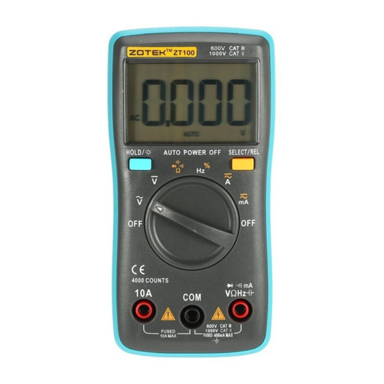
Page 7: Instrument Overview
Instrument Overview LCD Display ③ ④ ⑤ ⑥ ① ② ⑦ ⑮ ⑭ ⑬ ⑫ ⑧ ⑨ ⑩ ⑪ ① Low battery. Replace batteries. ② Display freezes present reading. ③ Continuity test. ④ Diode test. ⑤ Duty cycle test. ⑥ Resistance test. - Page 8 ⑦ Frequency test. (Hertz) ⑧ Capacitance test. (Farad) ⑨ Voltage test. (Volt) ⑩ Current test. (Ampere) Auto range. The product selects ⑪ the range with the best resolution. ⑫ Alternating current. ⑬ Direct current. ⑭ Negative readings. ⑮ Relative mode. Measurement units.
-
Page 9: Function Buttons
Function Buttons ① ② Push once to hold the current reading on the display; push again to continue normal operation. ① Push for more than 2 seconds to turn on the backlight; long-push again to turn off or the backlight automatically turns off after 2 minutes. - Page 10 Selects alternate measurement modes on a rotary switch setting, including: 1. Resistance/Diode/Continuity/Capacitance 2. Frequency/Duty Cycle 3. DC A/AC A 4. DC mA/AC mA ② Push for more than 2 seconds to enter the relative mode. The product will store the present reading as a reference for subsequent readings.
-
Page 11: Rotary Switch
Rotary Switch Turn off the product at this position. • The product automatically powers off after 15 minutes of inactivity. • The built-in beeper beeps 5 times 1 minute before auto power off. • To restart the product from auto power off, press the SELECT botton or turn the rotary switch back to the OFF position and then... - Page 12 Ohms ≤40MΩ Diode test. Displays above 3V Continuity. Beeper turns on at <50Ω Farads ≤200μF Frequency with low voltage Duty Cycle from 1%~99% DC A ≤10A AC A ≤10A DC A ≤400mA AC A ≤400mA...
-
Page 13: Input Terminals
Input Terminals Input terminal AC/DC current measurements to 10A. Common (return) terminal for all measurements. Input terminal for the measurements of: 1. AC/DC voltage 2. Resistance 3. Capacitance VΩHz 4. Frequency 5. Duty cycle 6. Continuity 7. Diode 8. AC/DC current to 400mA... -
Page 14: Measurements Instruction
Measurements Instruction Measure AC/DC Voltage 1. Connect the black test lead to the COM Terminal and the red lead to the VΩHz Terminal. 2. Turn the rotary switch to or to 3. Touch the probes to the correct test points of the circuit to measure the voltage. -
Page 15: Measure Resistance
3. Press SELECT to toggle between AC/DC. 4. Break the circuit path to be measured, connect the test leads across the break and apply power. 5. Read the measured current on the display. *Do not measure current that exceeds the extremes as indicated in the Specifications. -
Page 16: Test For Continuity
*Disconnect circuit power and discharge all capacitors before you test resistance. *Do not input voltage at this setting. Test for Continuity 1. Connect the black test lead to the COM Terminal and the red lead to the VΩHz Terminal. 2. Turn the rotary switch to , press SELECT twice to toggle to the Continuity Mode. -
Page 17: Measure Capacitance
2. Turn the rotary switch to , press SELECT once to toggle to the Diode Mode. 3. Connect the red probe to the anode side and the black probe to the cathode side of the diode being tested. 4. Read the forward bias voltage value on the display. -
Page 18: Measure Frequency
3. Connect the red probe to the anode side and the black probe to the cathode side of the capacitor being tested. 4. Read the measured capacitance value on the display once the reading is stablized. *Disconnect circuit power and discharge capacitors before you test capacitance. -
Page 19: Measure Duty Cycle
Measure Duty Cycle 1. Connect the black test lead to the COM Terminal and the red lead to the VΩHz Terminal. 2. Turn the rotary switch to (applies to high frequency with low voltage), press SELECT once to toggle to the Duty Cycle Mode. 3. -
Page 20: Maintenance
Maintenance Beyond replacing batteries and fuses, do not attempt to repair or service the product unless you are qualified to do so and have the relevant calibration, performance test, service instructions. Clean the Product Wipe the product with a damp cloth and mild detergent. -
Page 21: Replace The Fuses
2. Loosen the screw on the battery door and remove the battery door. 3. Replace the used batteries with new batteries of the same type. 4. Place the battery door back and fasten the screw. Replace the Fuses When a fuse is blown or do not work properly, it shall be replaced as below: 1. -
Page 22: Specifications
Specifications General Specifications 4000 Counts Display(LCD) Ranging Auto Material Update Rate 3 Times/Second × Ture RMS Data Hold √ Backlight √ Low Battery Indication √ Auto Power Off √ Mechanical Specifications Dimension 130*65*32mm Weight 114g (w/o batteries) Battery Type 1.5V AAA Battery * 2 Warranty One year... -
Page 23: Environmental Specifications
Environmental Specifications Temperature 0~40℃ Operating <75% Humidity Temperature -20~60℃ Storage <80% Humidity... -
Page 24: Electrical Specifications
Electrical Specifications Function Range Resolution Accuracy 400.0mV 0.1mV 4.000V 0.001V ±(0.5%+4) DC Voltage 40.00V 0.01V 400.0V 0.1V ±(0.8%+4) 1000V 400.0mV 0.1mV 4.000V 0.001V ±(1.2%+4) AC Voltage 40.00V 0.01V 400.0V 0.1V 750V ±(1.5%+4) 4.000A 0.001A DC Current 10.00A 0.01A ±(1.5%+4) 40.00mA 0.01mA DC Current (mA) - Page 25 Function Range Resolution Accuracy 4.000A 0.001A AC Current 10.00A 0.01A ±(2.0%+4) 40.00mA 0.01mA AC Current (mA) 400.0mA 0.1mA 400.0Ω 0.1Ω 4.000kΩ 0.001kΩ 40.00kΩ 0.01kΩ ±(0.8%+4) Resistance 400.0kΩ 0.1kΩ 4.000MΩ 0.001MΩ 40.00MΩ 0.01MΩ ±(2.0%+4) 4.000nF 0.001nF ±(5.0%+20) 40.00nF 0.01nF 400.0nF 0.1nF Capacitance 4.000μF 0.001μF...
- Page 26 Function Range Resolution Accuracy 99.99Hz 0.01Hz 999.9Hz 0.1Hz 9.999kHz 0.001kHz Frequency ±(0.1%+2) 99.99kHz 0.01kHz 999.9kHz 0.1kHz 9.999MHz 0.001MHz Duty Cycle 1%~99% 0.1% ±(0.1%+2) Diode √ Continuity √...
Need help?
Do you have a question about the ZT100 and is the answer not in the manual?
Questions and answers