Table of Contents
Advertisement
Advertisement
Table of Contents

Subscribe to Our Youtube Channel
Related Manuals for Onlogic HX500

Summary of Contents for Onlogic HX500
- Page 1 HX500 / HX600 Product Manual ...
-
Page 2: Table Of Contents
1.3 Product Specifications 1.4 Exterior Features and Dimensions 1.4.1 - Front I/O 1.4.2 - Back I/O 1.4.3 - Helix 500 Dimensions (HX500) 1.4.4 - Helix 600 Dimensions with PCIe Expansion (HX600) 8 1.5 - System Block Diagram 2 - I/O Definitions 2.1 - Front I/O definition... - Page 3 4.1 - Wake-Up Events 4.2 - Protection Circuitry 5 - Test Reports 5.1 - EN 60601-1-2 Summary 27 5.1.1 - ESD Immunity Data 5.1.2 - Radiated Immunity Data 5.1.3 - Magnetic Immunity Data 27 5.1.4 - Electrical Fast Transient Immunity Data 27 ...
-
Page 4: System Overview
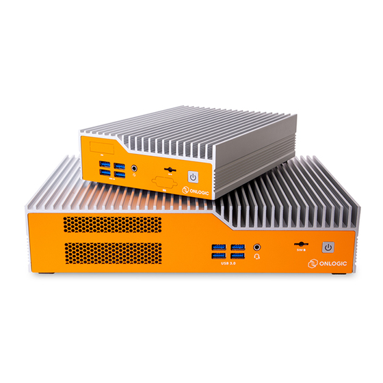
1 - System Overview 1.1 System Introduction The OnLogic Helix series puts Intel® 10th generation Comet Lake processing anywhere you need it. Helix gives you installation flexibility, reliable solid state performance, and unique expandability to help make your next innovation possible. -
Page 5: Product Specifications
1.3 - Product Specifications Model Helix 500 Helix 600 8.26" x 2" x 6.06" 8.26" x 2.55" x 11.9" System Dimensions 210 x 50.8 x 154 mm 210 x 64.8 x 303mm Board Dimensions 8" x 5.5" 8" x 5.5" CPU (on solder side Socket LGA 1200 - Comet Lake S Socket LGA 1200 - Comet Lake S... - Page 6 Voltage Input 8~24V via DC jack or Aux power header 12~24V via DC jack or Aux power header (without GPU) 19~24V via DC jack or Aux power header (with GPU present) 4 Pin Din with optional 4-pin Terminal Block 4 Pin Din with optional 4-pin Terminal Block Power Input (support remote switch, 4 Pin Din covered (support remote switch, 4 Pin Din covered...
-
Page 7: Exterior Features And Dimensions
1.4 - Exterior Features and Dimensions 1.4.1 - Front I/O Note: the HX500 is pictured, the HX600 has the same I/O configuration. 1.4.2 - Back I/O Note: the HX500 is pictured, the HX600 has the same I/O configuration. ... -
Page 8: Helix 500 Dimensions (Hx500)
1.4.3 - Helix 500 Dimensions (HX500) 1.4.4 - Helix 600 Dimensions with PCIe Expansion (HX600) ... -
Page 9: System Block Diagram
1.5 - S ystem Block Diagram ... -
Page 10: I/O Definitions
2 - I/O Definitions 2.1 - Front I/O definition Note: the HX500 is pictured, the HX600 has the same I/O configuration. The location of the DIO option is different for the HX600. Power button / Power LED The front power button can be used to turn on and off the Helix system. The power button is a momentary contact button with a blue LED backlight used to display the status of the system. - Page 11 A pinout is provided below. The audio codec used is a Realtek ALC233. Proper drivers must be installed for both the Q470 chipset and Realtek ALC233 codec. Drivers can be found on the Helix product pages. https://www.onlogic.com/hx500/ https://www.onlogic.com/hx600/ ...
- Page 12 10Gb/s transfer rates. DIO option The Helix platform supports an optional Isolated Digital I/O add-in card (OnLogic ADP102). This option allows for integration of the Helix platform with existing PLC integrations or other digital logic applications. For a complete explanation of features, operating voltages, and safety information, please refer to the DIO expansion manual on the OnLogic support site.
-
Page 13: Rear I/O Definition
2.2 Rear I/O definition The rear I/O of the HX500 is shown below. The HX600 has the same connector orientations and locations on the motherboard. The location of the Terminal block power option is different for the HX600. 4-Pin DIN power connector Mainboard power is applied to the Helix platform by way of a locking 4-pin female DIN connector (Mating part: Kycon #... - Page 14 Function DC - DC - DC + DC + 4-Pin DIN power pinout DisplayPort 1, 2, & 3 Helix utilizes Intel’s Integrated processor graphics that power the onboard DisplayPorts. This means resolutions up to 4096x2304 @ 60Hz are supported on all three outputs simultaneously. All ports support Multi-Stream Transport (MST).
- Page 15 Function Color State LAN link is established Link LAN link is established Green LAN activity Blinking occurring 10 Mb/s data rate 100 Mb/s Speed Green data rate 1000 Mb/s Yellow data rate LAN activity light description USB 3.2 The dual stack USB 3.2 ports on the rear panel are USB 3.2 Gen 2ports, capable of linking at 10Gb/s transfer rates.
- Page 16 Function DC + DC - Terminal block power pinout ...
-
Page 17: Motherboard Connectors
2.3 - Motherboard Connectors The motherboard is the same for HX500 and HX600. M.2 B-Key An M.2 B-Key port is present on the Helix motherboard to allow support for B-Key form-factor expansion cards. Supported cards include 3042, 2242, 2260, 2280 form-factors. The B-Key connector on the Helix platform supports PCIe Gen 3 x2, USB 3.2 5Gb/s, USB 2.0, SATA Gen I (1.5Gbps), SATA... - Page 18 SATA drives can also be created. Refer to the BIOS user manual ( A ppendix C ) for information about using Rapid Storage Technology. A full pinout table for this expansion slot is provided in A ppendix E M.2 E-Key An M.2 E-Key port is present on the Helix motherboard to allow support for E-Key form-factor wireless expansion cards.
- Page 19 COM1 & COM2 The two on-board COM headers utilize standard 9-pin 2.00mm pitch male pin headers with the pin configuration in the chart below. These serial ports support RS-232, RS-422 Full-Duplex, and RS-485 half-Duplex configurations. The serial port communication mode can be selected in the BIOS configuration.
- Page 20 TPM header Helix features an onboard TPM (Trusted Platform Module) header. Helix supports OnLogic’s module (OnLogic part TPM01) featuring TPM 2.0. This gives the option to have a dedicated secure module to secure Helix through cryptographic keys. SATA Data 1 & SATA Data 2 The two on-board SATA Data connectors utilize the standard 7-pin SATA Data latching connector with the standard pin configuration.
- Page 21 (3.0Gbps), and SATA Gen III (6.0Gbps). In addition, they support firmware-level RAID arrays using Intel Rapid Storage Technology. RAID arrays that mix together M.2 SATA and cabled 2.5” SATA drives can also be created. Characteristics of the SATA ports, such as those RAID arrays, can be configured in the BIOS;...
- Page 22 Function Fan header pinout USB 2.0 Header The on-board USB 2.0 header provides a pair of USB 2.0 signals. It utilizes a standard 9-pin 2.54mm pitch male pin connector with the pin configuration in the chart below. The 5V power pins (1 & 2) can provide up to 1A of current.
- Page 23 HDMI interface. The Helix platform supports CEC via the optional add-on module ADP107. For a full description of supported features, refer to the ADP107 product manual located on the Helix platform product pages. https://www.onlogic.com/hx500/ https://www.onlogic.com/hx600/ Power Input Header Mainboard power can be applied to the Helix platform by way of the locking 4-pin Molex Micro-Fit connector (Mating part: Molex #...
- Page 24 Motherboard bottom view (Heatsink side) CPU socket The LGA1200 CPU socket on the Helix platform supports all 10th Gen Intel S-series processors up to 35W TDP PCIe x16 Slot The Helix platform features a standard PCI Express x16 slot on the bottom side that supports PCIe Gen 1 (2.5 GT/s), Gen 2 (5 GT/s), and Gen 3 (8 GT/s).
-
Page 25: Mounting Instructions
The mating substrate must be capable of maintaining the same rating. Step 4 (for DIN Bracket - HX500 only): U sing the outer 2 holes of the 3 hole set on the wall mount bracket, line up the DIN bracket. - Page 26 ...
-
Page 27: Vesa Mounting
3.1 - VESA Mounting Step 1: Attach wall mounting brackets to the chassis using: Screw type: M3X0.5 FH 120 Degree Screw Length: 4 mm Step 2: L ocate the 4 holes that line up accordingly to the bracket as shown Step 3: ... -
Page 28: Power Management
4 - Power Management 4.1 - Wake-Up Events The Helix platform supports multiple power states. The wake-up events can be configured in the BIOS. This section describes the supported power management functions and gives information on protection circuitry for power adapters. ... -
Page 29: Test Reports
5 - Test Reports 5.1 - EN 60601-1-2 Summary The Helix platform complies with the EN 55032:2015 standards for radiated and conducted emissions limits.. The unit is compliant with EN 55035:2016 and tailored by EN 60601-1-2 for ESD, radiated immunity, magnetic immunity, electrical fast transient (EFT) AC power line, dips/interrupts and EFT signal line immunity based on performance criteria in Tables 4, 5, 6, 7, 8, and 9. -
Page 30: Dips/Interrupts Immunity Data
The system does not exhibit susceptibility 0.5-kV/1-kV electrical fast transients, delivered in 5-kHz bursts to signal lines. The Helix platform was unaffected during testing. 5.1.5 Dips/Interrupts Immunity Data Dips/interrupts immunity tests were performed following EN 55035 and EN 60601-1-2 in accordance with EN 61000-4-11. -
Page 31: Appendices
GPUs are limited to 19V-24V input. Only 24V is tested for Configuration 3). *The configurations below are using representative samples of internal devices, the specific components mentioned below may vary from the devices provided by OnLogic. System Config 1 Low... - Page 32 The power consumption for each system configuration is record below Config 1 Low Power Consumption 12V (W) 24V (W) Windows Idle CPU / system Stress 33.6 35.4 CPU / System & 41.1 41.5 Graphics Stress 1.14 1.42 0.97 1.18 Deep S5 0.28 0.43 Config 2 Mid...
-
Page 33: Appendix B: Isolated Dio Guide
6.3 - Appendix C: BIOS manual For a detailed overview of the BIOS screens and individual settings, please refer to the OnLogic support site. Instructions for updating the BIOS can also be found on the support site. Please refer to the link below for detailed instructions. -
Page 34: Appendix D: System Thermal Results
10% of the rated base clock. No CPU or GPU throttling was observed during testing of both the HX500 and HX600 at the maximum rated temperature, with some configurations running above the base clock frequency. - Page 35 HX500 - Thermal Testing Results Table - t he table below shows the key i 9 10900T (10C @1.90GHz) takeaway values from the above test HX600 - GPU Validation Thermal Testing Graph - T he image below shows the thermal test results ...
- Page 36 HX600 - GPU Validation Thermal Testing Results Table - t he table below shows the key takeaway values from the above test. ...
-
Page 37: Appendix E: Expansion Port Pinout
6.5 - Appendix E: Expansion port pinout 6.5.1 - M.2 B-Key Function Function CONFIG_3 3.3V 3.3V FULL_CARD_POWER_OFF# USB 2.0 D+ W_DISABLE1# USB 2.0 D- CONFIG_0 GPIO_10/W_DISABLE2# PERn1/USB3.1-Rx- UIM-RESET PERp1/USB3.1-Rx+ UIM_CLK UIM_DATA PETn1/USB3.1-Tx- UIM_PWR PETp1/USB3.1-Tx+ PERn0/SATA-B+ PERp0/SATA-B- PETn0/SATA-A- PETp0/SATA-A+ PERST# CLKREQ# REFCLKn PEWAKE# REFCLKp... -
Page 38: M.2 E-Key
SIM_DETECT RESET_N SUSCLK CONFIG_1 3.3V 3.3V 3.3V CONFIG_2 6.5.2 - M.2 E-Key Function Function 3.3 V USB_D+ 3.3 V USB_D- PCM_CLK RESERVED CNV_RF_RESET#_R RESERVED BT_PCMIN BT_PCMOUT RESERVED RESERVED RESERVED RESERVED RESERVED RESERVED RESERVED PETp0 RESERVED PETn0 RESERVED RESERVED PERp0 RESERVED PERn0 RESERVED RESERVED... -
Page 39: M.2 M-Key
PERST0# CLKREQ0# W_DISABLE2# PEWAKE0# W_DISABLE1# RESERVED RESERVED RESERVED RESERVED RESERVED RESERVED 3.3V RESERVED 3.3V 6.5.3 - M.2 M-Key Function Function 3.3 V 3.3 V PERn3 PERp3 DAS/DSS (I/O)/LED_1# (I)(0/3.3V) PETn3 3.3 V PETp3 3.3 V 3.3 V PERn2 3.3 V PERp2 PETn2 PETp2... -
Page 40: Mpcie
SMB_CLK (I/O)(0/1.8V) PERn0/SATA-B+ SMB_DATA (I/O) (0/1.8V) PERp0/SATA-B- ALERT# (I) (0/1.8V) PETn0/SATA-A- PETp0/SATA-A+ PERST# (O)(0/3.3V) or NC CLKREQ# (I/O)(0/3.3V) or NC REFCLKn PEWAKE# (I/O)(0/3.3V) or NC REFCLKp CONNECTOR Key M CONNECTOR Key M CONNECTOR Key M CONNECTOR Key M CONNECTOR Key M CONNECTOR Key M CONNECTOR Key M CONNECTOR Key M... -
Page 41: Appendix F: Safety Information
PERp0 1.5V SMB_CLK PETn0 SMB_DATA PETp0 USB 2.0_D- USB 2.0_D+ 3.3V 3.3V 1.5V W_DISABLE2# 3.3V 6.6 Appendix F: Safety Information Do not open or modify the device. The device uses components that comply with FCC and CE regulations. Modification of the device may void these certifications. 6.6.1 Safe use and installation instructions 1. -
Page 42: Précautions Et Guide D'installation
16. Only use UL Listed connectors for 17. Service and repair of the device must be done by qualified service personnel. This includes, but is not limited to, replacement of the CMOS battery. Replacement CMOS battery must be of the same type as the original. 18.
Need help?
Do you have a question about the HX500 and is the answer not in the manual?
Questions and answers