
Related Manuals for K&M Burkhard Reuter RLA4G

Summary of Contents for K&M Burkhard Reuter RLA4G
- Page 1 Specifications and Operator Manual of antenna RLA4G Version: 1.3 Created: 20.06.2020 Konstruktion & Musterbau Burkhard Reuter Ziegelstraße 54 06862 Dessau-Roßlau...
- Page 2 IP65 (with connected loops and connection cable) Compliance: CE according to DIN EN 55013, EN 55020, EN 60065 RoHS / WEEE Directive, ear-Reg. 27676700 All specifications are subject to design changes! K & M Burkhard Reuter EDITION DATE NAME Page RLA4G 03/08/20 B. Reuter...
-
Page 3: Safety Precautions
Never dispose of the appliance elsewhere, such as household waste. It pollutes our environment! The nameplate of the RLA4G is located inside the amplifier housing. It is visible after removing the base plate. - Page 4 (the zeros are approximately in the axial direction of the socket). This direction also corresponds to the 0° setting on the control unit. The RLA4G is not suitable for direction finding. The absolute deviation of the setting compared to the actual reception direction can be several 10°s.
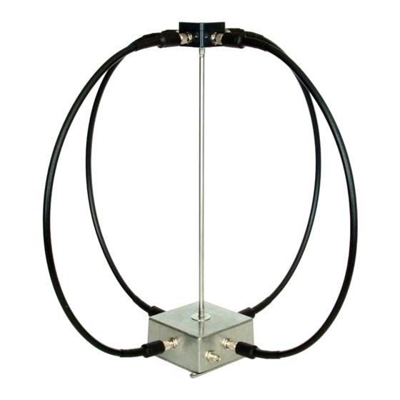
- Page 5 Assembly of the antenna RLA4G The RLA4G is supplied with disassembled antenna elements. Component set for an antenna RLA4G The component set consists of the following parts: • 4 pieces of antenna elements (each half of a loop), coaxial cable LMR-400 with TNC connectors of reversed polarity (RP-TNC).
- Page 6 K & M Burkhard Reuter EDITION DATE NAME Page RLA4G 03/08/20 B. Reuter...
- Page 7 The most sensible approach with the RLA4G is to first slightly screw on the cables to the upper connection housing and let them hang straight down near the sockets on the amplifier housing. Then plug them in as described and screw them on completely.
Need help?
Do you have a question about the RLA4G and is the answer not in the manual?
Questions and answers