
Summary of Contents for Barnstead International Imperial III 1464 Series
- Page 1 Imperial III General Purpose Incubators Series 1464, 1465, 1466 Model No. Gravity Convection: 302, 302-1 305, 305-1 310, 310-1 Mechanical Convection: 305M, 305M-1 310M, 310M-1 LT1465X3 • 3/14/06...
-
Page 2: Table Of Contents
Table of Contents Description ................................3 Safety Information ..............................4 Alert Signals..............................4 Specifications ..............................5 Electrical Requirements..........................5 Temperature Range ............................5 Shipping Weight............................5 Unit Dimensions............................5 Environmental Conditions ..........................6 Unpacking and Installation ..........................7 Shipping Carton ............................7 Location ................................7 Leveling ................................7 Shelf Installation ............................7 Operation ................................9 Control Panel ..............................9 Start-Up ................................9 Setting Operating Temperature Thermostat ....................10... -
Page 3: Description
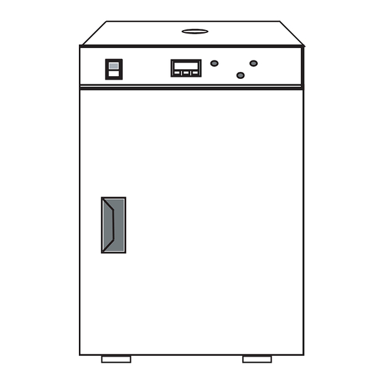
Description Barnstead|Lab-Line Imperial III General Purpose Incubators are useful in all types of general incubating and paraffin imbedding. Cabinets are made of heavy-gauge steel with a powder- coated finish for optimum appearance and easy cleaning, while the interior walls are stainless steel to spread warm- wall radiant heat evenly throughout the chamber. -
Page 4: Safety Information
Safety Information Your Barnstead|Lab-Line Imperial III General Purpose Alert Signals Incubator has been designed with function, reliability, and safety in mind. It is your responsibility to install it in con- formance with local electrical codes. It is most important Warning that the user follow installation instructions exactly as writ- Warnings alert you to a possibility of ten. -
Page 5: Specifications
Specifications Electrical Requirements Voltage Hertz Amps Watts 50/60 302-1 50/60 50/60 (1 electrical outlet, 120V, 500W total load) 305M 50/60 (1 electrical outlet, 120V, 500W total load) 305-1 50/60 (1 electrical outlet, 120V, 500W total load) 305M-1 50/60 (1 electrical outlet, 120V, 500W total load) 50/60 (1 electrical outlet, 120V, 500W total load) 310M... -
Page 6: Environmental Conditions
PECIFICATIONS Environmental Conditions Operating: 15°C to 40°C; 20% to 80% relative humidity, non-condensing. Installation category II (overvoltage) in accordance with IEC 664. Pollution degree 2 in accordance with IEC 664. Altitude Limit: 2,000 meters. Storage: -25°C to 65°C 10% to 85% relative humidity... -
Page 7: Unpacking And Installation
Unpacking and Installation Shipping Carton The shipping carton should be inspected upon delivery. When received, carefully examine for any shipping dam- age before unpacking. If damage is discovered, the deliv- ering carrier should both specify and sign for the damage on your copy of the delivery receipt. - Page 8 NPACKING AND NSTALLATION Repeat this procedure for the opposing bracket making sure it is on the same level as the first bracket (count the slots). Install other shelf brackets in the same way then slide shelves into place.
-
Page 9: Operation
Operation Control Panel POWER SWITCH: This 2-position rocker switch controls power to entire unit. The switch is lit when power is ON. Warning Do not use in the presence of flam- CONTROL STATUS LAMP: This lamp is lit when mable or combustible materials or power is being supplied to heater and not lit explosive gases. -
Page 10: Setting Operating Temperature Thermostat
PERATION Setting the Over-Temperature Thermostat After the unit has reached set point, rotate the over-tem- perature thermostat stem counterclockwise until the over- temperature status lamp (4) is lit. Then rotate it clockwise approximately 5 degrees past the point at which the lamp is no longer lit. -
Page 11: Auto Tune
PERATION SET POINT ADJUSTMENTS: The temperature controller normally displays the chamber tem- perature. To view or change the temperature set point proceed as follows: Press Controller ✳ View setpoint ✳▼ Decrease setpoint ✳▲ Increase setpoint Press and hold the “STAR” (✳) key and use either the UP or DOWN arrow key to adjust the set point to the desired temperature. -
Page 12: Temperature Calibration
PERATION The controller display should now be alternating between tunE and oFF. Press and hold the “STAR” (✳) key. Press and release the up arrow key until At.SP is dis- played. Release the “STAR” (✳) key. After one minute has elapsed, the controller dis- play will begin to alternate between showing the chamber temperature, tunE and At.SP. - Page 13 PERATION Using the examples shown below and the ther- mometer value obtained in the previous step, enter the correct Zero value into the controller by pressing the “STAR” (✳) key and using the UP or DOWN arrow key. If there is already a Zero value present then add the new value to the one already present.
-
Page 14: Troubleshooting
Troubleshooting The following is intended as a guide to help in servicing this unit, if problems should occur. Note Before attempting any repair, discon- nect power cord from outlet. Note A qualified controls service techni- cian must perform maintenance and repairs. -
Page 15: Maintenance
Maintenance Checking Controls Warning Disconnect from the power supply • While using the unit, occasionally check that both prior to maintenance and servicing. control panel status lamps are functioning as described in the previous OPERATION section. Warning • During normal operation, with controls properly set, Refer servicing to qualified personnel. -
Page 16: Stainless Guidelines
AINTENANCE stainless its characteristic “stainless” quality. Also expo- sure of the surface to other oxidizing environments can produce a passivating film or coating. However, if free oxygen is not available due to scale or contamination buildup the metal surface may become vul- nerable to rusting and corrosion as well as pitting. -
Page 17: Special Considerations
AINTENANCE Special Considerations WARNING: If it is necessary to use the following chemi- cals, limit exposure time to a maximum of 3 hours. Always clean surfaces immediately after use. Aluminum chloride E.D.T.A. Potassium permanganate Barium chloride Ferrous chloride Potassium thiocyanate Calcium chloride Lysol Sodium hypochlorite... -
Page 18: Materials Effective In Disinfecting
MINIMAL scrubbing. Always follow cleanings with a clean water rinse. Air dry. Note This information is intended as guide- Materials Effective in Disinfecting lines only and Barnstead International makes no claim as to the suitability to • Glutaraldehyde any particular situation. Consult your staff chemist to determine what would •... -
Page 19: Servicing Guide
Servicing Guide Heater Replacement Warning Heaters are not replaceable. Call Barnstead International Disconnect from the power supply Customer Service at 1-800-553-0039 for assistance. prior to maintenance and servicing. Warning Thermostat Replacement Refer servicing to qualified personnel. After unplugging the unit, remove the top cover of the unit to reach control components. -
Page 20: Replacing Temperature Controller
ERVICING UIDE Replacing Temperature Controller Place ON/OFF switch in OFF position. Unplug incubator from outlet power supply. To remove controller from control housing: a) Use both hands to firmly grip each side of the controller bezel. b) Press on the bezel side grips until the bezel tabs release. -
Page 21: Replacement Parts
Replacement Parts DESCRIPTION PART NUMBER Fan Blade, M Series: 160-136-00 Cordset: 470-105-00 Gasket, Body: Models 302 Series: 530-186-00 Models 305 Series: 530-182-00 Models 310, 310-1(2): 530-182-00 Gasket, Outer Door: Models 302 Series: 530-185-00 Models 305 Series: 530-181-00 Models 310, 310-1(2): 530-181-00 Inner Door, Tempered Glass: Model 302:... -
Page 22: Wiring Diagram
Wiring Diagrams AMBER LAMP RED LAMP CONTROLLER NOT USED ON MODEL 310 ONLY CHAMBER ELEMENTS MODEL NUMBERS DESCRIPTION REF. 302M 305M 310M RESETABLE FUSE ------------- ------------- 330-119-00 330-119-00 330-119-00 RESETABLE FUSE 330-118-00 330-118-00 330-118-00 POWER SWITCH 440-359-00 440-359-00 440-359-00 440-359-00 440-359-00 FAN MOTOR -------------... - Page 23 IRING IAGRAMS AMBER LAMP RED LAMP CONTROLLER NOT USED ON MODEL 302-1 MODEL 310-1 ONLY MODEL NUMBERS REF. DESCRIPTION 302-1 302M-1 305-1 305M-1 310-1 310M-1 RESETABLE FUSE 330-118-00 330-118-00 330-118-00 330-118-00 330-118-00 330-118-00 RESETABLE FUSE 330-118-00 330-118-00 330-118-00 330-118-00 330-118-00 RESETABLE FUSE 330-125-00 330-125-00...
-
Page 24: Ordering Procedures
All parts listed herein may be ordered from the Barnstead International dealer from whom you pur- chased this unit or can be obtained promptly from the factory. When service or replacement parts are needed we ask that you check first with your dealer. -
Page 25: Decontamination Statement
Decontamination Statement We cannot accept any product or component sent to Barnstead International for repair or credit that is contaminat- ed with or has been exposed to potentially infectious agents or radioactive materials. No product or component will be accepted without a "Return... -
Page 28: Two Year Limited Warranty
SALE, USE OR PERFORMANCE OF ANY PRODUCTS, WHETHER SUCH CLAIM IS BASED ON CON- TRACT, TORT (INCLUDING NEGLIGENCE), ANY THEORY OF STRICT LIABILITY OR REGULATORY ACTION. The name of the authorized Barnstead International dealer nearest you may be obtained by calling 1-800-446-6060 (563-556-2241) or writing to: 2555 Kerper Boulevard...
Need help?
Do you have a question about the Imperial III 1464 Series and is the answer not in the manual?
Questions and answers