
Summary of Contents for Teletek electronics TP2000
- Page 1 TP2000 TransmiTTer PaLm Programmer installation and Operation manual This manual is intended for authorized personnel installing TP2000 transmitters on perimeters. It does not refer to the end user of the unit.
- Page 2 GUaranTee During the guarantee period the manufacturer shall, at its sole discretion, replace or repair any defective product when it is returned to the factory. All parts replaced and/or repaired shall be covered for the remainder of the original guarantee, or for ninety (90) days, whichever period is longer.
-
Page 3: Table Of Contents
1. GENERAL DESCRIPTION OF TP2000 V.7.X TRANSMITTER .......4 1.1 Calculating the Length of the TP2000 Transmitter Antenna ........5 1.2 Installing TP2000 Transmitter .................5 1.3 Added Functions in the Software Revision 7.X of TP2000 Transmitter ....6 2. INTRODUCTION TO TP2000 INTEGRATOR ............6 2.1 Transmitter Programming Procedures..............7 2.2 Main Screen of Programming Kit for TP2001 v.6.5 Transmitters ......7... -
Page 4: Tp2000 Transmitter
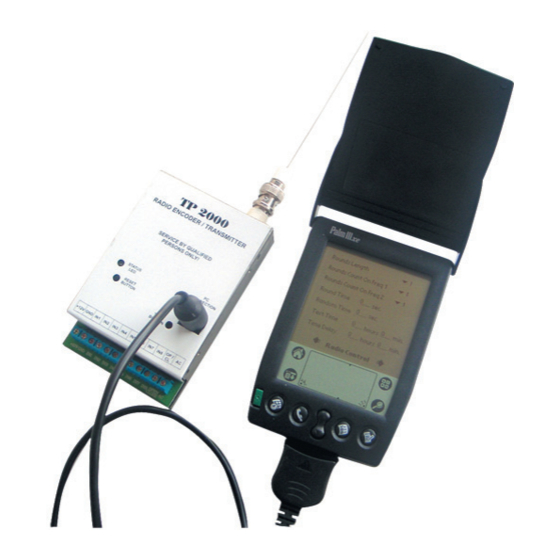
• Compact design. 1. General Description of TP2000 V.7.X Transmitter TP2000 V.7.X Transmitter consists of a printed circuit board placed in a metal box. It comprises two modules - a digital one, located in the lower part of the printed circuit board, and a high-frequency module in its upper portion. -
Page 5: Calculating The Length Of The Tp2000 Transmitter Antenna
• TP2000 integrator program; • a PS2-to-RS cable. You need to have installed the TP2000 integrator program on your computer. To do this you have to run the seTUP command from the floppy disc you have been provided with by the vendor. On the successful completion of installation the icon of TP2000... -
Page 6: Added Functions In The Software Revision 7.X Of Tp2000 Transmitter
The added functions cause a change of the TP2000 transmitter parameters programming software - TP2000 integrator. The button advanced Properties is moved in the screen inputs, see page 13. The other changes in the TP2000 integrator software are explained together with the added functions of the TP2000 Transmitter. -
Page 7: Transmitter Programming Procedures
Default command from the Bar menu. Open the required file and press the Program XXX button. Choose TP2000 ver.6.5.X and this will invoke the Programming Kit for TP2001 v.6.5 Transmitters program which will enable you to store the required settings in the transmitter. -
Page 8: Bar Menu
TP2000 Transmitter Installation and Operation Manual In the main screen of Programming Kit for TP2001 v.6.5 Transmitters program are to be found: • Bar menu with commands for uploading data from a transmitter or a file, storing settings in a transmitter or in a file, accessing a file with instructions on using the program and exiting the application;... -
Page 9: Radio Tab
Before pressing this button make sure you have stored the modifications you have made by selecting the Write to Transmitter command. Note: If you are using Programming Kit for TP2000 V.6.X Transmitter you will find and a Help button in the bar menu. -
Page 10: Identification Group
TP2000 Transmitter Installation and Operation Manual 2.2.2.2 Identification Group In the Identification field group, see Figure 6, you set up the identity of the transmitter within the perimeter. Figure 6. The Identification group. The address, system and Group fields set up the parameters by which the transmitter is to be identified. - Page 11 That could be specified in the Advanced Properties screen, see Figure 11, page 15. The transmitting can be stopped from the installer – with restoring of the signal at the transmitter input or after manual pressing of the Test button on the TP2000.
-
Page 12: Deviation Field
TP2000 Transmitter Installation and Operation Manual 2.2.2.4 Deviation Field The Deviation field, see Figure 8, has to correspond to the central station settings. Press and select one of the options available in the combo-box. 0, 1, 2, 3, 4, 5, 6 or 7. -
Page 13: Inputs Tab
TP2000 Transmitter Installation and Operation Manual Inputs Tab 2.2.3 Next to the radio tab you will find the inputs tab, see Figure 9, that controls the values on the transmitter’s inputs. Figure 9. The inputs Tab. Defining the parameters on the Transmitter inputs. - Page 14 TP2000 Transmitter Installation and Operation Manual Colour indication: • red - inactive; • green - active; • grey - status impossible. To change an event status left-click an indicator. Placing the cursor of the mouse on the soft button of an input allows visualization of its connection scheme in the lower left corner of the window.
-
Page 15: Advanced Properties Screen
TP2000 Transmitter Installation and Operation Manual 2.2.3.1 Advanced Properties Screen Press button in the inputs tab to access the additional fine settings advanced Properties screen, see Figures 11 and 12. The advanced Properties screen is divided into three groups of fields: •... - Page 16 TP2000 Transmitter Installation and Operation Manual With choosing the Logical reloc. you can direct the events to one of the two frequencies as desired. The type of the events that you can direct to a relevant frequency are as follows: •...
-
Page 17: Serial Connection With Ca60Plus Alarm System For Transmitting Of Zone Information
Connect the green interface cable of the Ca60Plus control panel to the AC input of the TP2000 Transmitter. Thus you will make a serial connection between them – see also Figure 14. Figure 14. - Page 18 The establishing of serial connection between TP2000 Transmitter and CA60Plus Control panel is automatic after you power up the transmitter or single pressing of the reseT button of TP2000. You must also check the field CA62 Serial Connection in the Inputs screen, see Figure 15.
-
Page 19: Test Mode Tab
• PGm1 - duplicates the state of output PGM1 of СА60Plus control panel. The messages for loss or recovery of main power supply and these for the battery status are automatically generated and transmitted of the TP2000 Transmitter. A Trouble message will be automatically transmitted to the monitoring station if the serial connection between TP2000 and CA60Plus has been interrupted. - Page 20 TP2000 Transmitter Installation and Operation Manual Figure 16. The Test mode Tab. At first all indicators will glow in dark green. This means that the inputs are inactive, i.e. no signal has been sent out. The colour indication of the last four indicators is to be understood as follows: •...
-
Page 21: Com Tab
Select COm Tab to specify the COM port to which your transmitter is connected, see Figure 17. In TP2000 COm Port group select the radio button corresponding to the port to which you have connected your transmitter by means of the PS2-to-Canon9 cable you have been provided with. -
Page 22: Status Bar
TP2000 Transmitter Installation and Operation Manual 2.2.6 Status Bar The status Bar of the Programming Kit for TP2001 v.6.5 Transmitters window will display the inventory and serial number of the transmitter that has been selected to be programmed. Both numbers are set at the time of manufacture and are read from the transmitter when the read from Transmitter command is executed. - Page 23 PaLm PrOGrammaTOr OPeraTiOn manUaL...
-
Page 24: Palm Programmer
The main menu can also be turned on from the aPPLiCaTiOn icon. 1. introduction to the PaLm PrOGrammaTOr for TP2000 Regularly observe the battery charge level. The installed programme will be deleted if it is not changed in time. -
Page 25: Transmitter Programming Operations
PaLm Programmator Operation Manual 2. Transmitter Programming Operations The programme is allocated onto various screens which can be scrolled through with the on both sides of the message of the screen or by the main help of the arrows button itself, which can be used to access a random screen. The desired parameters (settings) can be selected from the cascading windows and marked in check-boxes or can be introduced with the help of the character/digital keyboard. -
Page 26: Load/Save" Button
PaLm Programmator Operation Manual 3.1 “Load/Save” Button Use this button to save or view a transmitter parameter adjustment file. After setting the adjustment changes, a new file can be created or changes to an already existing file can be saved. Select the desired file (or create a new one) from the window that opens and then press the button for the operation, required to be performed: Load /save /Delete/ Close. - Page 27 The TP2000 v.7.X Transmitter supports three protocols: Electronics Line, LARS and LARS1. Press and select the name of the required protocol in the Protocol check- box.
-
Page 28: Radio Control" Screen
PaLm Programmator Operation Manual 5. “radio Control” screen Figure 22. radio Control screen of PaLm Programmator Set the Radio Control parameters in this group. The Deviation check-box must correspond to the monitoring station parameters. Press and select any of the options offered in the combination box - 0, 1, 2, 3, 4, 5, 6 or 7. Every space corresponds to 500 Hz. -
Page 29: Inputs" Screen
PaLm Programmator Operation Manual In the Tx On Time check-box enter the warming-up time for setting a stable carrier frequency prior to transmission. The value entered must be within the interval of 0.1 to 5.0 sec. over a spacing of 0.1 sec. In the reset Time check-box select the warming-up time for setting the transmitter after power up following which the transmitter begins to transmit. -
Page 30: Misc Inputs" Screen
PaLm Programmator Operation Manual If one transmitter is to be used for two sites, the sites can respectively be set the values of addr 1 and addr 2 and for each one a connection can be established with the respective logical channels. -
Page 31: Advanced 1" Screen
PaLm Programmator Operation Manual 8. “advanced 1” screen Figure 25. advanced 1 screen of PaLm Programmator. The advanced 1 screen is divided into two groups of check-boxes: • sensitivity; • rna (“Transmission of non-restored alarms”). Set the sensitivity of each transmitter input in the sensitivity group. Press select any of the offered options - 0,1;... -
Page 32: Advanced 2" Screen
PaLm Programmator Operation Manual 9. “advanced 2.” screen Figure 26. advanced 2 screen of PaLm Programmator. The “advanced 2” Screen provides for the reallocation of events between one of the two transmission frequencies. Tick one or both check-boxes for any event depending on whether the desired signal for the relevant event should be transmitted by Frequency 1, Frequency 2 or by both frequencies simultaneously*. - Page 33 PaLm Programmator Operation Manual eXamPLe 1: If events are to be transmitted through physical inputs in1, in2 and in3 over the two frequencies, the Physical relo. check-box must be turned on, along with the three in1, in2 and in3 check-boxes - Figure 27. Figure 27.
-
Page 34: Permissible Intervals For The Parameter Values
PaLm Programmator Operation Manual 10. Permissible intervals for the Parameter Values If an incorrect value is introduced in any of the check-boxes, the programme shall either correct it to its maximum extent or shall reject it. For example, in the “round Time” check-box, in the radioControl screen, the permissible values should be within the interval between 0 and 127. - Page 35 nOTes...
- Page 36 Distributor: www.teletek-electronics.com Address: 14A Srebarna Str., 1407 Sofia, Bulgaria tel.: (+359 2) 9694 700, fax: (+359 2) 962 52 13 e-mail: info@teletek-electronics.bg...
Need help?
Do you have a question about the TP2000 and is the answer not in the manual?
Questions and answers