
Summary of Contents for ANK L5
- Page 1 L5 Signature Phono Stage Construction Manual Version 3.00, October 2019 audionotekits@rogers.com 1-613-822-7188...
-
Page 2: Table Of Contents
Table of Contents Section 1 — Introduction ……………………………………………..………………………….…………….……… About ANK Audio Kits ……………………………………………..………………………….……………..……… Basic Operation of the Phono Stage ……………………………………………………..……...……… 1.2.1 Overview ………………………………….……………………………………………..……..……… 1.2.2 Specifications ……………....…………………….……..………………………………...……… 1.2.3 Design Elements …………………………………………………………….……..……..……… Equipment ……………………………..…………………………………………………………………….….……. 1.3.1 Overview of the Kit ……………………………………………………….………….…….…..…… Tips and Suggestions …………………………………………………….………….……………………..….……... - Page 3 Section 3 —Chokes Installation …………………………..…....….……………..…..……....…. Overview …………….…………………………………………………………………………..….………..…….…… Installing the Chokes …………….……………………..….………………………………………………..…….…… Section 4 — Power Supply Board Installation ……………..…………………..…..……....…. Overview ………………………………………………………………………………………..…………..…………… 33 Installing the Valve Base ……………………………………………………………..…………..…………… 33 Installing the Valve Base ……………………………………………………………..…………..…………… 34 Installing the Shield …………………………....………………………………..……………………..…… 35 Section 5 — Super Regulator Board Installation ……………………..…..……....….
- Page 4 Section 9 — Testing ……………………………………………………………….…………………………….. Overview …………….…………………………………………………………………………………………………… 64 Installing the Fuse …………….……………………………………………………………………………………… 65 Initial Tests …………….…………………………………………………………………………………………………… 66 First Power-Up …………….………………………………........………………………………………… 66 Voltage Check …………….…………………………………….…………………..........…… 67 Sound Check …………….………………………………..........…….……………………… 67 Section 10 — Finishing Touches ……………………..………………………….……….…………….…...………… 68 10.1 Installing the Front Faceplate ………..………………………………………..…….………………………………...
-
Page 5: Section 1 - Introduction
Thanks for purchasing the ANK Audio Kits L5 Signature Phono Stage. This Phono Stage represents a stunning addition to our L5 product line and we believe it is truly one of the finest phono stages on the planet! And our goal is to provide you with the highest quality kit that you will build from scratch with these instructions. -
Page 6: About Ank Audio Kits
As a result, ANK Audio Kits began offering this service for some Level 4 and 5 products so that a significant investment in a kit could be turned into a work of art! Since ANK Audio Kits was born in 2004, over 2,500 kits have been shipped to customers worldwide. Clearly, there is a real demand for high end audio kits and ANK Audio Kits has been delivering the goods now for 15 years. -
Page 7: Basic Operation Of The Phono Stage
ANKits is pleased to announce the new L5 Signature Phono Stage. Who doesn't love listening to the magic of a vinyl record? The development of the L5 Signature Phono Stage started in earnest to aim for the ultimate phono stage utilizing the NOS 5U4G rectifier tube. The new L5 Signature Phono Stage joins our Mentor Pre-amplifier and DAC 5.1 making what we are calling the 'Triple Threat'. -
Page 8: Design Elements
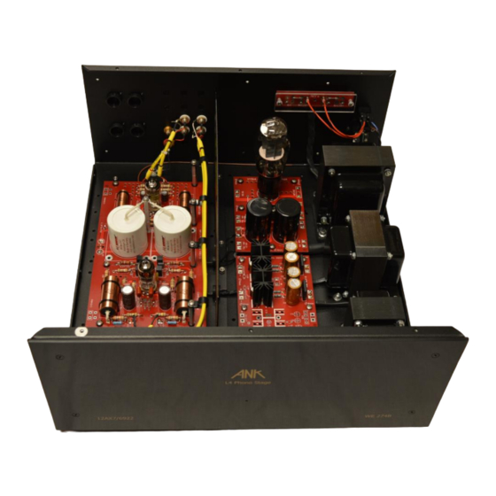
1.2.3 Design Elements Power Supply Board The goal was to start with the ultimate Power Supply to provide superior dynamics, detail, and an ultra black background. Based on the Mentor Pre-amplifier power supply technology, it incorporates a shunt design with two unique 4-pole Chokes, a pair of 4-pole MLytic Power Supply capacitors and Audio Note (UK) Kaisei electrolytics. -
Page 9: Equipment
Equipment Here is the list of equipment that will be required: Philips screwdriver A pair of quality wire strippers A large, organized work area Soldering iron station with wet sponge Lead-based solder (4% Silver is recommended) 1.3.1 Overview of the Kit In your kit you will find a series of kit bags containing all the hardware, wire, and parts for the... -
Page 10: Components
That way of looking at things sometimes now no longer applies. Please be assured that all resistors supplied with ANK Audio Kits are rated at least per the specified wattage: in some cases, a higher than specified wattage may be supplied. -
Page 11: Diodes
1.4.6 Diodes match the stripe on the diode with When installing diodes note that they are oriented with a stripe — the banding (||) stencil on the board. 1.4.7 Hardware/Mechanical Not all of us are mechanically oriented. So, the kit is well laid out such that all the hardware is provided and bagged in individual sections, so things should make sense. -
Page 12: Wire Color
1.4.10 Optional Finishing Touches From time to time we get asked about some of the build details of the ANK Finished Products that you can see in the pictures in the "Assembled Kits Gallery!" (https://ankits.smugmug.com/) on our website. -
Page 13: Organization Of This Manual
9. Testing 10. Finishing Touches 11. Final Thoughts Appendix This manual is an early version. Please provide any feedback to ANK Audio Kits via phone or email (audionotekits@rogers.com) at any stage of the build. Copyright © 2019 AudioNote Kits www.AudioNoteKits.com Page 13 audionotekits@rogers.com... -
Page 14: Electrical Safety Warning
There are sufficient voltages in this kit to give you a very nasty and harmful shock, so be very careful when powering on, debugging, and probing around. Please contact ANK Audio Kits via phone or email (audionotekits@rogers.com) to discuss any precautions necessary when building the kit if you feel unsure about what you are doing at any stage of the build. -
Page 15: Section 2 - Mechanical Assembly And Initial Mains Transformer Wiring
Section 2 Mechanical Assembly and Initial Mains Transformer Wiring In this section we will install the feet, IEC socket, Rocker Switch, and the IEC board. Before we begin, It's a good idea when you receive the kit to do a complete inventory. You should see the following parts: ... -
Page 16: Overview
Overview Here's our goal in this section: Copyright © 2019 AudioNote Kits www.AudioNoteKits.com Page 16 audionotekits@rogers.com... -
Page 17: Installing The Feet
Installing the Feet Let's start by installing the feet on the chassis — this will make it easier to work with as we install the transformers, Choke, etc. Turn the chassis upside down. Take a foot and insert an M4 screw with washer into it — it might be tight but just push it in. Install each foot in the hole in the chassis closest to the corner and secure it with an M4 nut on the inside of the chassis. - Page 18 When completed your feet will look like the picture below. You're on your way! Copyright © 2019 AudioNote Kits www.AudioNoteKits.com Page 18 audionotekits@rogers.com...
-
Page 19: Installing The Rocker Switch And Iec
Installing the IEC Socket and Rocker Switch Take the IEC socket and install it in position as shown below, with the fuse holder on top and the GND lug on the bottom. Use M3 10mm CSK flat head screws and nuts to secure it. Have a look at the picture below: Note the orientation of the Rocker Switch with the smaller pair of tabs towards the side of the chassis and the larger pair towards the middle. -
Page 20: Installing The Chassis Ground Screw
Installing the Chassis Ground Screw Insert the M4 16mm Chassis Ground screw (from underneath) into the unpainted position near the corner of the chassis, as shown below: Copyright © 2019 AudioNote Kits www.AudioNoteKits.com Page 20 audionotekits@rogers.com... -
Page 21: Installing The Mains Transformer
Installing the Mains Transformer We'll begin by installing the rubber strips: Install the rubber strips on the chassis where the PLPT-A Mains transformer will go. Next, have a look at the picture below and position the Mains transformer in the chassis such that the two White, two Black, and the one Green wires go towards the back of the chassis. -
Page 22: Preparing The Mains Ground Wire
Preparing the Mains Ground Wire Now let's prepare the Mains (Green) Ground wire. The Mains transformer has a Green wire coming out of it — this is a ground wire that attaches to the Chassis Ground screw on the chassis. We'll trim this wire to the proper length; then we'll strip the end of the wire and tin it. - Page 23 Here's a picture of the completed Mains Ground wire: We'll attach it to the chassis a bit later. Copyright © 2019 AudioNote Kits www.AudioNoteKits.com Page 23 audionotekits@rogers.com...
-
Page 24: Iec Board Wiring
IEC Board Wiring Now we'll wire the IEC board, which will make the remaining wiring from the Rocker Switch to the Mains transformer much easier to implement. Before we do so, have a look at what we want to accomplish: After you've read through the steps that follow, if you are in any doubt as to the IEC/Rocker Switch/IEC board wiring, please contact audionotekits@rogers.com Note that there are 4 pads with 4 solder tabs each. - Page 25 Wiring for 120V Operation Cut the four wires (White, White/Grey, Black, and Black/Grey) coming out of the Mains Primary to the lengths you'll need to reach the IEC board when it's situated on the rear of the chassis, as Note: you can connect the wires from the top or the underside of the board, as you shown above.
- Page 26 Add the two jumpers as shown. (You can use some left over Black Primary wire or bare wire, as you prefer.) Copyright © 2019 AudioNote Kits www.AudioNoteKits.com Page 26 audionotekits@rogers.com...
- Page 27 Referencing the diagram below, complete the IEC/Rocker Switch wiring as shown. Regarding the aesthetics, you have several options: 1. Solder the Red and Black wires from the Rocker Switch to the front of the board (see picture above). You can use either of the unused holes on each tab. 2.
-
Page 28: Connecting And Mounting The Iec Board
Connecting and Mounting the IEC Board Again, referencing the diagrams on the previous page, Push the crimped ends of the Red and Black wires coming from the IEC board onto the left (wider spaced) lugs of the Rocker Switch, Red on top, Black below. Apply the pressure necessary to position the wires correctly onto the lugs. -
Page 29: Chassis Ground Connections
Chassis Ground Connections Finally, let's make two Chassis Ground connections. Retrieve the Green Mains Ground wire and the Green IEC Ground wire and, using a nut, loosely secure the two grounds to the Chassis Ground Screw, as shown below. Take the prepared 10R Ground cable and attach it as well to the Chassis Ground screw. (We'll attach the other end to the Phono board later.) Copyright ©... -
Page 30: Installing The Rca Jacks
2.10 Installing the RCA Jacks Next, we'll install the RCA jacks for the input and output to the Phono Stage. For each RCA jack, Insert into the chassis — from the outside, in the following order: The white insulating washer with the raised ring facing inwards into the hole ... - Page 31 Time for a break! Copyright © 2019 AudioNote Kits www.AudioNoteKits.com Page 31 audionotekits@rogers.com...
-
Page 32: Section 3 -Chokes Installation
Chokes Installation Overview The heart of the L5 Signature Phono Stage is a very sophisticated Power Supply with a large Mains transformer (PLPT-A) along with two substantial 4-pole Chokes (DCH01 and DCH02). In this section we'll install the 2 4-pole Chokes. A Choke is an inductor that is used to smooth the Power Supply voltage. -
Page 33: Section 4 - Power Supply Board Installation
Section 4 Power Supply Board Installation Overview Here's a view of the Power Supply board, showing the 5U4G rectifier tube placement and the 2 4-pole capacitors. Copyright © 2019 AudioNote Kits www.AudioNoteKits.com Page 33 audionotekits@rogers.com... -
Page 34: Installing The Valve Base
Installing the Valve Base We'll begin by installing the 8-pin valve base for the 5U4G rectifier. The key is to make sure the Use masking tape to secure the valve base to the board prior to soldering. valve base is level : if you have a base that is soldered in on an angle then your tube will lean over! Solder from the underside of the board. -
Page 35: Installing The Shield
Shield Installation On the underneath of the shield, locate the hole that has no paint on it — this will match up with a hole on the chassis that is also unpainted in order to ensure a good grounding of the shield when installed in the chassis. -
Page 36: Section 5 - Super Regulator Board Installation
Section 5 Super Regulator Board Installation Overview Here's a picture of the completed board in the chassis: This board takes the AC from the Mains transformer and supplies the 6.3V AC for the filaments for the Phono board. It uses "super quiet" 5-pin regulators. Some pictures show a section that is not used. -
Page 37: Parts List
Parts List Quantity Designation Description Part Number B1, B3 Bridge Rectifier GBU4M-BPMS-MD C1, C2, C7, C8 4700uf 25v cap 604-1058-nd Heat Sink FA-T220-25E IC1, IC3 Regulator LT1963AE R5, R1 A105957CT-ND R6, R2 PPC14.0KXCT-ND C5, C9 47uf 604-1054-ND on heat sink HS pads 926-1475-nd Installing the PCB Resistors... - Page 38 Be sure to solder on the underside of the board and check that you have nice little “volcanoes” on each solder joint. (While it's not necessary, you can solder these through hole resistors on the top as well. If you hold the heat when soldering on the bottom for an extra 1/2 second or so, usually just enough solder will flow through so that it forms a nice volcano on the top without the need to touch it up.) When you clip a lead be sure to clip above the volcano so you don’t slice off the nice joint.
-
Page 39: Installing The Capacitors
3. Touch the other end to a distant point that is directly connected (i.e., with no additional resistance) to the other end of the resistor. (You'll may have to flip the PCB over and back to determine where to position the lead.) You'll be able to read the value of that resistor and . -
Page 40: Installing The Bridge Rectifiers
Installing the Bridge Rectifiers Quantity Designation Description Part Number B1, B3 Bridge Rectifier GBU4M-BPMS-MD A Bridge Rectifier accepts an AC voltage and generates a DC voltage which, in the Phono Stage, is used as the filament voltage. You'll see a notch on the Bridge Rectifiers (part number: GBU4M): match the notch with the '+' (POSITIVE) stencil on the board. -
Page 41: Installing The Regulators
Installing the Regulators Quantity Designation Description Part Number IC1, IC3 Regulator LT1963AE First, let's have a look at how a regulator is attached to a heatsink. Take an M3 PAN head screw and mount a regulator on a heatsink as shown above. The heatsink is the same front and back. -
Page 42: Installing The Shunt Resistor
Installing the Shunt Resistor Next we will install the 10K 50W Gold Shunt Resistor into the chassis. There are holes pre drilled in the chassis at the front of the chassis in front of regulator board. Preparing the LED Installation Refer to the LED installation package to install the LED wiring on the Super regulator board. -
Page 43: Section 6 - Power Supply Interwiring
Section 6 Power Supply Interwiring The information needed to complete the Power Supply interwiring is contained in the PDF file "Power Supply Interwiring." As appropriate in the this section and in the later interwiring, route wires through the grommet in a way that makes the most sense in terms of neat routing. - Page 44 Copyright © 2019 AudioNote Kits www.AudioNoteKits.com Page 44 audionotekits@rogers.com...
- Page 45 Copyright © 2019 AudioNote Kits www.AudioNoteKits.com Page 45 audionotekits@rogers.com...
- Page 46 Copyright © 2019 AudioNote Kits www.AudioNoteKits.com Page 46 audionotekits@rogers.com...
- Page 47 Copyright © 2019 AudioNote Kits www.AudioNoteKits.com Page 47 audionotekits@rogers.com...
- Page 48 Copyright © 2019 AudioNote Kits www.AudioNoteKits.com Page 48 audionotekits@rogers.com...
- Page 49 Copyright © 2019 AudioNote Kits www.AudioNoteKits.com Page 49 audionotekits@rogers.com...
- Page 50 Copyright © 2019 AudioNote Kits www.AudioNoteKits.com Page 50 audionotekits@rogers.com...
- Page 51 At this point we suggest you just solder the twisted Red and Black wires to the Super Regulator board and later we will connect to them the Phono board. For now, leave them quite long. Well done if all that is done! You've completed the wiring of the Power Supply. Congratulations! Copyright ©...
-
Page 52: Section 7 - Phono Board Installation
Section 7 Phono Board Installation Overview Let's look at the other side of the chassis. The Power Supply provides the High Tension (HT) voltage to the Phono board, along with the 2 filament voltages; that’s a lot of building just for those 3 things! The circuit uses a 12AX7 input tube and a 6922 output stage;... -
Page 53: Parts List
Parts List Here is the parts list for the Phono board: Quantity Value Other Tubes 6922 12ax7 Valve Bases 9-pin CMC valve base Resistors 47K Takman non magnetic 1K Takman non magnetic 1K2 Takman non magnetic 100K Takman non magnetic 68R Takman non magnetic ½W 15K Takman non magnetic... -
Page 54: Installing The Resistors
Installing the Resistors Let's begin by installing the resistors: Quantity Value Wattage 47K Takman non magnetic 1K Takman non magnetic 1K2 Takman non magnetic 100K Takman non magnetic 68R Takman non magnetic ½W 15K Takman non magnetic 39K (39K2) Takman non magnetic 33K Takman non magnetic 470R Takman non magnetic 1M Takman non magnetic... -
Page 55: Installing The Valve Bases
As you can see in the picture on the previous page, the values of the components are printed right on the board, so we suggest you take the resistors in the Phono board parts bag and use a ohmmeter to measure each value. - Page 56 And, finally, Install the 2 big White 47uf Mundorf EVO Oil film capacitors, as shown below. They are film capacitors so there is no polarity, but we suggest you install them with the writing as shown. These capacitors are connected between the High Tension (HT) voltage and Ground. The capacitors goes into the board and then are soldered on the underside of the board: the lead on the top now must be connected to a specific ground point on the PCB, as shown in the picture on the next page.
- Page 57 As shown below, Take a wire and extend it from the capacitor lead, using a ground lug on the end (this should be prepared and part of your kit; if not it'd easy to make one). The correct orientation of the grounding connections. Take 2 M4 screws and nuts and connect the ground lugs to the correct locations, as shown.: Copyright ©...
-
Page 58: Section 8 - Interwiring
Section 8 Interwiring Overview With the Phono board completed let's tackle the interwiring between the Phono board and the input and output shielded wiring, along with the Power Supply and the Super Regulator boards and the Chassis Ground. Interwiring Copyright © 2019 AudioNote Kits www.AudioNoteKits.com Page 58 audionotekits@rogers.com... - Page 59 Let's look at each section of the interwiring, with all the completed boards. Referencing the graphic on the previous page, Use 18g Red PTFE (Teflon-coated) wire to connect the B+ on the Power Supply board to the HT (+) on the Phono board. Similarly, use 18g Black PTFE wire to connect the B- on the Power Supply board to the –...
- Page 60 These are the two filament holes used for the 6922 output tube. Copyright © 2019 AudioNote Kits www.AudioNoteKits.com Page 60 audionotekits@rogers.com...
-
Page 61: Connecting The Third Chassis Ground Wire
Connecting the Third Chassis Ground Wire With the filaments connected and the HT/Ground connected we need to look at two more areas: the first would be the Chassis Ground wire with resistor and capacitor attached — this is the prepared wire with a ground lug that we connected earlier to the Chassis Ground Screw (near the Mains transformer). -
Page 62: Connecting The Shielded Audio Note (Uk) An-A Input And Output Cables
Connecting the Shielded Audio Note (UK) AN-A Input and Output Cables The AN-A cable is basically a shielded cable with a Ground sheaf around it and two Signal conductors, Red and White. We've prepared the cable: the Red lead is the Signal and the White lead is tied to the Ground sheaf. - Page 63 On the output side you will do the same; these connections are marked O/P and COM, as shown below: Copyright © 2019 AudioNote Kits www.AudioNoteKits.com Page 63 audionotekits@rogers.com...
-
Page 64: Section 9 - Testing
Section 9 Testing Overview It's time do to some testing to make sure that the Phono Stage has been correctly wired and that things are working the way they're supposed to. Our plan is as follows: With no tubes installed, power the Phono Stage on to verify that the fuse does not blow. ... -
Page 65: Installing The Fuse
Before testing, it's a good idea to blow some air into the unit to make sure that there are no small pieces of wire or solder floating around. Installing the Fuse Tubes Installed At This Point: None Let's start by installing a 1A Slo-Blo fuse from the IEC bag. -
Page 66: Initial Tests
Initial Tests Let's begin by doing some basic tests, with the Phono Stage off. A good place to start is to measure resistance. Let's have a look at the Chassis Ground, an important (almost) universal ground point in the Phono Stage. Try this: ... -
Page 67: Voltage Check
(or, in our real world case, the DC voltages) settle. If this checks out, congratulations! You should have a working L5 Signature Phono Stage. Feel free to contact us to share your excitement. -
Page 68: Section 10 - Finishing Touches
Section 10 Finishing Touches 10.1 Installing the Front Faceplate Remove the protective films from the front and back of the front faceplate. Install the front faceplate using four Black M4 CSK flat head screws. 10.2 Installing the LED Carefully trim the LED leads so that they are not exposed. Glue or attach (with some Blu Tack) the LED holder to the front panel so that the LED protrudes through the designated hole, as shown below: 10.3 Last Looks Inside... -
Page 69: Section 11 - Final Thoughts
11.3 Tube Rolling We feel that the sound of the ANK Audio Kits L5 Signature Phono Stage is truly sublime. It provides a highly detailed and transparent presentation with gorgeous sonics. Rolling some quality new production tubes and/or some nice NOS tubes in the 12AX7, 6922, and 5U4G positions will allow you to tailor the sound to your particular preferences. -
Page 70: 12Ax7
11.3.2 6922 The sound of the ANK Audio Kits DAC 2.1 Signature is very highly regarded and it is one of our most popular kits. It provides a detailed and transparent presentation with gorgeous sonics. Rolling some nice NOS tubes will allow you to tailor the sound to your particular preferences. -
Page 71: Thanks
11.4 Thanks Thank you for investing in the ANK Audio Kits L5 Signature Phono Stage and congratulations on working your way through the build. Please email us at audionotekits@rogers.com and let us know how everything went: were there any errors in the manual or instructions, parts lists, etc.? Your ideas regarding greater clarity or tweaks will also be truly appreciated. -
Page 72: Appendix
Appendix Copyright © 2019 AudioNote Kits www.AudioNoteKits.com Page 72 audionotekits@rogers.com... -
Page 73: Resistor Color Code Reference
You can also find an 'Interactive Resistor Color Code Calculator' on our website (available from the Links page). Copyright © 2019 AudioNote Kits www.AudioNoteKits.com Page 73 audionotekits@rogers.com... -
Page 74: Wiring For 240V
Wiring for 240V Operation This section describes how to wire the IEC PCB for 240V. Before we do so, have a look at what we want to accomplish: Cut the four wires (White, White/Grey, Black, and Black/Grey) coming out of the Mains Primary Note: to the lengths you'll need to reach the IEC PCB when it's situated on the rear of the chassis. - Page 75 Connect these four Primary wires to the IEC PCB, as shown in the diagram below. Cut off the excess wire. Add the jumper as shown below. (You can use the left over end of the Black Primary wire or a bare wire, as you prefer.) Copyright ©...
- Page 76 Referencing the diagram below, complete the IEC/Rocker Switch wiring as shown. Regarding the aesthetics, you have several options: 1. Solder the Red and Black wires from the Rocker Switch to the front of the board (see picture above). You can use either of the unused holes on each tab. 2.
Need help?
Do you have a question about the L5 and is the answer not in the manual?
Questions and answers