Advertisement
Quick Links
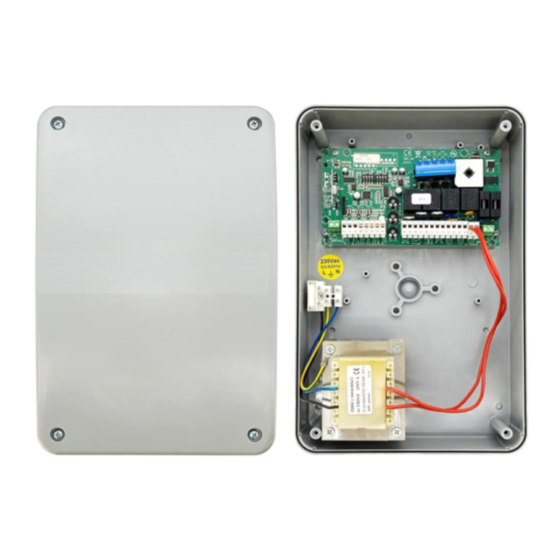
INSTALLATION OF THE CONTROL PANEL CR/41
WHERE PLACING THE CONTROL PANEL
Place the device near the gate, in order to have the minimum lenght of the cables for connection with the system.
We suggest to place the control panel under a cover or in a place with two lateral walls, to protect it against the
weather conditions. Moreover fix it at 1,5m height so to be far from children.
The control panel is supplied from factory with the opening towards the left side. It is possible to change the opening,
please follow the below instructions:
COVER OPENING: TOWARDS THE RIGHT SIDE
Insert a screwdriver in the hole for the hinge-fixing which is in
the front side of the cover and pull the hinge pressing the
"tooth" (picture 2)
Pag. 1/10
S
E
Fig.1
R
A
GATE OPENERS DEPARTMENT
ATTENTION: This operation has to be made before the
!
fixing on the wall.
Insert a screwdriver in the hole for the hinges-fixing in the
back side (as shown in the picture) and pull the cover,
pressing the fixing "tooth" (picture 1)
Fig.2
Install the hinges on the right side of the back cover,
insert them with the fixing "tooth" towards the indoor
part of the cover until the click (picture 3)
Fig.3
I
Advertisement

Related Manuals for Serai CR/41

Summary of Contents for Serai CR/41
- Page 1 GATE OPENERS DEPARTMENT INSTALLATION OF THE CONTROL PANEL CR/41 WHERE PLACING THE CONTROL PANEL Place the device near the gate, in order to have the minimum lenght of the cables for connection with the system. We suggest to place the control panel under a cover or in a place with two lateral walls, to protect it against the weather conditions.
- Page 2 WALL FIXING OF THE CONTROL PANEL aaaaaa aaaaaa We suggest to install the device near the gate, in order to have the minimum lenght of the cables for the Ø 6 ÷ 8 mm connection with the whole system. aaaaaa The control panel has to be fixed with the holes for the passing of the cables downwards aaaaaa...
-
Page 3: Connection Diagram
), for lamps without 11 - 12 FLASHING LIGHT F1 = 2A 250V~ the inside electronic - for ex. SERAI RZ/20F - ACCESSORIES 24V- 12 - 13 Output for courtesy lamp (230Vac- ): switched-on for 90 sec. after the STOP... - Page 4 The setting of the motor force is made by changing the voltage through the trimmer “Power” in the control panel CR/41. The installation has to be carried out in the full respect of the current Laws concerning the gate automaton.
-
Page 5: Dip Switch Setup
DIP-SWITCH SET-UP ATTENTION: The set-up of the dip-switches has to be made with no power-supply to the control panel. When the control panel is switched on, the set-up is confirmed and activated. We suggest, after the dip-switch set-up, to program the working time (see Control panel programming). - Page 6 DIP-SWITCH FUNCTION DESCRIPTION SET-UP SW 1 SW 2 - A start impulse during the opening is not considered. A start impulse during the pause with the gate opened closes the gate. start " " - A start impulse during the closig stops the gate for 2 sec. and STE-BY-STEP opens it automatically.
-
Page 7: Control Panel Programming
CONTROL PANEL PROGRAMMING Before proceeding with the programming it is necessary to control that all electrical and safety devices are connected (push-button, photocells, flashing light, etc...) Check their correct functionning and if necessary: All LED for the NC entries must be (stop, photocells etc...) All LED for the entries NO must be (start, pedestrian) - Page 8 PROGRAMMING OF THE WORKING TIME AND THE SLOW-DOWN FOR GATE WITH ONLY ONE WING (DIP1 SW1 ON) Control panel ON, gate closed. Press one time the button A (SET) to enter into programming. LED DL10 starts flashing. The programming phase begins. Press one time push-button C (WORK): the motor M1 starts the opening.
- Page 9 LEARNING OF TRANSMITTER CODE The control panel has an incorporated two-channel receiver at 433,92 Mhz which allows to remotely drive the gate through transmitters at dip-switches - OG/02 and OG/04 - and also self-learning transmitters OG/62, OG/64, OG/52, OG/54, OG/82/1 and OG/84. The first channel of the receiver works like a start, while the second channel works like “pedestrian”...
- Page 10 OUTPUT 1st CHANNEL: ALTRO DL10 START COMMAND PEDESTRIAN OF THE spia CONTROL PANEL COMMAND 2324 ON CR/41 -CLAMPS 1-2- 2526 POWER LAMPS BREAK WORK ANTENNA PED START STOP FOTO FOTO AP FINE CH FINE AP OTHER AUTOMATIC ELECTRIC LOCK...
Need help?
Do you have a question about the CR/41 and is the answer not in the manual?
Questions and answers