
Summary of Contents for Side-Power MIDI201
- Page 1 Windlass Systems Side-Power MIDI201 Installation and user manual SLEIPNER MOTOR AS P.O. Box 519 N-1612 Fredrikstad Norway www.side-power.com Document id: 2904 Revision: © Sleipner Motor AS 2019...
-
Page 2: Table Of Contents
Content Introduction of Midi series....................................3 User guide..........................................4 Before installation......................................6 Dimensions........................................7 Installation .........................................8 Mounting Midi........................................8 Insert the rope into the line wheel .................................9 Rope around the line wheel ..................................10 Minimum clearance and height under the windlass ..........................11 Installation of stop ring for auto stop ................................. 12 Wiring diagram.......................................13 Electrical installation ..................................... -
Page 3: Introduction Of Midi Series
Side-Power Engbo MIDI 201 is designed for boats up to approximately 25 feet. These windlasses are true free-fall windlasses and are developed with a new electrical control box unit. This new unit is ready for connecting Side-Power remote control and switch panel. -
Page 4: User Guide
User guide Docking with remote control RC-21E, RC-22E & RC-23E Make sure the boat engine is running during anchoring. Decide where you want to drop anchor. Check that the safety line on the anchor has been loosened. Turn ON the main switch of the windlass. When main switch for the windlass has been switched off, you must press down both ON buttons on the remote, be- fore pressing DOWN button to release the anchor. - Page 5 User guide Wireless remote control RC-21E The remote is waterproof and floats if dropped into the water. It has under normal conditions an radio range of 15m. See own manual for more information and variants. Note! Remote and receiver is normally connected and ready to use.
-
Page 6: Before Installation
It will often be necessary to install a hull conduit with a roller that guides the rope with low friction through the hull. Rope Side-Power Engbo supplies original woven anchor rope with a lead core . It is supplied in various lengths and dimensions. Safety line Once the anchor is seated in the anchor bracket, it must be secured with the safety line supplied. -
Page 7: Dimensions
Dimensions Midi 201 2904-6 - 2019... -
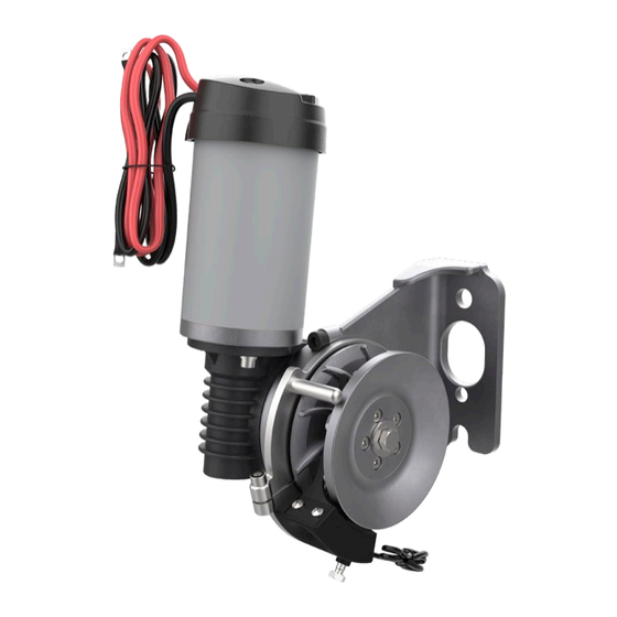
Page 8: Installation
Installation Mounting • The mounting bracket for MIDI 201 allows for infinitely vari- able rotation in relation to the windlass gear/motor. • The bracket for the rope guide/deflector can also be rotated independently of the gear/motor and mounting bracket. • This allows for installing the windlass on surfaces with dif- ferent angles in relation to the stern. -
Page 9: Insert The Rope Into The Line Wheel
Insert the rope into the windlass line wheel Insert the rope into the line wheel between the line wheel and the rope guide. It may be easier if you bend the tip of the rope guide carefully. Route the rope via the line wheel and out through the hole in the rope deflector. -
Page 10: Rope Around The Line Wheel
Installation Rope around the line wheel The mounting bracket for MIDI 201 allows for infinitely variable rotation in relation to the windlass gear/motor. The bracket for the rope guide/deflector can also be rotated inde- pendently of the gear/motor and mounting bracket. See separate description. -
Page 11: Minimum Clearance And Height Under The Windlass
Installation Minimum rope clearance and height under windlass In order for the windlass to function normally, there must be a sufficient volume/height below the windlass for stowing the rope when the anchor is up. This table below shows recommended minimum height (A) below the windlass as well as width (B) and length (C) of the area used for stowing the rope. -
Page 12: Installation Of Stop Ring For Auto Stop
Installation The enclosed steel rings (auto stop rings) are fitted in the loca- tions where the windlass should slow down and then come to a full stop. Mark in advance; see procedure on the previous page. Open the stop rings with the keeper ring plier. Fit the ring over the rope. -
Page 13: Wiring Diagram
Wiring diagram Positioned for easy access. Must be turned OFF when Control unit not in use! ... -
Page 14: Electrical Installation
1 pcs switch panel • Cables are optinal and come in various lengths. • Cable is a 4-way Side-Power cable that easy can be attached to contact on controlbox unit. • The cable must be attached to 150810 contact unit... -
Page 15: Installation Of Control Unit 150800
Electrical installation Fitting control unit 150800 The unit is not water resiststant and must be placed in a dry area close to the windlass motor. Use ring termianls of good quality with the correct size for the selected battery cables. Bolt hole shuld be 6mm. Tighten the teminals to maximum 5Nm. -
Page 16: Main Switch/Miniature Circuit Breaker
Electrical installation Main switch/miniature circuit breaker 119-00015(Midi 100-150A) • MUST be used at all time in this installation • Works as both MCB and main switch unit. • The unit consists of one battery connection and one AUX connection. This is described on the unit. See wiring diagram for correct connection to to battery and contriol box. -
Page 17: Maintenance And Service
Maintenance and service Winter storage • Remove the rope from the windlass before every period of winter storage. Soak it in a mild soap solution overnight. Then wash it in water and rinsing fluid to rinse out all the salt resi- due and dirt. -
Page 18: Technical Data
Weight: windlass with motor and cables 9,8kg Weight: electronic unit aprox 1kg Auto stop function Recommended anchor/ weight 7.5-16 kg Bruce, plate or Side-Power Recommended boat size Max. 7.6 m (25 feet) Fitting/mounting See the separate descriptions for the individual models Standard equipment... -
Page 19: Troubleshooting
Troubleshooting Note! Main switch/braker must be disconnected whenever working on the windlass mechanical parts FAULT SYMPTOM FAULT CODES/STATUS SOLUTION Windlass does not operate "Power" LED not lit Check: Main switch/breaker is engaged. Check battery fuses. Visually inspect cables and verify that terminals are tight. Measure battery voltage. - Page 20 Operations and functions Midi 201 2904-6 - 2019...
- Page 21 Midi 201 2904-6 - 2019...
- Page 22 Midi 201 2904-6 - 2019...
- Page 23 Midi 201 2904-6 - 2019...
- Page 24 Worldwide sales and service www.side-power.com SLEIPNER MOTOR AS P.O. Box 519 N-1612 Fredrikstad Norway The information given in the document was correct at the time it was published. However, Sleipner Motor AS can not accept liability for any inaccuracies or omissions it may contain.
Need help?
Do you have a question about the MIDI201 and is the answer not in the manual?
Questions and answers