Advertisement
Advertisement

Summary of Contents for DR Power Grader
- Page 1 ® POWER GRADER SAFETY & OPERATING INSTRUCTIONS DR Power Equipment Toll-free phone: 1-800-DR-OWNER (376-9637) Serial No. Fax: 1-802-877-1213 Original Language Order No. Website: www.DRpower.com Read and understand this manual and all instructions before operating the DR POWER GRADER.
-
Page 2: Table Of Contents
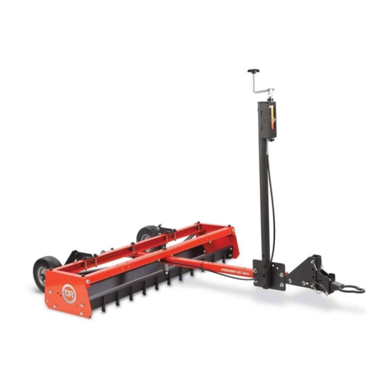
Additional Information and Potential Changes Figure 1 DR Power Equipment reserves the right to discontinue, change, and improve its products at any time without notice or obligation to the purchaser. The descriptions and specifications contained in this manual were in effect at printing. -
Page 3: Chapter 1: General Safety Rules
Labels Your DR POWER GRADER carries prominent labels as reminders for its proper and safe use. Shown below are copies of all the Safety and Information labels that appear on the equipment. Take a moment to study them and make a note of their location on your POWER GRADER as you set up and before you operate the unit. - Page 4 Never allow people who are unfamiliar with these instructions to use the DR Power Grader. To be safe, do not operate the grader near small children or pets, and never allow children to operate the Power Grader. Stop the grading action when another person or pet approaches.
- Page 5 No list of warnings and cautions can be all-inclusive. If situations occur that are not covered by this manual, the operator must apply common sense and operate this DR POWER GRADER in a safe manner. Contact us at www.DRpower.com or call 1-800-DR- OWNER (376-9637) for assistance.
-
Page 6: Chapter 2: Setting Up The Dr Power Grader
Chapter 2: Setting Up the DR POWER GRADER It may be helpful to familiarize yourself with the controls and features of your DR POWER GRADER as shown in Figure 1 before beginning these procedures. If you have any questions at all, please feel free to contact us at www.DRpower.com. - Page 7 Specifications Teeth 12-Tungsten Carbide-Tipped 4142 Hardened Alloy Steel Mold Board Cold Rolled 1018 Steel 3-Gauge (.2391") Wheels Flat free- Solid Rubber, 8"X3.00"-4"/2.25" Hitch Height Range 3.63" to 13.922" Tooth length below frame rails .8" Number of revolutions to raise teeth 1" in Weight capacity (blocks) 80lbs (2 standard 16"x8"x8"...
- Page 8 Bolt Head and one under The Locknut. The only Bolts that don’t use a Flat Washer under the head is the Shoulder Bolts. Figure 7 Locate a clean flat surface to assemble the Power Grader. Position the Frame Assembly with the front facing up to gain access to the Tooth Bar Tooth Bar area (Figure 7).
- Page 9 Turn the Tooth Bar around so the teeth are facing forward (Figure 9). Secure the Tooth bar with the four Bolts, eight Flat Washers and Locknuts but only hand tight for now. Flip the Frame Assembly over so the front of the Frame Assembly is facing forward and both Crossmembers are on top (Figure 10).
- Page 10 Note: Hold the Handle upright as you tighten the Nut against the Control Box hex. Post U-Bolts and Locknuts Figure 15 Crank Post Two Holes Crank Bolt, Lock Facing Handle Washer and Forward Flat Washer Nuts Sliding U-Bolt Backing Plate Bolts and Height Adjust Locknuts Control Box Figure 17 Figure 16 ® POWER GRADER...
- Page 11 Secure the back side of the two Axle Brackets to the rear Crossmember with Bolts, Rail Spacers and Locknuts two 3/8-16X 3/4" Bolts (with Washers) and Locknuts (with Washers) using a Ratchet, Extension and 9/16" Socket on the inside and a 9/16" Wrench on the inside (Figure 18).
- Page 12 Front Bushing Jam Nut Slot Figure 23 Cable Eyelet Cable Spring Bracket Snap Safety Pin Figure 24 Rear Jam Nut Tow Bar Front Jam Nut Cable Tie Height Adjust Rubber Cable Cable Bushing Figure 26 Figure 25 ® POWER GRADER...
- Page 13 Lift the Tow Bar and position the Tow Hook Hitch over the Hitch Ball on Plate the ATV (Figure 30). Pull back on the Power Grader so the slot in the Tow Bar Keyhole Hitch fits around the Hitch Ball Shaft.
- Page 14 Crank Post Adjustment The Crank Post can be adjusted to fit the Lawn Tractor or All Terrain Vehicle you will be using to tow the Power Grader. The Post can be moved forward or back on the Tow Bar as needed so the operator has easy access and no part of the Tow Vehicle will contact the Grader while turning.
-
Page 15: Chapter 3: Operating The Dr Power Grader
Do not use these types of vehicles; the DR POWER GRADER is difficult to see. NEVER operate the DR POWER GRADER with a Truck (2WD or 4WD). Use of a Truck will void the DR POWER GRADER Warranty. CONTACT US AT www.DRpower.com... - Page 16 Avoid filling Pot Holes filled with water, wait until the holes are dry. Use the DR POWER GRADER to work the edges of Pot Holes that are more than 4 feet wide to loosen the sides before you begin filling them.
- Page 17 Adjusting the Power Grader for Grading and Scarifying Crank Knob Rotate the Crank Knob counterclockwise until the Slider is at the bottom of the scale to lower the machine and take all of the weight off the Wheels (Figure 33).
- Page 18 Crossmembers to prevent them from being bounced off the machine. Lowering the Wheels for transporting Rotate the Handle clockwise to raise the Slider to the top of the scale (Figure 42). This will lower the Wheels and lift the Power Grader off the ground for transporting. Figure 40...
- Page 19 Drag Screen is ideal for areas that have high sand or soil content such as new lawns, riding rinks, ball fields, or sandy driveways. The Drag Screen is also very helpful in seeding large areas. By lifting the Scarifying Teeth and Mold Board of the DR POWER GRADER above the working surface so that only the wheels make contact, the Drag Screen simply and effectively distributes the topsoil uniformly over the seed.
-
Page 20: Chapter 4: Maintaining The Dr Power Grader
Lubricate Wheels as needed Cleaning the Power Grader Use a Hose or Pressure Washer to clean the DR POWER GRADER to keep the Scarifying Teeth Plate, Wheels etc. clean and clear of debris. Checking the Shear Pin Check the Shear Pin for signs of wear or damage. Replace the Shear Pin if worn or damaged. -
Page 21: Chapter 5: Troubleshooting
Most problems are easy to fix. Consult the Troubleshooting Table below for common problems and their solutions. If you continue to experience problems, contact us at www.DRpower.com or call toll-free 1-800-DR-OWNER (376-9637) for support. Before performing any maintenance, you must first shut off the tow vehicle, remove the key and set the parking brake. -
Page 22: Chapter 6: Parts Lists, Schematic Diagrams And Warranty
Hardware, we will send Flanged Bolts and Locknuts (Flat Washers not required) as shown in the following illustrations. Parts List – GRADER BOX ASSEMBLY Note: Part numbers listed are available through DR Power Equipment. Ref# Part# Description Ref# Part#... - Page 23 Schematic – GRADER BOX ASSEMBLY CONTACT US AT www.DRpower.com...
- Page 24 Parts List – TOW BAR ASSEMBLY Note: Part numbers listed are available through DR Power Equipment. Ref# Part# Description Ref# Part# Description 37235 Bracket, Hitch Adjustment 37236 Lanyard, Hair Pin 36676 Assembly, Hitch, Pin 37237 Pin, Shear, 1/2" 33333 Nut, Nylon Lock, Flanged, 3/8-16...
- Page 25 Schematic – TOW BAR ASSEMBLY CONTACT US AT www.DRpower.com...
- Page 26 Parts List – CONTROL BOX ASSEMBLY Note: Part numbers listed are available through DR Power Equipment. Ref# Part# Description Ref# Part# Description 366561 10-24 X 1/4" Slotted Head, Steel 366961 1/2-8, Nut, Coupling, Acme 366931 Clamp, Collar, Shaft, 1/2" 366911...
- Page 27 Parts Schematic – CONTROL BOX ASSEMBLY CONTACT US AT www.DRpower.com...
- Page 28 Parts List and Schematic – DR POWER GRADER Optional Drag Screen (Kit No. 210861) Note: Part numbers listed are available through DR Power Equipment. Ref# Part# Description 210861 Drag Screen, 48", w/Chain and Links 230991 Snap, Spring, 5/16" 211751 Connector, Threaded...
- Page 29 Notes: CONTACT US AT www.DRpower.com...
- Page 30 Notes: ® POWER GRADER...
- Page 31 The DR POWER GRADER is warranted for two (2) years against defects in materials or workmanship when put to ordinary and normal consumer use; ninety (90) days for any other use. For the purposes of all the above warranties, “ordinary and normal consumer use” refers to non-commercial residential use and does not include misuse, accidents or damage due to inadequate maintenance.
- Page 32 Wipe down the DR POWER GRADER to remove any moisture and dirt that may have accumulated. If possible, store the Power Grader in a dry, protected place. If it is necessary to store the Power Grader outside, cover it with a protective material.
Need help?
Do you have a question about the Power Grader and is the answer not in the manual?
Questions and answers