
Subscribe to Our Youtube Channel
Related Manuals for JST AP-F6

Summary of Contents for JST AP-F6
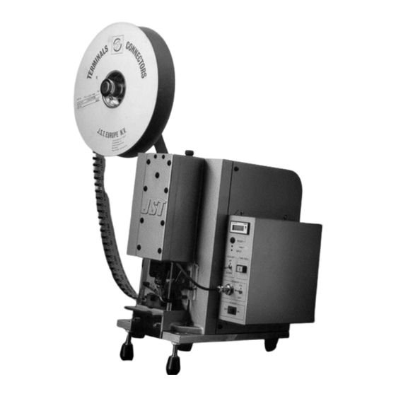
- Page 1 AP-F6 PNEUMATIC TAPE-ON-REEL CRIMPING MACHINE OPERATION MANUAL V:\Mark\AP-F6 Operation Manual.doc...
- Page 2 T.O.R (Tape-on Reel) terminals. Before using the AP-F6, please read this manual to ensure that you are familiar with the features of the machine and the layout of the operating controls.
-
Page 3: Table Of Contents
AP-F6 PNEUMATIC CRIMPING MACHINE Table of Contents 1. SPECIFICATIONS……………………………………………………………………… 1 - 1 Crimping Machine Specifications……………………………………………… 1 - 2 Crimping dies…………………………………………………………………….. 2. INSTALLING AND TRANSPORTING THE MACHINE…………………………….. 2 - 1 Installation.................…………… 2 - 2 Transporting...................………… 3. CONTROL BOX CONFIGURATION..............3 - 1 Control Panel and Functions............... -
Page 4: Specifications
AP-F6 PNEUMATIC CRIMPING MACHINE 1. SPECIFICATIONS One is designed for use with Pre-insulated The crimping machine consists of the terminals, and one for use with non- crimping press and a die-set. insulated terminals. There are two basic types of die-set, 1.1 Crimping Machine Specifications... - Page 5 AP-F6 PNEUMATIC CRIMPING MACHINE SELECTION TABLE FOR AP-F6 CRIMPING DIES. Type Of Terminal: Terminal Part No: Part Number: Die Part Number Die Set Number 0.5 - ( ) 3101 L 3102 U 3H-2622 3841 E x 2 (see note ii)
-
Page 6: Installing And Transporting The Machine
AP-F6 PNEUMATIC CRIMPING MACHINE 2. INSTALLING AND TRANSPORTING THE MACHINE 2.1 Installation The crimping machine should be mounted on a flat, stable surface. There should be a single phase power supply, and a compressed air outlet available. The rubber feet should be screwed... -
Page 7: Control Box Configuration
3.1 Control Panel and functions FRONT FACE 1. Main Switch This rocker switch controls the power supply to the AP-F6. When the machine is turned on the pilot lamp illuminates. Always ensure that the machine is turned off when it is left unattended for any reason. - Page 8 AP-F6 PNEUMATIC CRIMPING MACHINE REAR FACE 10. Buzzer If the air pressure drops below a pre- set level, the Safety Guard is not fitted, or there is an operational error, then the buzzer will be operated. 11. D-Sub Input Socket...
-
Page 9: Preparation For Operation
AP-F6 PNEUMATIC CRIMPING MACHINE 4. PREPARATION FOR OPERATION 4.1 Mounting the Reel Hanger Assemble the reel hanger, as per the parts list, and mount onto the crimping press with the two cap head screws provided, as illustrated. 4.2 Mounting the Crimping Dies... - Page 10 AP-F6 PNEUMATIC CRIMPING MACHINE Step 2, Lower crimping die mounting procedure. Position the conductor anvil in the lower crimping die holder, mount the insulation anvil in front of conductor anvil, and secure with the cap screw provided, whilst simultaneously pushing down on the anvils to ensure that they are correctly seated in the holder.
- Page 11 AP-F6 PNEUMATIC CRIMPING MACHINE Uninsulated Terminals Step 1, Upper crimping die mounting procedure. Position the conductor punch in the ram and secure with the cap head screw provided, whilst simultaneously pushing the punch upwards to ensure that it is seated correctly in the ram.
-
Page 12: Mounting The Terminal Reel
AP-F6 PNEUMATIC CRIMPING MACHINE 4.3 Mounting the Terminal Reel Step 1, Terminal reel set-up Mount the terminal reel on the reel- hanger and tighten the securing screw so that the reel does not rotate under its own weight. Step 2, Feeding tape capstan set-up Raise the tape holder by pressing in the button, part no F3-4128. -
Page 13: Touch Sensor Adjustment
When it is not possible to use the touch sensor, due to incompatible wire or terminals, it is necessary to use the foot switch supplied with the AP-F6. The foot switch plugs into the rear of the control box (see section 4). -
Page 14: Mounting The Safety Guard
AP-F6 PNEUMATIC CRIMPING MACHINE 4.6 Mounting the Safety Guard There is a safety guard supplied with the AP-F6, and because it is fitted with an opto-electronic switch, the press will not operate without the guard fitted. The safety guard is secured to the press with two cap head screws mounted either side of the guard. -
Page 15: Operation
AP-F6 PNEUMATIC CRIMPING MACHINE Step 2. Set the Adjust Switch to the UP position. Step 3. Press the Tape-Feed button to advance the tape until the first terminal on the tape is located at the crimping position. Step 4, Temporary holding of terminal. -
Page 16: Foot Switch Operation
AP-F6 PNEUMATIC CRIMPING MACHINE Step 2. Insert a stripped wire into the terminal barrel, ensuring that the strip length is as per specification. (If the strip length is too short, the conductor will not protrude sufficiently to operate the sensor.) Step 3. -
Page 17: Inspection Of Crimped Wire
AP-F6 PNEUMATIC CRIMPING MACHINE 6. INSPECTION OF CRIMPED WIRE 6.1 Checking and adjustment of crimp position CAUTION ! Before opening the fabricated cover to adjust the crimp position, ensure that the air and electricity supplies are disconnected. If the crimp position is not centred... -
Page 18: Adjustment Of Insulation Support
AP-F6 PNEUMATIC CRIMPING MACHINE Step 3. Remove the M4 screw securing the door on the left hand side of the main Body Cover fabrication, and swing the cover open against the hinges. Step 4. Loosen the lock-nut on the rear of the... - Page 19 AP-F6 PNEUMATIC CRIMPING MACHINE Step 2. Disconnect both the air and electricity supplies. Step 3. Remove the safety Guard by undoing the two cap head screws. Remove the terminal tape from the capstan wheel. Step 4. Insulation crimp adjustment. Release the crimping punches in the ram, by loosening the cap head retaining screw.
-
Page 20: Crimping Machine Maintenance
AP-F6 PNEUMATIC CRIMPING MACHINE Step 5. Replace the terminals in the Index wheel, re-connect the air and electricity supplies, and refit the Safety Guard. 7. CRIMPING MACHINE MAINTENANCE 7.1 Lubrication 7.3 Shut Height Adjustment Ensure that the ram is regularly lubricated... -
Page 21: Fault Finding
AP-F6 PNEUMATIC CRIMPING MACHINE 8. FAULT FINDING 8.1 Diagramatic flow chart. THE PRESS REMOVE THE TOUCH THE WIRE CYCLES ONCE CRIMPED WIRE ON THE SENSOR THE SWITCH THE PRESS DOES NOT CYCLE ILLUMINATES THE PRESS REMOVE THE CYCLES ONCE CRIMPED WIRE... -
Page 22: Flow Chart Definitions
Press in the Thermal Trip button. If the (9) The Control Box is Faulty. Trip operates again, seek help from a Contact the JST Technical Services department. qualified electrician. (Foot-Switch Operation) (4) The Fuse in the mains plug is blown. -
Page 23: Exploded View And Parts List
AP-F6 PNEUMATIC CRIMPING MACHINE 9. EXPLODED VIEWS AND PARTS LIST 9.1 Exploded view V:\Mark\AP-F6 Operation Manual.doc... -
Page 24: Parts List
AP-F6 PNEUMATIC CRIMPING MACHINE 9.2 Parts list ITEM DESCRIPTION PART NO. Main Body Frame F6-2108- 2101-1 Ram Cover F6-2108- 3102-1 Split Nut F6-2108- 4103 Adjustment Block F6-2108- 4104 F6-2108- 3105-1 Lifting Knuckle Pin F6-2108- 4106 Roller Pin F6-2108- 4107 Upper Die-Set Plate... - Page 25 AP-F6 PNEUMATIC CRIMPING MACHINE ITEM DESCRIPTION PART NO. Needle Bearing F6-NTN K14x20x12 Needle Bearing F6-NTN K14x20x17 Washer <MISUMI> WSF16 Manifold gasket AP-F6P GASKET Manifold F6-2108- 3201-1 Solenoid Valve F6-P202 <KOGANEI>280- 4E1-DC24 Solenoid Valve F6-P203 <KOGANEI>183- 4E2-DC24 Pneumatic Joint F6-P204 <KOGANEI>TS8- 02...
- Page 26 Rubber Foot C- 31- 4 V:\Mark\AP-F6 Operation Manual.doc...
- Page 27 For full up to date address details go to: www.jst-mfg.com/e00com/e31com.html In line with a policy of continual development JST reserves the right to change the specifications of the goods described in this manual at any time and without prior notice.
Need help?
Do you have a question about the AP-F6 and is the answer not in the manual?
Questions and answers