Table of Contents
Advertisement
THE LOGICAL CHOICE
INSTRUCTION AND PARTS MANUAL
MODEL M5
Design Revision 'B'
PLANETARY HYDRAULIC WINCH
READ THIS MANUAL BEFORE INSTALLING, OPERATING OR
SERVICING THIS PRODUCT. THIS MANUAL CONTAINS IMPORTANT
INFORMATION. MAKE THIS MANUAL AVAILABLE TO ALL PERSONS
RESPONSIBLE FOR THE OPERATION, INSTALLATION, SERVICING
AND MAINTENANCE OF THIS PRODUCT.
120612
PMC 316
Advertisement
Table of Contents

Subscribe to Our Youtube Channel
Related Manuals for Pullmaster M5 Series


Summary of Contents for Pullmaster M5 Series
- Page 1 THE LOGICAL CHOICE INSTRUCTION AND PARTS MANUAL MODEL M5 Design Revision 'B' PLANETARY HYDRAULIC WINCH READ THIS MANUAL BEFORE INSTALLING, OPERATING OR SERVICING THIS PRODUCT. THIS MANUAL CONTAINS IMPORTANT INFORMATION. MAKE THIS MANUAL AVAILABLE TO ALL PERSONS RESPONSIBLE FOR THE OPERATION, INSTALLATION, SERVICING AND MAINTENANCE OF THIS PRODUCT.
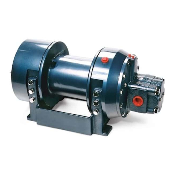
- Page 2 DESCRIPTION OF THE MODEL M5 GENERAL DESCRIPTION: The PULLMASTER Model M5 is a planetary, hydraulic winch having equal speed in both directions. The main components of this unit are: ✛ ✛ ✛ ✛ ✛ hydraulic gear motor ✛ ✛ ✛ ✛ ✛...
- Page 3 EXPLANATION OF MODEL CODING M 5 X - XX - XX - XX X - B XXXX BASIC UNIT SERIES = Equal speed in both directions SIZE OF UNIT REDUCTION RATIO Only used for non standard reduction ratios TYPE OF BRAKE Automatic brake, clockwise drum rotation, internal circulation flow Automatic brake, counterclockwise drum rotation, internal circulation flow...
- Page 4 Drum rotation for counter clockwise hoisting direction is available as an option. CABLE DRUM SIZES: Aside from the standard drum sizes listed in APPENDIX A, the PULLMASTER Model M5 planetary winch can be supplied with optional drums to accommodate large wire rope storage capacity.
- Page 5 SPECIFICATIONS Performance specifications are based on standard hydraulic motor, gear ratio and cable drum with 1/2 inch diameter wire rope. For other cable drums and gear ratios, refer to APPENDIX A. Performance specifications for winches supplied with optional motors are provided in attached supplement. CABLE DRUM DIMENSIONS (STANDARD DRUM): Barrel diameter 7.00 in...
- Page 6 PERFORMANCE GRAPHS PG-M5-A LINE PULL VS. OIL PRESSURE: LINE PULL - kN 13.3 17.8 22.3 26.7 2000 1600 1200 1000 2000 3000 4000 5000 6000 LINE PULL - lb LINE SPEED VS. OIL VOLUME: LINE SPEED - m/min 12.2 18.3 24.4 30.5 LINE SPEED - fpm...
- Page 7 TYPICAL HYDRAULIC CIRCUITS HC-M5-A CIRCULATION RETURN LINE DIRECT TO RESERVOIR CONTROL VALVE (MOTOR SPOOL) 4-WAY SPRING RETURN TO CENTER PRESSURE RELIEF VALVE FILTER HYDRAULIC PUMP RESERVOIR 316 REV.030430 PAGE 7...
- Page 8 RECOMMENDATIONS HYDRAULIC FLUID: HYDRAULIC PRESSURE RELIEF: The hydraulic fluid selected for use with PULLMASTER The hydraulic circuit for the PULLMASTER planetary planetary winches should be a high grade, petroleum winch requires a pressure relief set at the operating based fluid, with rust, oxidation and wear resistance.
- Page 9 RESULT IN PROPERTY DAMAGE, SEVERE INJURY OR DEATH. The initial installation or mounting of a PULLMASTER planetary winch is critically important for proper operation and performance. If the winch is mounted to an uneven surface, the centre line of the unit can be distorted to a point where the winch will not operate in either direction.
- Page 10 15020, prEN818-1/9, prEN 1492-1/2, prEN 1677-1/3 and other relevant product standards. 1) The cable drum of the PULLMASTER planetary winch has two cable anchor slots, one for clockwise and one for counterclockwise hoisting. Standard rotation for hoisting is clockwise when looking at the hydraulic motor of the unit.
- Page 11 TROUBLE SHOOTING GENERAL: In most cases, when the hydraulic winch does not perform satisfactorily, the cause for malfunction is found somewhere in the hydraulic circuit. Before the winch is removed from its mounting and disassembled, all of the hydraulic circuit components should be checked for proper function. IMPORTANT: The hydraulic oil volume relates to the line speed or rpm of the winch.
- Page 12 TROUBLE SHOOTING FAILURE PROBABLE CAUSE Brake will not hold. Brake plates or divider plates have been damaged by contamination in the hydraulic fluid or lack of circulation flow in the brake housing. Brake piston is seized in the brake housing because of contamination in the hydraulic fluid.
- Page 13 SERVICE INSTRUCTIONS GENERAL: Before disassembling the PULLMASTER Model M5 planetary winch, read and understand the following instructions. Replace expendable parts such as O-rings and oil seals when reassembling the winch. Have a winch seal kit (Part No. 23099) on hand before the unit is disassembled.
- Page 14 SERVICE INSTRUCTIONS CONTINUED 7) Pull primary sungear, item 440, with brake hub assembly, item 720, and clutch aligners, items 722 and 724, from brake housing. 8) Disassemble brake hub assembly by removing circlip, item 727, from primary sungear, item 440. Remove primary sungear from brake hub, item 720.
- Page 15 SERVICE INSTRUCTIONS CONTINUED DISASSEMBLY OF PRIMARY DRIVE: If the primary drive requires service or repair, disassemble as follows: 1) Remove pipe plug, item 503, from cable drum, item 500, and pipe plug, item 121, from end cover, item 120, to drain lubricating oil from winch interior. Remove breather relief, item 130. NOTE: Breather relief, item 130, is not user serviceable.
- Page 16 SERVICE INSTRUCTIONS CONTINUED REASSEMBLY Thoroughly clean all parts. Use only new, well-greased O-rings and oil seals. Unless otherwise specified, torque fasteners per BOLT TORQUE CHART as back of manual. REASSEMBLY OF FINAL DRIVE: Reassemble final drive end of winch as follows: 1) Press new, well-greased oil seal, item 105, into final housing, item 100.
- Page 17 SERVICE INSTRUCTIONS CONTINUED REASSEMBLY OF BRAKE HOUSING ASSEMBLY: Reassemble brake housing assembly by reversing the disassembly procedure: 1) Place brake spacer, item 712, in end housing with flat side facing up. 2) Install new, well-greased O-ring, item 695, onto mounting flange of brake housing, item 700. Fasten brake housing to end housing using two flat head capscrews, item 693.
- Page 18 SERVICE INSTRUCTIONS CONTINUED REPLACEMENT OF HYDRAULIC MOTOR ASSEMBLY: Replace the hydraulic motor assembly by reversing the removal procedure. IMPORTANT: Before installing motor, determine brake code of winch. Install motor plug as indicated below. SI-1029 MOTOR PLUG WITH 0-RING NOTE: INSERT MOTOR PLUG, O-RING END FIRST, INTO PORT A OR B AS INDICATED IN CHART BELOW.
- Page 19 5) Reassemble the winch as per instructions. 6) Follow INSTALLATION and OPERATING INSTRUCTIONS when returning winch to its mounting. When ordering parts for the PULLMASTER Model M5 planetary winch, always quote the complete model and serial numbers of the unit.
- Page 20 ASSEMBLY DRAWING G1287 316 REV.080130 PAGE 20...
- Page 21 PARTS REFERENCE ITEM NO. QTY. PART NO. DESCRIPTION 20072 FINAL HOUSING 25007 BALL BEARING 070 X 110 X 20 #6014 25006 CIRCLIP ROTOR CLIP HO-433 25008 OIL SEAL 3.000 X 4.003 X .375 20071 END COVER 25032 PIPE PLUG 1/2 NPT SOC HD 20063 SUNGEAR STOPPER 25069...
- Page 22 PARTS REFERENCE - CONTINUED ITEM NO. QTY. PART NO. DESCRIPTION 20183 SPRAG CLUTCH ALIGNER 25187 SPRAG CLUTCH 25492 CIRCLIP ROTOR CLIP SH-106 25483 THRUST WASHER INA # AS 3047 25537 THRUST BEARING INA # AXK 3047 21597 PISTON SUBASSEMBLY 25258 O-RING -90 DURO -247 4-5/8"...
- Page 23 INSTALLATION DIMENSIONS 1127 PAGE 23 REV. 080130...
- Page 24 APPENDIX A LINE PULL LINE SPEED AT MAXIMUM LUBRICATING AT MAXIMUM WIRE ROPE STORAGE CABLE DRUM SIZES PRESSURE* VOLUME* VOLUME FEET INCHES DRUM REQUIRED (MILLIMETERS) (METERS) CODE U.S. POUNDS FEET/MINUTE GALLONS (METERS/MINUTE) (KILONEWTONS) (LITERS) BARE FULL BARE FULL BARREL FLANGE LENGTH 1/2 inch 7/16 inch 3/8 inch DRUM...
- Page 25 APPENDIX B ITEM NUMBERS PART DESCRIPTION BEARING FINAL SUNGEAR CABLE DRUM BASE FLANGE STANDARD REDUCTION RATIO DRUM PART NUMBERS CODE 20078 20067 20068 20074 20078 20297 20068 20074 21008 21019 21018 20325 316 REV.980601 PAGE 25...
- Page 26 BOLT TORQUE CHART TORQUE BOLT DIAMETER TORQUE lb-ft Inches 5/16 7/16 9/16 1085 1000 1356 1200 1627 1500 2034 NOTE: Unless otherwise specified, torque bolts per above chart. 316 REV.980601 PAGE 26...
- Page 27 THE LOGICAL CHOICE INSTRUCTION AND PARTS MANUAL MODEL M6 PLANETARY HYDRAULIC WINCH READ THIS MANUAL BEFORE INSTALLING, OPERATING OR SERVICING THIS PRODUCT. THIS MANUAL CONTAINS IMPORTANT INFORMATION. MAKE THIS MANUAL AVAILABLE TO ALL PERSONS RESPONSIBLE FOR THE OPERATION, INSTALLATION, SERVICING AND MAINTENANCE OF THIS PRODUCT.
- Page 28 DESCRIPTION OF THE MODEL M6 GENERAL DESCRIPTION: The PULLMASTER Model M6 is a planetary, hydraulic winch having equal speed in both directions and an automatic disc brake. The main components of this unit are: ✛ high torque, low speed hydraulic motor ✛...
- Page 29 EXPLANATION OF MODEL CODING M 6 X - XX - XX - X X - X XXXX BASIC UNIT SERIES M = Equal speed in both directions SIZE OF UNIT OPTIONAL REDUCTION RATIO TYPE OF BRAKE Automatic brake, counterclockwise drum rotation, intravent External brake release, automatic brake, counterclockwise drum rotation, intravent External brake release, automatic brake, clockwise drum rotation,...
- Page 30 RELEASE OPTION MUST BE CONNECTED ACCORDING TO TYPICAL HYDRAULIC CIRCUIT. CABLE DRUM SIZES: Aside from the standard drum sizes listed in APPENDIX A, the PULLMASTER Model M6 planetary winch can be supplied with optional drums to accommodate large wire rope storage capacity. DRUM GROOVING: Cable drums for the PULLMASTER Model M6 planetary winch can be grooved.
- Page 31 SPECIFICATIONS Performance specifications are based on standard hydraulic motor, gear ratio and cable drum (drum code -2) with 1/2 inch diameter wire rope. For other cable drums refer to APPENDIX A. Performance specifications for winches supplied with optional motors are provided in attached supplement. CABLE DRUM DIMENSIONS (STANDARD DRUM): Barrel diameter 7.50 in...
- Page 32 PERFORMANCE GRAPHS PG-M6-B LINE PULL VS. OIL PRESSURE: LINE PULL - kN 13.3 17.8 22.2 26.7 29.4 2000 1600 1200 1000 2000 3000 4000 5000 6000 6612 LINE PULL - lb LINE SPEED VS. OIL VOLUME: LINE SPEED - m/min LINE SPEED - fpm Performance graphs are based on standard hydraulic motor and cable drum with 1/2 inch diameter wire rope.
- Page 33 TYPICAL HYDRAULIC CIRCUITS HC-M6-B PULLING APPLICATIONS: 800 PSI [55 BAR] 3 (US) GPM [12 L/MIN] CONTROL VALVE REQUIRED FOR MODELS (MOTOR SPOOL) SUPPLIED WITH EXTERNAL 4-WAY SPRING RETURN TO CENTER BRAKE RELEASE OPTION PRESSURE RELIEF VALVE FILTER HYDRAULIC PUMP RESERVOIR HOISTING APPLICATIONS: COUNTER- BALANCE...
- Page 34 HYDRAULIC PUMP: Hydraulic filter recommendations for the hydraulic circuit For maximum performance of the PULLMASTER of the PULLMASTER planetary winch, based on a return planetary winch, the hydraulic pump must supply the line filter, are given as follows: maximum flow of hydraulic fluid at the hydraulic pressure stated in SPECIFICATIONS.
- Page 35 RESULT IN PROPERTY DAMAGE, SEVERE INJURY OR DEATH. The initial installation or mounting of a PULLMASTER planetary winch is critically important for proper operation and performance. If the winch is mounted to an uneven surface, the centre line of the unit can be distorted to a point where the winch will not operate in either direction.
- Page 36 15020, prEN818-1/9, prEN 1492-1/2, prEN 1677-1/3 and other relevant product standards. 1) The cable drum of the PULLMASTER planetary winch has two cable anchor slots, one for clockwise and one for counterclockwise pulling. Standard rotation for pulling is counterclockwise when looking at the hydraulic motor of the unit.
- Page 37 TROUBLE SHOOTING GENERAL: In most cases, when the hydraulic winch does not perform satisfactorily, the cause of malfunction is found somewhere in the hydraulic circuit. Before the winch is removed from its mounting and disassembled, all of the hydraulic circuit components should be checked for proper function. IMPORTANT: The hydraulic oil volume relates to the line speed or rpm of the winch.
- Page 38 TROUBLE SHOOTING FAILURE PROBABLE CAUSE Friction plates or divider plates have been damaged by Brake will not hold. contamination in the hydraulic fluid, or lack of circulation flow in the brake housing. Brake piston is seized in the brake housing because of contamination in the hydraulic fluid.
- Page 39 In the following service instructions, reference to parts is made by numbers and shown on the applicable group drawings. DISASSEMBLY The majority of service or repair work is accomplished by disassembling the brake housing of the PULLMASTER Model M6 planetary winch. There are no special tools, adjustments or calibrations necessary to service or repair the winch.
- Page 40 SERVICE INSTRUCTIONS CONTINUED 5) Remove pipe plug, item 755, and verify that circulation hole in piston is clear and unobstructed. Re-install pipe plug, item 755. 6) Thoroughly inspect the brake piston outer diameters and brake housing inner bores for scoring caused by hydraulic fluid contamination.
- Page 41 7) Remove and discard oil seal, item 105. If removal of ball bearing, item 103, is necessary, first remove circlip, item 109. The PULLMASTER Model M6 winch has now been completely disassembled. REASSEMBLY Thoroughly clean and lubricate all parts. Use only new, well-greased O-rings and oil seals. Unless otherwise specified, torque fasteners per BOLT TORQUE CHART at back of manual.
- Page 42 SERVICE INSTRUCTIONS CONTINUED REASSEMBLY OF FINAL DRIVE ASSEMBLY: Reassemble final drive assembly by reversing the disassembly procedure. 1) Return winch to a horizontal position, standing on its mounting feet. 2) Install new, well-greased O-ring, item 293, on end of final sungear, item 340, and slide sungear through opening in cable drum, item 500.
- Page 43 SERVICE INSTRUCTIONS CONTINUED 6) Carefully insert the brake piston into the brake housing and turn the piston to line up the bore for the connecting tube, item 830, with the bore in the motor, item 850. 7) Install the eight brake springs, item 752. 8) Install new, well-greased O-ring, item 707, on motor adaptor pilot, item 800.
- Page 44 5) Clean all parts and inspect for wear and damage as per instructions. Replace worn or damaged parts as required. 6) Follow INSTALLATION and OPERATING INSTRUCTIONS when returning winch to its mounting. When ordering parts for the PULLMASTER Model M6 planetary winch, always quote the complete model and serial number of the unit. MODEL NO.
- Page 45 INSTALLATION DIMENSIONS I1062-A 184 REV.051117 PAGE 19...
- Page 46 PARTS REFERENCE - FINAL DRIVE ITEM NO. QTY. PART NO. DESCRIPTION 20868 FINAL HOUSING 25087 BALL BEARING 070 X 125 X 24 # 6214 25933 OIL SEAL 80 X 100 X 7 25086 CIRCLIP ROTOR CLIP HO-500 21149 END COVER 25032 PIPE PLUG 1/2 NPT SOCKET HEAD 20063...
- Page 47 FINAL DRIVE GROUP G1134 Groups drawings may reference more parts than are actually present in a specific assembly. Parts that are referenced on the drawing but are not on the PARTS REFERENCE list should be ignored. 184 REV.950201 PAGE 21...
- Page 48 * These part numbers and descriptions vary according to brake code. Refer to APPENDIX B. ** Do not substitute. Available from PULLMASTER or Authorized Dealer only. Refer to PAGE 20 for winch seal kit and PAGE 24 for ASSEMBLY DRAWING. PAGE 22...
- Page 49 BRAKE GROUP G1133 PAGE 23 184 REV.950201...
- Page 50 ASSEMBLY DRAWING G1133 & G1134 184 REV.950201 PAGE 24...
- Page 51 APPENDIX A LINE PULL LINE SPEED AT MAXIMUM AT MAXIMUM LUBRICATING CABLE DRUM SIZES WIRE ROPE STORAGE PRESSURE* VOLUME* VOLUME INCHES FEET REQUIRED PART DRUM (MILLIMETERS) (METERS) CODE U.S. POUNDS FEET/MINUTE GALLONS (KILONEWTONS) (METERS/MINUTE) BARE FULL BARE FULL 5/8 in 9/16 in 1/2 in BARREL...
- Page 52 APPENDIX B BRAKE CODE - 12 - 13 - 14 - 15 ITEM PART DESCRIPTION PART NUMBERS BRAKE HOUSING 20869 21432 21432 20869 CHECK VALVE 21530 21530 CAPLUG 25374 25374 1/8 NPT PISTON 21153 21402 21402 21153 PIPE PLUG 25370 25370 1/16 NPT PIPE PLUG...
- Page 53 BOLT TORQUE CHART BOLT DIAMETER TORQUE TORQUE Inches lb-ft 5/16 7/16 9/16 1085 1000 1356 1200 1627 1500 2034 NOTE: Unless otherwise specified, torque bolts per above chart. 184 REV.950201 PAGE 27...
- Page 54 THE LOGICAL CHOICE INSTRUCTION AND PARTS MANUAL MODEL M8 PLANETARY HYDRAULIC WINCH READ THIS MANUAL BEFORE INSTALLING, OPERATING OR SERVICING THIS PRODUCT. THIS MANUAL CONTAINS IMPORTANT INFORMATION. MAKE THIS MANUAL AVAILABLE TO ALL PERSONS RESPONSIBLE FOR THE OPERATION, INSTALLATION, SERVICING AND MAINTENANCE OF THIS PRODUCT.
- Page 55 DESCRIPTION OF THE MODEL M8 GENERAL DESCRIPTION: The PULLMASTER Model M8 is a planetary, hydraulic winch having equal speed in both directions. The main components of this unit are: ✛ hydraulic gear motor ✛ multi-disc brake with static and dynamic function ✛...
- Page 56 EXPLANATION OF MODEL CODING M 8 X - XX - XX - XX X - X XXXX BASIC UNIT SERIES = Equal speed in both directions SIZE OF UNIT REDUCTION RATIO Only used for non standard reduction ratios TYPE OF BRAKE Winch without brake Automatic brake, clockwise drum rotation, internal circulation flow Automatic brake, external brake release, clockwise drum rotation,...
- Page 57 HYDRAULIC MOTORS FOR HIGH PRESSURE HYDRAULIC SYSTEMS: The operating pressure of the PULLMASTER Model M8 planetary winch is limited to 2000 psi (138 bar). For hydraulic systems operating with a higher range of hydraulic pressure, the winch can be supplied with a hydraulic piston motor, which will provide for the same basic performance in terms of line pull and line speed capacity.
- Page 58 SPECIFICATIONS Performance specifications are based on standard hydraulic motor, gear ratio and cable drum with 1/2 inch diameter wire rope. For other cable drums and gear ratios, refer to APPENDIX A. Performance specifications for winches supplied with optional motors are provided in attached supplement. CABLE DRUM DIMENSIONS (STANDARD DRUM): Barrel diameter 7.00 in...
- Page 59 PERFORMANCE GRAPHS PG-M8-B LINE PULL VS. OIL PRESSURE LINE PULL - kN 13.4 17.8 22.3 26.7 31.2 37.8 2000 1600 1200 1000 2000 3000 4000 5000 6000 7000 8500 LINE PULL - lb LINE SPEED VS. OIL VOLUME LINE SPEED - m/min LINE SPEED - fpm Performance graphs are based on standard hydraulic motor, gear ratio and cable drum with 1/2 inch diameter wire rope.
- Page 60 TYPICAL HYDRAULIC CIRCUIT HC-M8-B CIRCULATION RETURN LINE DIRECT TO RESERVOIR 800 PSI [55 BAR] 2(US)GPM [8 L/MIN] CIRCULATION SUPPLY LINE REQUIRED FOR MODELS M8: 3 (US) GPM [11 LPM] SUPPLIED WITH EXTERNAL H8: 4 (US) GPM [15 LPM] BRAKE RELEASE OPTION (EXTERNAL CIRCULATION MODELS ONLY) CONTROL VALVE...
- Page 61 RECOMMENDATIONS HYDRAULIC FLUID: HYDRAULIC PRESSURE RELIEF: The hydraulic fluid selected for use with PULLMASTER The hydraulic circuit for the PULLMASTER planetary planetary winches should be a high grade, petroleum winch requires a pressure relief set at the operating based fluid, with rust, oxidation and wear resistance.
- Page 62 RESULT IN PROPERTY DAMAGE, SEVERE INJURY OR DEATH. The initial installation or mounting of a PULLMASTER planetary winch is critically important for proper operation and performance. If the winch is mounted to an uneven surface, the centre line of the unit can be distorted to a point where the winch will not operate in either direction.
- Page 63 15020, prEN818-1/9, prEN 1492-1/2, prEN 1677-1/3 and other relevant product standards. 1) The cable drum of the PULLMASTER planetary winch has two cable anchor slots, one for clockwise and one for counterclockwise hoisting. Standard rotation for hoisting is clockwise when looking at the hydraulic motor of the unit.
- Page 64 TROUBLE SHOOTING GENERAL: In most cases, when the hydraulic winch does not perform satisfactorily, the cause for malfunction is found somewhere in the hydraulic circuit. Before the winch is removed from its mounting and disassembled, all of the hydraulic circuit components should be checked for proper function. IMPORTANT: The hydraulic oil volume relates to the line speed or rpm of the winch.
- Page 65 TROUBLE SHOOTING CONTINUED FAILURE PROBABLE CAUSE Brake plates or divider plates have been damaged by Brake will not hold. contamination in the hydraulic fluid or lack of circulation flow in the brake housing. Brake piston is seized in the brake housing because of contamination in the hydraulic fluid.
- Page 66 For the majority of required service or repair work, disassembly is required only on the brake housing of the PULLMASTER Model M8 planetary winch. There are no special tools needed for the service or repair work and no adjustments or calibrations are necessary. Proceed with the disassembly as follows:...
- Page 67 800, are standard parts of the COMMERCIAL WM31 hydraulic motor, having a 2 inch gear section. All of these parts can be ordered from PULLMASTER or COMMERCIAL INTERTECH dealers in Canada, the United States and in most overseas areas.
- Page 68 SERVICE INSTRUCTIONS CONTINUED 7) Remove four friction plates, item 715, together with five divider plates, item 714, and inspect for damage or wear. Plates should be flat and smooth. Plates should not show heat discoloration. Paper material on friction plates should be intact and grooved. If any damage is detected, replace friction and divider plates as a set. 8) Remove brake spacer, item 712.
- Page 69 SERVICE INSTRUCTIONS CONTINUED 7) Remove sungear stopper, item 444, from primary planet hub, and replace if less than .19 inch thick. 8) To separate cable drum from final housing, first remove circlip, item 513. Insert two heel bars between the flange of the cable drum and the final drive housing and gently pry cable drum out of ball bearing, item 103.
- Page 70 SERVICE INSTRUCTIONS CONTINUED 5) Press new, well-greased oil seal, item 515, into cable drum. 6) Install primary sungear, item 440, into center of three primary planet gears, item 420. Ensure gear teeth are fully engaged by rotating cable drum. REASSEMBLY OF BRAKE HOUSING ASSEMBLY: Reassemble brake housing assembly by reversing the disassembly procedure: 1) If needle bearing, item 603, was removed from center of connecting shaft, item 600, press back into place.
- Page 71 SERVICE INSTRUCTIONS CONTINUED REASSEMBLY OF HYDRAULIC MOTOR: If the hydraulic motor was disassembled, the following procedure should be followed for reassembly: 1) Clean all parts thoroughly before reassembly and apply grease liberally to all seals. Use only new seals (seal kit Part No.
- Page 72 5) Reassemble the winch as per instructions. 6) Follow INSTALLATION and OPERATING INSTRUCTIONS when returning winch to its mounting. When ordering parts for the PULLMASTER Model M8 planetary winch, always quote the complete model and serial numbers of the unit.
- Page 73 PARTS REFERENCE - FINAL DRIVE ITEM NO. QTY. PART NO. DESCRIPTION 21376 FINAL HOUSING 25087 BALL BEARING #6214 25008 OIL SEAL 25086 CIRCLIP ROTOR CLIP HO-500 21812 END COVER 25032 PIPE PLUG 1/2 - 14 NPT 20063 SUNGEAR STOPPER 25069 O-RING -274 10"...
- Page 74 FINAL DRIVE GROUP G1050-B Group drawings may reference more parts than are actually present in a specific assembly. Parts that are referenced on the drawing but are not on the PARTS REFERENCE list should be ignored. PAGE 21 247 REV.960301...
- Page 75 PARTS REFERENCE - BRAKE GROUP PART NO. DESCRIPTION ITEM NO. QTY. 20095 PLANET HUB 21169 PLANET PIN 25060 CIRCLIP ROTOR CLIP C-62 21176 INTERNAL GEAR STOPPER 25119 CIRCLIP ROTOR CLIP SH-62 20101 PLANET GEAR 25064 THRUST WASHER TORRINGTON # TRA 1018 25269 NEEDLE BEARING TORRINGTON # BH1016 21174...
- Page 76 BRAKE GROUP G1058-B PRIOR TO SERIAL NO. 37801: Item 723 - Was Part No. 25071 (Borg Warner sprag clutch # X13143 - Qty. 2) Item 726 - Omitted Group drawings may reference more parts than are actually present in a specific assembly. Parts that are referenced on the drawing but are not on the PARTS REFERENCE list should be ignored.
- Page 77 PARTS REFERENCE - MOTOR GROUP DESCRIPTION ITEM NO. QTY. PART NO. 21973 MOTOR ADAPTOR 25310 O-RING -012 3/8" ID 1/16" CS 25370 PIPE PLUG 1/16 - 27 NPT 25040 PIPE PLUG 1/8 - 27 NPT 25118 CAPSCREW - HEX HEAD 3/8 - 16 NC X 1.25 GRADE 5 25037 LOCKWASHER 3/8"...
- Page 78 MOTOR GROUP G1086 Group drawings may reference more parts than are actually present in a specific assembly. Parts that are referenced on the drawing but are not on the PARTS REFERENCE list should be ignored. PAGE 25 247 REV.950501...
- Page 79 INSTALLATION DIMENSIONS I1025-1-C 247 REV.950501 PAGE 26...
- Page 80 INSTALLATION DIMENSIONS 1025-2 DRUM CODE 11.5 12.6 12.6 15.0 13.500 19.6 6.88 8.000 12.9 342.90 499 174.6 203.20 13.5 13.6 12.6 15.0 13.500 19.6 6.88 8.000 12.9 342.90 499 174.6 203.20 13.5 12.0 13.6 12.6 19.0 17.500 23.6 6.88 8.000 12.9 444.50 599 174.6 203.20...
- Page 81 ASSEMBLY DRAWING G1050-B G1058-A G1086-A 247 REV.960301 PAGE 28...
- Page 82 APPENDIX A LINE PULL LINE SPEED AT MAXIMUM LUBRICATING AT MAXIMUM WIRE ROPE STORAGE CABLE DRUM SIZES PRESSURE* VOLUME* VOLUME FEET INCHES DRUM REQUIRED (MILLIMETERS) (METERS) CODE U.S. POUNDS FEET/MINUTE GALLONS (METERS/MINUTE) (KILONEWTONS) (LITERS) BARE FULL BARE FULL BARREL FLANGE LENGTH 1/2 inch 7/16 inch 3/8 inch DRUM...
- Page 83 APPENDIX B ITEM NUMBERS PART DESCRIPTION PLANET HUB FINAL PLANET FINAL PLANET FINAL CABLE DRUM BASE STOPPER GEAR SUNGEAR STANDARD REDUCTION RATIO DRUM CODE PART NUMBERS 20143 20113 20142 20174 20074 20143 20113 20142 20298 20074 20143 20113 20352 20324 20325 'A' REDUCTION RATIO DRUM...
- Page 84 APPENDIX C BRAKE CODE - 10 ITEM PART DESCRIPTION PART NUMBERS SHUTTLE 20849 20849 20849 20849 ORIFICE 21483 21483 21483 21483 PLUG 1/8-27 NPT 25040 25040 25040 25040 PIPE PLUG 1/8-27 NPT 25040 25040 25040 25040 PIPE PLUG 1/8-27 NPT PIPE 25622 25622...
- Page 85 BOLT TORQUE CHART TORQUE BOLT DIAMETER TORQUE lb-ft Inches 5/16 7/16 9/16 1085 1000 1356 1200 1627 1500 2034 NOTE: Unless otherwise specified, torque bolts per above chart. 247 REV.950501 PAGE 32...
- Page 86 THE LOGICAL CHOICE INSTRUCTION AND PARTS MANUAL MODEL M12 PLANETARY HYDRAULIC WINCH READ THIS MANUAL BEFORE INSTALLING, OPERATING OR SERVICING THIS PRODUCT. THIS MANUAL CONTAINS IMPORTANT INFORMATION. MAKE THIS MANUAL AVAILABLE TO ALL PERSONS RESPONSIBLE FOR THE OPERATION, INSTALLATION, SERVICING AND MAINTENANCE OF THIS PRODUCT.
- Page 87 DESCRIPTION OF THE MODEL M12 GENERAL DESCRIPTION: The PULLMASTER Model M12 is a planetary, hydraulic winch having equal speed in both directions. The main components of this unit are: ✛ hydraulic gear motor ✛ multi-disc brake with static and dynamic function ✛...
- Page 88 EXPLANATION OF MODEL CODING X - XX - XX - XX X - X XXXX BASIC UNIT SERIES M = Equal speed in both directions SIZE OF UNIT REDUCTION RATIO Only used for non standard reduction ratios TYPE OF BRAKE Automatic brake, clockwise drum rotation, internal circulation flow Automatic brake, external brake release, clockwise drum rotation, internal circulation flow...
- Page 89 CHAIN SPROCKET DRIVE: With a chain sprocket in place of the cable drum, the PULLMASTER Model M12 planetary winch can be used as a hydraulic drive motor with the facility of an automatic disc brake. For requirements of this type, the specifications for the chain sprocket must be supplied to the factory.
- Page 90 SPECIFICATIONS Performance specifications are based on standard hydraulic motor, gear ratio and cable drum with 5/8 inch diameter wire rope. For other cable drums refer to APPENDIX A. For other reductions or motors, refer to supplement inside back cover. Performance specifications for winches supplied with optional motors are provided in attached supplement.
- Page 91 PERFORMANCE GRAPHS PG-M12-B LINE PULL VS. OIL PRESSURE LINE PULL - kN 17.8 26.7 35.6 44.5 53.4 2200 2000 1600 1200 2000 4000 6000 8000 10000 12000 LINE PULL - lb LINE SPEED VS. OIL VOLUME LINE SPEED - m/min LINE SPEED - fpm Performance graphs are based on standard hydraulic motor, gear ratio and cable drum with 5/8 inch diameter wire rope.
- Page 92 TYPICAL HYDRAULIC CIRCUIT HC-M12-E 400 PSI [28 BAR] PRESSURE REQUIRED FOR MODELS SUPPLIED 800 PSI [55 BAR] WITH FREESPOOL 2(US)GPM [8 L/MIN] CIRCULATION RETURN LINE REQUIRED FOR MODELS OPTION (MUST GO DIRECT SUPPLIED WITH EXTERNAL TO RESERVOIR) BRAKE RELEASE OPTION CIRCULATION SUPPLY LINE M12: 3.5 (US) GPM [13 LPM] H12: 4.5 (US) GPM [17 LPM]...
- Page 93 SPECIFICATIONS. Hydraulic filter recommendations for the hydraulic circuit of the PULLMASTER planetary winch, based on a return HYDRAULIC CONTROL VALVE: line filter, are given as follows: The standard control valve used for operation of the...
- Page 94 RESULT IN PROPERTY DAMAGE, SEVERE INJURY OR DEATH. The initial installation or mounting of a PULLMASTER planetary winch is critically important for proper operation and performance. If the winch is mounted to an uneven surface, the centre line of the unit can be distorted to a point where the winch will not operate in either direction.
- Page 95 15020, prEN818-1/9, prEN 1492-1/2, prEN 1677-1/3 and other relevant product standards. 1) The cable drum of the PULLMASTER planetary winch has two cable anchor slots, one for clockwise and one for counterclockwise hoisting. Standard rotation for hoisting is clockwise when looking at the hydraulic motor of the unit.
- Page 96 TROUBLE SHOOTING GENERAL: In most cases, when the hydraulic winch does not perform satisfactorily, the cause of malfunction is found somewhere in the hydraulic circuit. Before the winch is removed from its mounting and disassembled, all of the hydraulic circuit components should be checked for proper function. IMPORTANT: The hydraulic oil volume relates to the line speed or rpm of the winch.
- Page 97 TROUBLE SHOOTING CONTINUED FAILURE PROBABLE CAUSE Brake will not hold. Brake plates or divider plates have been damaged by contamination in the hydraulic fluid, or lack of circulation flow in the brake housing. Brake piston is seized in the brake housing because of contamination in the hydraulic fluid.
- Page 98 For the majority of required service or repair work, disassembly is required only on the brake housing of the PULLMASTER Model M12 planetary winch. There are no special tools needed for the service or repair work and no adjustments or calibrations are necessary. Proceed with the disassembly as follows:...
- Page 99 800, are standard parts of the WM51 hydraulic motor, having a 2 inch gear section. All of these parts can be ordered from PULLMASTER or Authorized Distributors/Dealers in Canada, the United States and in most overseas areas.
- Page 100 SERVICE INSTRUCTIONS CONTINUED 7) Remove six friction plates, item 715, together with seven divider plates, item 714, and inspect for damage or wear. Plates should be flat and smooth. Plates should not show heat discoloration. Paper material on friction plates should be intact and grooved. If any damage is detected, replace friction and divider plates as a set. 8) Remove brake spacer, item 712.
- Page 101 SERVICE INSTRUCTIONS CONTINUED 8) To separate cable drum from final housing, first remove circlip, item 513. Insert two heel bars between the flange of the cable drum and the final drive housing and gently pry cable drum out of ball bearing, item 103. 9) Remove circlip, item 109, and press ball bearing, item 103, out of final housing, item 100.
- Page 102 SERVICE INSTRUCTIONS CONTINUED 6) Install primary sungear, item 440, into center of three primary planet gears, item 420. Ensure gear teeth are fully engaged by rotating cable drum. REASSEMBLY OF BRAKE HOUSING ASSEMBLY Reassemble brake housing assembly by reversing the disassembly procedure: 1) If needle bearing, item 603, was removed from center of connecting shaft, item 600, press back into place.
- Page 103 SERVICE INSTRUCTIONS CONTINUED REASSEMBLY OF HYDRAULIC MOTOR If the hydraulic motor was disassembled, the following procedure should be followed for reassembly: 1) Clean all parts thoroughly before reassembly and apply grease liberally to all seals. Use only new seals (seal kit Part No.
- Page 104 5) Reassemble the winch as per instructions. 6) Follow INSTALLATION and OPERATING INSTRUCTIONS when returning winch to its mounting. When ordering parts for the PULLMASTER Model M12 planetary winch, always quote the complete model and serial number of the unit.
- Page 105 PARTS REFERENCE - FINAL DRIVE DESCRIPTION ITEM NO. QTY. PART NO. 20283 FINAL HOUSING 25095 BALL BEARING # 6020 25142 OIL SEAL 25093 CIRCLIP ROTOR CLIP HO-600 20169 END COVER 25032 PIPE PLUG 1/2 - 14 NPT 19036 SUNGEAR STOPPER 25088 O-RING -279 13"...
- Page 106 FINAL DRIVE GROUP G1031-A Groups drawings may reference more parts than are actually present in a specific assembly. Parts that are referenced on the drawing but are not on the PARTS REFERENCE list should be ignored. 245 REV.950201 PAGE 21...
- Page 107 PARTS REFERENCE - BRAKE GROUP DESCRIPTION ITEM NO. QTY. PART NO. 25095 BALL BEARING #6020 20095 PLANET HUB 21169 PLANET PIN 25060 CIRCLIP ROTOR CLIP C-62 21176 INTERNAL GEAR STOPPER 25119 CIRCLIP ROTOR CLIP SH-62 20101 PLANET GEAR 25064 THRUST WASHER TORRINGTON # TRA 1018 25269 NEEDLE BEARING TORRINGTON # BH1016 21174...
- Page 108 BRAKE GROUP G1034-A Group drawings may reference more parts than are actually present in a specific assembly. Parts that are referenced on the drawing but are not on the PARTS REFERENCE list should be ignored. 245 REV.971001 PAGE 23...
- Page 109 PARTS REFERENCE - MOTOR GROUP DESCRIPTION ITEM NO. QTY. PART NO. 21390 MOTOR ADAPTOR 25310 O-RING - 012 3/8" ID 1/16" CS 25370 PIPE PLUG 1/16 - 27 NPT 25040 PIPE PLUG 1/8 - 27 NPT 25118 CAPSCREW - HEX HEAD 3/8 - 16 NC X 1.25 GRADE 5 25037 LOCKWASHER 3/8"...
- Page 110 MOTOR GROUP G1033 Group drawings may reference more parts than are actually present in a specific assembly. Parts that are referenced on the drawing but are not on the PARTS REFERENCE list should be ignored. 245 REV.950201 PAGE 25...
- Page 111 INSTALLATION DIMENSIONS I1017-1-E 245 REV.051117 PAGE 26...
- Page 112 INSTALLATION DIMENSIONS I1017-2-D & I1017-3-D Dimensions in inches (Dimensions in millimeters) DRUM 14.6 10.0 15.9 15.6 19.1 17.000 23.8 10.6 8.56 11.000 17.5 (194) (371) 254) (173) (404) (396) (486) (431.80) (604) (269) (217) (279.40) (445) 14.6 10.0 15.9 15.6 19.1 17.000 23.8...
- Page 113 ASSEMBLY DRAWING G1031-A & G1033 & G1034 245 REV.950201 PAGE 28...
- Page 114 APPENDIX A LINE PULL LINE SPEED AT MAXIMUM AT MAXIMUM LUBRICATING WIRE ROPE STORAGE CABLE DRUM SIZES VOLUME* PRESSURE* VOLUME FEET INCHES DRUM REQUIRED (MILLIMETERS) (METERS) CODE U.S. POUNDS FEET/MINUTE GALLONS (METERS/MINUTE) (KILONEWTONS) (LITERS) BARE FULL BARE FULL BARREL FLANGE LENGTH 5/8 in 9/16 in 1/2 in...
- Page 115 APPENDIX B ITEM DRUM CODE FINAL SUNGEAR CABLE DRUM BASE 20198 20201 20148 20198 20186 20148 20305 20299 20293 20198 20300 20148 20198 20302 20148 20305 20309 20293 - 11 20305 21122 21132 245 REV.960215 PAGE 30...
- Page 116 APPENDIX C BRAKE CODE - 10 ITEM PART DESCRIPTION PART NUMBERS SHUTTLE 20849 20849 20849 20849 ORIFICE 21483 21483 21483 21483 PLUG 1/8-27 NPT 25040 25040 25040 25040 PIPE PLUG 1/8-27 NPT 25040 25040 25040 25040 PIPE PLUG 1/8-27 NPT PIPE 25622 25622...
- Page 117 BOLT TORQUE CHART BOLT DIAMETER TORQUE TORQUE Inches lb-ft 5/16 7/16 9/16 1085 1000 1356 1200 1627 1500 2034 NOTE: Unless otherwise specified, torque bolts per above chart. 245 REV.950201 PAGE 32...
- Page 118 THE LOGICAL CHOICE INSTRUCTION AND PARTS MANUAL MODEL M18 PLANETARY HYDRAULIC WINCH READ THIS MANUAL BEFORE INSTALLING, OPERATING OR SERVICING THIS PRODUCT. THIS MANUAL CONTAINS IMPORTANT INFORMATION. MAKE THIS MANUAL AVAILABLE TO ALL PERSONS RESPONSIBLE FOR THE OPERATION, INSTALLATION, SERVICING AND MAINTENANCE OF THIS PRODUCT.
- Page 119 DESCRIPTION OF THE MODEL M18 GENERAL DESCRIPTION: The PULLMASTER Model M18 is a planetary, hydraulic winch having equal speed in both directions. The main components of this unit are: ✛ ✛ ✛ ✛ ✛ hydraulic gear motor ✛ ✛ ✛ ✛ ✛...
- Page 120 EXPLANATION OF MODEL CODING X - XX - XX - XX X - X XXXX BASIC UNIT SERIES M = Equal speed in both directions SIZE OF UNIT REDUCTION RATIO Only used for non standard reduction ratios TYPE OF BRAKE Automatic brake, clockwise drum rotation, internal circulation flow Automatic brake, external brake release, clockwise drum rotation, internal circulation flow...
- Page 121 DRUM GROOVING: Cable drums for the PULLMASTER Model M18 planetary winch can be grooved. Where this option is a requirement, it is necessary to state the size of wire rope which is to be used with the winch.
- Page 122 SPECIFICATIONS Performance specifications are based on standard hydraulic motor, gear ratio and cable drum with 3/4 inch diameter wire rope. For other cable drums refer to APPENDIX A. For other reductions or motors, refer to supplement inside back cover. Performance specifications for winches supplied with optional motors are provided in attached supplement.
- Page 123 PERFORMANCE GRAPHS PG-M18-B LINE PULL VS. OIL PRESSURE LINE PULL - kN 13.3 26.7 40.0 53.4 66.7 80.1 2500 2000 1500 1000 3000 6000 9000 12000 15000 18000 LINE PULL - lb LINE SPEED VS. OIL VOLUME LINE SPEED - m/min LINE SPEED - fpm Performance graphs are based on standard hydraulic motor, gear ratio and cable drum with 3/4 inch diameter wire rope.
- Page 124 TYPICAL HYDRAULIC CIRCUIT HC-M18-E 400 PSI (28 BAR) 800 PSI [55 BAR] PRESSURE REQUIRED 2(US)GPM [8 L/MIN] FOR MODELS SUPPLIED REQUIRED FOR MODELS WITH FREESPOOL OPTION SUPPLIED WITH EXTERNAL BRAKE RELEASE OPTION CIRCULATION SUPPLY LINE M18: 5 (US) GPM [19 L/MIN] H18: 7 (US) GPM [26 L/MIN] (EXTERNAL CIRCULATION MODELS ONLY)
- Page 125 HYDRAULIC FILTER: stated in SPECIFICATIONS. Hydraulic filter recommendations for the hydraulic circuit of the PULLMASTER planetary winch, based on a return HYDRAULIC CONTROL VALVE: line filter, are given as follows: The standard control valve used for operation of the...
- Page 126 RESULT IN PROPERTY DAMAGE, SEVERE INJURY OR DEATH. The initial installation or mounting of a PULLMASTER planetary winch is critically important for proper operation and performance. If the winch is mounted to an uneven surface, the centre line of the unit can be distorted to a point where the winch will not operate in either direction.
- Page 127 1) The cable drum of the PULLMASTER planetary winch has two cable anchor slots, one for clockwise and one for counterclockwise hoisting. Standard rotation for hoisting is clockwise when looking at the hydraulic motor of the unit.
- Page 128 TROUBLE SHOOTING GENERAL: In most cases, when the hydraulic winch does not perform satisfactorily, the cause of malfunction is found somewhere in the hydraulic circuit. Before the winch is removed from its mounting and disassembled, all of the hydraulic circuit components should be checked for proper function. IMPORTANT: The hydraulic oil volume relates to the line speed or rpm of the winch.
- Page 129 TROUBLE SHOOTING CONTINUED PROBABLE CAUSE FAILURE Brake plates or divider plates have been damaged by Brake will not hold. contamination in the hydraulic fluid, or lack of circulation flow in the brake housing. Brake piston is seized in the brake housing because of contamination in the hydraulic fluid.
- Page 130 For the majority of required service or repair work, disassembly is required only on the brake housing of the PULLMASTER Model M18 planetary winch. There are no special tools needed for the service or repair work and no adjustments or calibrations are necessary. Proceed with the disassembly as follows:...
- Page 131 SERVICE INSTRUCTIONS CONTINUED REMOVAL OF HYDRAULIC MOTOR ASSEMBLY: If disassembly of the hydraulic motor is not necessary, proceed as follows: 1) Remove the eight hex head capscrews, item 821, with lockwashers, item 823, from the motor adaptor, item 800. Since the brake springs, item 752, apply pressure against the inside of the motor adaptor, it is recommended that the hex capscrews are unscrewed, one turn at a time, until the spring pressure has been released.
- Page 132 SERVICE INSTRUCTIONS CONTINUED 8) Remove brake spacer, item 712. 9) The oil seal, item 607, which seals the brake housing from the cable drum interior, can now be removed and discarded. Remove and discard backup washer, item 606, if used in winch. (Replacement backup washer not required unless included in seal kit.) All parts have now been removed from brake housing and there is no need for further disassembly unless a failure has been analyzed in the remaining winch assembly.
- Page 133 103. 11) Remove the internal circlip, item 109, to remove ball bearing, item 103. Remove and discard oil seal, item 105. The PULLMASTER Model M18 has now been completely disassembled. REASSEMBLY fffffffff Thoroughly clean all parts.
- Page 134 SERVICE INSTRUCTIONS CONTINUED 6) Insert primary sungear, item 440, between three primary planet gears, item 420, and insert sungear shaft into connecting shaft, engaging planet gears with internal gear. Fasten with retaining ring, item 401. 7) Insert final sungear, item 340, into cable drum and engage three planet gears, item 320. 8) Lower brake housing assembly onto cable drum while engaging spline of final sungear with primary planet hub, item 400.
- Page 135 SERVICE INSTRUCTIONS CONTINUED 8) Liberally grease three new O-rings, item 801, and install into the recesses on motor adaptor, item 800. Install new, well-greased O-ring, item 707, on flange of motor adaptor. 9) Slide hydraulic motor assembly onto splined end of motor drive shaft, item 730, and line up pressure transfer holes of brake housing and motor adaptor.
- Page 136 5) Reassemble the winch as per instructions. 6) Follow INSTALLATION and OPERATING INSTRUCTIONS when returning winch to its mounting. When ordering parts for the PULLMASTER Model M18 planetary winch, always quote the complete model and serial number of the unit.
- Page 137 PARTS REFERENCE - FINAL DRIVE ITEM NO. QTY. PART NO. DESCRIPTION FINAL HOUSING 25150 BALL BEARING #6022 26359 OIL SEAL 25153 CIRCLIP ROTOR CLIP HO-662 21968 END COVER 25032 PIPE PLUG 1/2 - 14 NPT 19036 SUNGEAR STOPPER 25488 O-RING -280 14" ID 1/8" CS 21923 RETAINING RING INT 5/32 X 1/4 X 15.5 OD 21180...
- Page 138 FINAL DRIVE GROUP G1043-A Groups drawings may reference more parts than are actually present in a specific assembly. Parts that are referenced on the drawing but are not on the PARTS REFERENCE list should be ignored. 240 REV.980615 PAGE 21...
- Page 139 PARTS REFERENCE - BRAKE GROUP DESCRIPTION ITEM NO. QTY. PART NO. 21944 PLANET HUB 22093 RETAINING RING 21966 PRIMARY PLANET PIN 25961 CIRCLIP ROTOR CLIP C-81 25962 CIRCLIP ROTOR CLIP SH-81 21957 PLANET GEAR 25964 THRUST WASHER TORRINGTON #TRB 1423 25270 LOOSE ROLLER 5/32 X 1.25 TOR.
- Page 140 BRAKE GROUP G1045 Group drawings may reference more parts than are actually present in a specific assembly. Parts that are referenced on the drawing but are not on the PARTS REFERENCE list should be ignored. 240 REV.951201 PAGE 23...
- Page 141 PARTS REFERENCE - MOTOR GROUP DESCRIPTION ITEM NO. QTY. PART NO. 21322 MOTOR DRIVE SHAFT 25288 CIRCLIP ROTOR CLIP C-112 21952 MOTOR ADAPTOR 25127 O-RING -013 7/16"ID 1/16" CS 25040 PIPE PLUG 1/8 - 27 NPT 25031 PIPE PLUG 1/4 -18 NPT 25081 CAPSCREW - HEX HEAD 1/2 - 13NC X 1.50 GRADE 5 25014...
- Page 142 MOTOR GROUP G1017 Group drawings may reference more parts than are actually present in a specific assembly. Parts that are referenced on the drawing but are not on the PARTS REFERENCE list should be ignored. 240 REV.951201 PAGE 25...
- Page 143 INSTALLATION DIMENSIONS I1023-J 240 REV.051117 PAGE 26...
- Page 144 INSTALLATION DIMENSIONS Dimensions in inches (Dimensions in millimeters) DRUM CODE 15.5 10.0 17.9 17.9 15.4 9.430 25.9 10.13 12.9 18.4 13.500 17.8 (216) (394) (254) (210) (454) (454) (392) (239.52) (659) (76) (257.2) (329) (468) (342.90) (451) (147) 13.0 20.0 16.0 20.8 18.5...
- Page 145 ASSEMBLY DRAWING G1017 & G1043-A & G1045 240 REV.001122 PAGE 28...
- Page 146 APPENDIX A LINE PULL LINE SPEED AT MAXIMUM AT MAXIMUM LUBRICATING WIRE ROPE STORAGE CABLE DRUM SIZES PRESSURE* VOLUME* VOLUME FEET INCHES DRUM REQUIRED (MILLIMETERS) (METERS) CODE U.S. FEET/MINUTE POUNDS GALLONS (KILONEWTONS) (METERS/MINUTE) (LITERS) BARE FULL BARE FULL BARREL FLANGE LENGTH 7/8 in 3/4 in 5/8 in...
- Page 147 APPENDIX B DRUM CODE ITEM PART DESCRIPTION PART PART PART PART NUMBER NUMBER NUMBER NUMBER FINAL HOUSING 21916 22047 22047 22047 FINAL SUNGEAR 21964 22050 22050 22212 CABLE DRUM 21953 22036 22398 22194 CAPSCREW 25139 25139 25139 25139 5/8 LOCKWASHER 25359 25359 25359...
- Page 148 APPENDIX C BRAKE CODE - 10 ITEM PART DESCRIPTION PART NUMBERS SHUTTLE 20849 20849 20849 20849 CIRCULATION 20456 20456 20456 20456 VALVE 1/4-18 NPT 25031 25031 25031 25031 PIPE PLUG 1/8-27 NPT 25040 25040 25040 25040 PIPE PLUG 1/8-27 NPT PIPE 25622 25622...
- Page 149 BOLT TORQUE CHART BOLT DIAMETER TORQUE TORQUE Inches lb-ft 5/16 7/16 9/16 1085 1000 1356 1200 1627 1500 2034 NOTE: Unless otherwise specified, torque bolts per above chart. 240 REV.951201 PAGE 32...
- Page 150 THE LOGICAL CHOICE INSTRUCTION AND PARTS MANUAL MODEL M25 PLANETARY HYDRAULIC WINCH READ THIS MANUAL BEFORE INSTALLING, OPERATING OR SERVICING THIS PRODUCT. THIS MANUAL CONTAINS IMPORTANT INFORMATION. MAKE THIS MANUAL AVAILABLE TO ALL PERSONS RESPONSIBLE FOR THE OPERATION, INSTALLATION, SERVICING AND MAINTENANCE OF THIS PRODUCT.
- Page 151 DESCRIPTION OF THE MODEL M25 GENERAL DESCRIPTION: The PULLMASTER Model M25 is a planetary hydraulic winch having equal speed in both directions. The main components of this unit are: ✛ Hydraulic gear motor ✛ Multi disc brake with static and dynamic function ✛...
- Page 152 EXPLANATION OF MODEL CODING X - XX - XX - XX X - X XXXX BASIC UNIT SERIES M = Equal speed in both directions SIZE OF UNIT REDUCTION RATIO Only used for non standard reduction ratios TYPE OF BRAKE Winch without brake Automatic brake, clockwise drum rotation, internal circulation flow Automatic brake, external brake release, clockwise drum rotation,...
- Page 153 HYDRAULIC MOTORS FOR HIGH PRESSURE HYDRAULIC SYSTEMS: The operating pressure of the PULLMASTER Model M25 planetary winch is limited to 2500 psi (172 bar). For hydraulic systems operating with a higher range of hydraulic pressure, the winch can be supplied with a hydraulic piston motor, which will provide for the same basic performance in terms of line pull and line speed capacity.
- Page 154 SPECIFICATIONS Performance specifications are based on standard hydraulic motor, gear ratio and cable drum with 7/8 inch diameter wire rope. For other cable drums refer to APPENDIX A. For other reductions or motors, refer to supplement inside back cover. Performance specifications for winches supplied with optional motors are provided in attached supplement.
- Page 155 PERFORMANCE GRAPHS PG-M25-B LINE PULL VS. OIL PRESSURE LINE PULL - kN 2500 2000 1500 1000 5000 10000 15000 20000 25000 LINE PULL - lb LINE SPEED VS. OIL VOLUME LINE SPEED - m/min LINE SPEED - fpm Performance graphs are based on standard hydraulic motor, gear ratio and cable drum with 7/8 inch diameter wire rope.
- Page 156 TYPICAL HYDRAULIC CIRCUIT HC-M25-C 400 PSI [28 BAR] PRESSURE REQUIRED FOR MODELS SUPPLIED 800 PSI [55 BAR] WITH FREESPOOL OPTION 2(US)GPM [8 L/MIN] REQUIRED FOR MODELS CIRCULATION RETURN LINE SUPPLIED WITH EXTERNAL (MUST GO DIRECT TO RESERVOIR) BRAKE RELEASE OPTION CIRCULATION SUPPLY LINE M25: 5 (US) GPM [19 L/MIN] H25: 7 (US) GPM [26 L/MIN]...
- Page 157 RECOMMENDATIONS HYDRAULIC FLUID: HYDRAULIC PRESSURE RELIEF: The hydraulic fluid selected for use with PULLMASTER The hydraulic circuit for the PULLMASTER planetary planetary winches should be a high grade, petroleum winch requires a pressure relief set at the operating based fluid, with rust, oxidation and wear resistance.
- Page 158 RESULT IN PROPERTY DAMAGE, SEVERE INJURY OR DEATH. The initial installation or mounting of a PULLMASTER planetary winch is critically important for proper operation and performance. If the winch is mounted to an uneven surface, the centre line of the unit can be distorted to a point where the winch will not operate in either direction.
- Page 159 DIN 15020, prEN818-1/9, prEN 1492-1/2, prEN 1677-1/3 and other relevant product standards. 1) The cable drum of the PULLMASTER planetary winch has two cable anchor slots, one for clockwise and one for counterclockwise hoisting. Standard rotation for hoisting is clockwise when looking at the hydraulic motor of the unit.
- Page 160 TROUBLE SHOOTING GENERAL: In most cases, when the hydraulic winch does not perform satisfactorily, the cause of malfunction is found somewhere in the hydraulic circuit. Before the winch is removed from its mounting and disassembled, all of the hydraulic circuit components should be checked for proper function. IMPORTANT: The hydraulic oil volume relates to the line speed or rpm of the winch.
- Page 161 TROUBLE SHOOTING CONTINUED FAILURE PROBABLE CAUSE Brake will not hold. Brake plates or divider plates have been damaged by contamination in the hydraulic fluid, or lack of circulation flow in the brake housing. Brake piston is seized in the brake housing because of contamination in the hydraulic fluid.
- Page 162 For the majority of required service or repair work, disassembly is required only on the brake housing of the PULLMASTER Model M25 planetary winch. There are no special tools needed for the service or repair work and no adjustments or calibrations are necessary. Proceed with the disassembly as follows:...
- Page 163 800, and the port end cover, item 870, are standard parts of the hydraulic motor, having a 3 inch gear section. All of these parts can be ordered from PULLMASTER or authorized Distributors/Dealers in Canada, the United States and in most overseas areas.
- Page 164 SERVICE INSTRUCTIONS CONTINUED 7) Remove five friction plates, item 715, together with six divider plates, item 713, and inspect for damage or wear. Plates should be flat and smooth. Plates should not show heat discoloration. Paper material on friction plates should be intact and grooved.
- Page 165 SERVICE INSTRUCTIONS CONTINUED 14) Remove internal retaining ring, item 534, to remove ball bearing, item 533. Remove and discard oil seal, item 531. 15) Separate cable drum from final housing by first removing circlip, item 513. Insert two heel bars between flange of cable drum and final drive housing and gently pry cable drum out of ball bearing, item 103.
- Page 166 SERVICE INSTRUCTIONS CONTINUED engaging planet gears with internal gear. Fasten with retaining ring, item 401. 9) Insert final sungear, item 340, into cable drum and engage three planet gears, item 320. 10) Lower brake housing assembly onto cable drum, while engaging spline of final sungear with primary planet hub, item 400.
- Page 167 SERVICE INSTRUCTIONS CONTINUED 8) Liberally grease three new O-rings, item 801, and install into recesses on motor adaptor, item 800. Install new, well-greased O-ring, item 707, on flange of motor adaptor. 9) Slide hydraulic motor assembly onto splined end of motor drive shaft, item 730, and line up pressure transfer holes of brake housing and motor adaptor.
- Page 168 5) Reassemble the winch as per instructions. 6) Follow INSTALLATION and OPERATING INSTRUCTIONS when returning winch to its mounting. When ordering parts for the PULLMASTER Model M25 planetary winch, always quote the complete model and serial number of the unit.
- Page 169 PARTS REFERENCE - FINAL DRIVE QTY. DESCRIPTION ITEM NO. PART NO. 20399 FINAL HOUSING 25332 BALL BEARING # 6024 20460 BEARING RETAINER 26359 OIL SEAL 21815 END COVER 25237 PIPE PLUG 3/4 - 14 NPT 19036 SUNGEAR STOPPER 25340 O-RING -281 15" ID 1/8" CS 20416 RETAINING RING 20418...
- Page 170 FINAL DRIVE GROUP G1000-A Group drawings may reference more parts than are actually present in a specific assembly. Parts that are referenced on the drawing but are not on the PARTS REFERENCE list should be ignored. PAGE 21 249 REV.960301...
- Page 171 PARTS REFERENCE - BRAKE GROUP DESCRIPTION ITEM NO. QTY. PART NO. 20404 PLANET HUB 20417 RETAINING RING 20369 PLANET PIN 25004 CIRCLIP ROTOR CLIP C-87 25091 CIRCLIP ROTOR CLIP SH-87 20370 PLANET GEAR 25068 THRUST WASHER TORRINGTON # TRA 1423 25270 LOOSE ROLLER 5/32 X 1.25 TOR.
- Page 172 BRAKE GROUP G1001-B Group drawings may reference more parts than are actually present in a specific assembly. Parts that are referenced on the drawing but are not on the PARTS REFERENCE list should be ignored. PAGE 23 249 REV.970901...
- Page 173 PARTS REFERENCE - MOTOR GROUP ITEM NO. QTY. PART NO. DESCRIPTION 25081 CAPSCREW - HEX HEAD 1/2 - 13 NC X 1.5 GRADE 5 25014 LOCKWASHER 1/2" 20415 MOTOR DRIVE SHAFT 25288 CIRCLIP ROTOR CLIP C-112 20401 MOTOR ADAPTOR 25127 O-RING -013 7/16"...
- Page 174 MOTOR GROUP G1002-D Group drawings may reference more parts than are actually present in a specific assembly. Parts that are referenced on the drawing but are not on the PARTS REFERENCE list should be ignored. PAGE 25 249 REV.970901...
- Page 175 INSTALLATION DIMENSIONS 1001-1-F 249 REV.060714 PAGE 26...
- Page 176 INSTALLATION DIMENSIONS 1001-2-B & 1001-3-B Dimensions in inches (Dimensions in millimeters) DRUM CODE 10.0 17.0 11.0 19.9 19.9 21.0 18.500 28.6 31.0 11.38 20.8 17.750 20.8 (254) (432) (279) (218) (505) (505) (533) (469.90) (726) (787) (289) (225) (527) (450.85) (527) 10.0 24.0...
- Page 177 ASSEMBLY DRAWING G1000 & G1001 & G1002 249 REV.970901 PAGE 28...
- Page 178 APPENDIX A LINE PULL LINE SPEED AT MAXIMUM AT MAXIMUM LUBRICATING WIRE ROPE STORAGE CABLE DRUM SIZES PRESSURE* VOLUME* VOLUME FEET INCHES DRUM REQUIRED (MILLIMETERS) (METERS) CODE U.S. POUNDS FEET/MINUTE GALLONS (METERS/MINUTE) (KILONEWTONS) (LITERS) BARE FULL BARE FULL BARREL FLANGE LENGTH 3/4 inch 7/8 inch 1 inch...
- Page 179 APPENDIX B ITEM 550/552 DRUM CODE SUNGEAR CABLE DRUM BEARING FLANGE BASE 20409 20395 20402 20671 20409 20396 20402 20444 20408 20393 20402 20443 20407 20391 20402 20403 20687 20688 21841 20690 - 10 20687 20935 20402 20937 - 14 20408 20990 20402...
- Page 180 APPENDIX C BRAKE CODE - 10 ITEM PART DESCRIPTION PART NUMBERS SHUTTLE 20849 20849 20849 20849 CIRCULATION 20456 20456 20456 20456 VALVE 1/4-18 NPT 25031 25031 25031 25031 PIPE PLUG 1/8-27 NPT 25040 25040 25040 25040 PIPE PLUG 1/8-27 NPT PIPE 25622 25622...
- Page 181 BOLT TORQUE CHART BOLT DIAMETER TORQUE TORQUE Inches lb-ft 5/16 7/16 9/16 1085 1000 1356 1200 1627 1500 2034 NOTE: Unless otherwise specified, torque bolts per above chart. 249 REV.960301 PAGE 32...
- Page 182 THE LOGICAL CHOICE INSTRUCTION AND PARTS MANUAL MODEL M50 PLANETARY HYDRAULIC WINCH READ THIS MANUAL BEFORE INSTALLING, OPERATING OR SERVICING THIS PRODUCT. THIS MANUAL CONTAINS IMPORTANT INFORMATION. MAKE THIS MANUAL AVAILABLE TO ALL PERSONS RESPONSIBLE FOR THE OPERATION, INSTALLATION, SERVICING AND MAINTENANCE OF THIS PRODUCT.
- Page 183 DESCRIPTION OF THE MODEL M50 GENERAL DESCRIPTION: The PULLMASTER Model M50 is a planetary hydraulic winch having equal speed in both directions. The main components of this unit are: ✛ hydraulic gear motor ✛ multi disc brake with static and dynamic function ✛...
- Page 184 EXPLANATION OF MODEL CODING M 50 X - XX - XX - XX X - X XXXX BASIC UNIT SERIES M = Equal speed in both directions SIZE OF UNIT REDUCTION RATIO Only used for non standard reduction ratios TYPE OF BRAKE Winch without brake Automatic brake, clockwise drum rotation, internal circulation flow Automatic brake, external brake release, clockwise drum rotation,...
- Page 185 HYDRAULIC MOTORS FOR HIGH PRESSURE HYDRAULIC SYSTEMS: The operating pressure of the PULLMASTER Model M50 planetary winch is limited to 2500 psi (172 bar). For hydraulic systems operating with a higher range of hydraulic pressure, the winch can be supplied with a hydraulic piston motor, which will provide for the same basic performance in terms of line pull and line speed capacity.
- Page 186 SPECIFICATIONS Performance specifications are based on standard hydraulic motor, gear ratio and cable drum with 1.25 inch diameter wire rope. For other cable drums refer to APPENDIX A. For other reductions or motors, refer to supplement inside back cover. Performance specifications for winches supplied with optional motors are provided in attached supplement.
- Page 187 PERFORMANCE GRAPHS PG-M50 LINE PULL VS. OIL PRESSURE LINE PULL - kN 2500 2000 1500 1000 5000 10000 15000 20000 25000 30000 35000 40000 45000 50000 LINE PULL - lb LINE SPEED VS. OIL VOLUME LINE SPEED - m/min LINE SPEED - fpm Performance graphs are based on standard hydraulic motor, gear ratio and cable drum with 1.25 inch diameter wire rope.
- Page 188 TYPICAL HYDRAULIC CIRCUIT HC-M50-C 400 PSI (28 BAR) 800 PSI [55 BAR] PRESSURE REQUIRED 2(US)GPM [8 L/MIN] FOR MODELS SUPPLIED REQUIRED FOR MODELS WITH FREESPOOL OPTION SUPPLIED WITH EXTERNAL BRAKE RELEASE OPTION CIRCULATION RETURN LINE (MUST GO DIRECT TO RESERVOIR) CIRCULATION SUPPLY LINE M50: 5(US)GPM - 19 L/MIN H50: 7(US)GPM - 26 L/MIN...
- Page 189 RECOMMENDATIONS HYDRAULIC FLUID: HYDRAULIC PRESSURE RELIEF: The hydraulic fluid selected for use with PULLMASTER The hydraulic circuit for the PULLMASTER planetary planetary winches should be a high grade, petroleum winch requires a pressure relief set at the operating based fluid, with rust, oxidation and wear resistance.
- Page 190 RESULT IN PROPERTY DAMAGE, SEVERE INJURY OR DEATH. The initial installation or mounting of a PULLMASTER planetary winch is critically important for proper operation and performance. If the winch is mounted to an uneven surface, the centre line of the unit can be distorted to a point where the winch will not operate in either direction.
- Page 191 DIN 15020, prEN 818-1/9, prEN 1492-1/2, prEN 1677-1/3 and other relevant product standards. 1) The cable drum of the PULLMASTER planetary winch has two cable anchor slots, one for clockwise and one for counterclockwise hoisting. Standard rotation for hoisting is clockwise when looking at the hydraulic motor of the unit.
- Page 192 TROUBLE SHOOTING GENERAL: In most cases, when the hydraulic winch does not perform satisfactorily, the cause of malfunction is found somewhere in the hydraulic circuit. Before the winch is removed from its mounting and disassembled, all of the hydraulic circuit components should be checked for proper function. IMPORTANT: The hydraulic oil volume relates to the line speed or rpm of the winch.
- Page 193 TROUBLE SHOOTING CONTINUED FAILURE PROBABLE CAUSE Brake plates or divider plates have been damaged by Brake will not hold. contamination in the hydraulic fluid, or lack of circulation flow in the brake housing. Brake piston is seized in the brake housing because of contamination in the hydraulic fluid.
- Page 194 For the majority of required service or repair work, disassembly is required only on the brake housing of the PULLMASTER Model M50 planetary winch. There are no special tools needed for the service or repair work and no adjustments or calibrations are necessary. Proceed with the disassembly as follows:...
- Page 195 800, and the port end cover, item 870, are standard parts of the hydraulic motor, having a 3 inch gear section. All of these parts can be ordered from PULLMASTER or an Authorized Distributor / Dealers in Canada, the United States and in most overseas areas.
- Page 196 SERVICE INSTRUCTIONS CONTINUED 7) Remove five friction plates, item 715, together with six divider plates, item 713, and inspect for damage or wear. Plates should be flat and smooth. Plates should not show heat discoloration. Paper material on friction plates should be intact and grooved.
- Page 197 SERVICE INSTRUCTIONS CONTINUED 9) Connecting shaft, item 600, may now be pulled out of brake housing, and O-ring, item 601, discarded. Inspect needle bearing, item 603, and replace if necessary. 10) To separate secondary housing, item 456, and brake housing, item 700, use a standard bearing puller or insert two heel bars into slot between secondary housing and brake housing and pry brake housing out of spherical roller bearing, item 533.
- Page 198 SERVICE INSTRUCTIONS CONTINUED 13) Insert secondary sungear, item 490, between three planet gears, item 470. Slide assembly into secondary planet housing, item 456, engaging sungear spline with primary planet hub, item 400, and planet gears with secondary planet housing. Insert retaining ring, item 481. 14) Lower brake housing assembly onto cable drum.
- Page 199 SERVICE INSTRUCTIONS CONTINUED 4) Starting and finishing with divider plate, alternately install six divider plates, item 713, and five friction plates, item 715. 5) Liberally grease O-ring, item 751, and O-ring, item 753, and install on brake piston, item 750. 6) Slide brake piston into brake housing with holes for brake springs facing out of brake housing assembly.
- Page 200 SERVICE INSTRUCTIONS CONTINUED 7) Plumb winch assembly to a hydraulic supply and torque motor capscrews according to the following procedure: - Ensure that circulation supply flow is being supplied to the brake housing. - Run the winch, with no load, in the hoisting direction at reduced speed (approximately 30% of maximum hydraulic volume).
- Page 201 5) Reassemble the winch as per instructions. 6) Follow INSTALLATION and OPERATING INSTRUCTIONS when returning winch to its mounting. When ordering parts for the PULLMASTER Model M50 planetary winch, always quote the complete model and serial number of the unit.
- Page 202 ASSEMBLY DRAWING G1002 & G1065 & G1067 253 REV.980701 PAGE 21...
- Page 203 PARTS REFERENCE - FINAL DRIVE QTY. DESCRIPTION ITEM NO. PART NO. FINAL HOUSING 25669 BALL BEARING #6040 21035 RETAINING RING 25670 OIL SEAL 21028 END COVER 25237 PIPE PLUG 3/4 - 14 NPT 20419 SUNGEAR STOPPER 25681 O-RING -391 22" ID 3/16" CS 21029 PLANET HUB STOPPER 25158...
- Page 204 FINAL DRIVE GROUP G1067-C Group drawings may reference more parts than are actually present in a specific assembly. Parts that are referenced on the drawing but are not on the PARTS REFERENCE list should be ignored. 253 REV.110120 PAGE 23...
- Page 205 PARTS REFERENCE - BRAKE GROUP DESCRIPTION ITEM NO. QTY. PART NO. 20172 RETAINING RING 24547 PLANET HUB 20369 PLANET PIN 25004 CIRCLIP ROTOR CLIP C-87 25091 CIRCLIP ROTOR CLIP SH-87 20370 PLANET GEAR 27257 THRUST WASHER TORRINGTON #TRC 1423 25270 LOOSE ROLLER 5/32 X 1.25 TOR.
- Page 206 BRAKE GROUP G1065-B Group drawings may reference more parts than are actually present in a specific assembly. Parts that are referenced on the drawing but are not on the PARTS REFERENCE list should be ignored. 253 REV.980701 PAGE 25...
- Page 207 PARTS REFERENCE - MOTOR GROUP ITEM NO. QTY. PART NO. DESCRIPTION 25081 CAPSCREW - HEX HEAD 1/2-13NC X 1.5 GRADE 5 25014 LOCKWASHER 1/2" 20415 MOTOR DRIVE SHAFT 25288 CIRCLIP ROTOR CLIP C-112 20401 MOTOR ADAPTOR 25127 O-RING -013 7/16" ID 1/16" CS 25040 PIPE PLUG 1/8 - 27 NPT 25031...
- Page 208 MOTOR GROUP G1002-D 253 REV.980701 PAGE 27...
- Page 209 INSTALLATION DIMENSIONS 1029-1-G 253 REV.110124 PAGE 28...
- Page 210 INSTALLATION DIMENSIONS 1029-2-G Dimensions in inches (Dimensions in millimeters) DRUM CODE 14.0 23.8 14.0 26.5 26.8 22.9 17.625 35.3 14.63 27.5 21.000 26.5 (356) (603) (356) (225) (673) (681) (581) (447.68) (897) (371.5) (699) (533.40) (673) (140) 18.0 30.0 22.0 30.5 30.5 30.9 25.625...
- Page 211 APPENDIX A LINE PULL LINE SPEED AT MAXIMUM AT MAXIMUM LUBRICATING WIRE ROPE STORAGE CABLE DRUM SIZES PRESSURE* VOLUME* VOLUME FEET INCHES DRUM REQUIRED (MILLIMETERS) (METERS) CODE U.S. POUNDS FEET/MINUTE GALLONS (METERS/MINUTE) (KILONEWTONS) (LITERS) BARE FULL BARE FULL BARREL FLANGE LENGTH 1 inch 1 inch 1 inch...
- Page 212 APPENDIX B DRUM CODE - 13 ITEM PART DESCRIPTION PART NUMBER (QUANTITY) 21024 21025 21025 FINAL HOUSING ( 1 ) ( 1 ) ( 1 ) 21030 21031 22134 FINAL SUNGEAR ( 1 ) ( 1 ) ( 1 ) 20999 21014 21515...
- Page 213 APPENDIX C BRAKE CODE - 10 ITEM PART DESCRIPTION PART NUMBERS SHUTTLE 20849 20849 20849 20849 CIRCULATION 20456 20456 20456 20456 VALVE 1/4-18 NPT 25031 25031 25031 25031 PIPE PLUG 1/8-27 NPT 25040 25040 25040 25040 PIPE PLUG 1/8-27 NPT 25622 25622 25622...
- Page 214 BOLT TORQUE CHART BOLT DIAMETER TORQUE TORQUE Inches Lb-ft 5/16 7/16 9/16 1085 1000 1356 1200 1627 1500 2034 NOTE: Unless otherwise specified, torque bolts per above chart. 253 REV.980701 PAGE 33...
- Page 215 INSTRUCTION AND PARTS MANUAL MODEL M75 PLANETARY HYDRAULIC WINCH THE LOGICAL CHOICE...
-
Page 216: Table Of Contents
TABLE OF CONTENTS SAFETY RECOMMENDATIONS ..............1 DECRIPTION OF THE MODEL M75 ............2 EXPLANATION OF THE MODEL CODING ..........3 OPTIONS ..................... 4 SPECIFICATIONS ..................5 PERFORMANCE GRAPHS ..............6-7 TYPICAL HYDRAULIC CIRCUIT ............... 8 RECOMMENDATIONS ................9 INSTALATION INSTRUCTIONS ............10-11 OPERATING INSTRUCTIONS .............. -
Page 217: Decription Of The Model M75
DESCRIPTION OF THE MODEL M75 GENERAL DESCRIPTION: The PULLMASTER Model M75 is a planetary hydraulic winch with reversing speeds 4.1 times faster than forward speed. The main components of this unit are: hydraulic gear motor multi disc brake with static and dynamic function... -
Page 218: Explanation Of The Model Coding
EXPLANATION OF MODEL CODING M 75 X - XX - XX - XX X - X XXXX BASIC UNIT SERIES M = Equal Speed SIZE OF UNIT REDUCTION RATIO Only used for non standard reduction ratios TYPE OF BRAKE Automatic brake, clockwise drum rotation, external circulation flow Automatic brake, external brake release, clockwise drum rotation, external circulation flow Automatic brake, external brake release, counterclockwise drum... -
Page 219: Options
HYDRAULIC MOTORS FOR HIGH PRESSURE HYDRAULIC SYSTEMS: The operating pressure of the PULLMASTER Model M75 planetary winch with -191 motor is limited to 3000 psi (270 bar). For hydraulic systems operating with a higher range of hydraulic pressure, the winch can be supplied with a hydraulic piston motor, which will provide for the same basic performance in terms of line pull and line speed capacity. -
Page 220: Specifications
SPECIFICATIONS Performance specifications are based on standard -191 hydraulic motor and gear ratio with 1 1/8" inch diameter wire rope. For other cable drums, reductions or motors, refer to supplement inside back cover. Performance specifications for winches supplied with optional motors are provided in attached supplement. DRUM CODES - 1 Drum - 4 Drum... -
Page 221: Performance Graphs
PERFORMANCE GRAPHS PG-M75 MODEL NUMBER: M75-X-191-1 LINE PULL VS. OIL PRESSURE LINE PULL - kN 3000 2500 2000 1500 1000 7500 15000 22500 30000 37500 45000 52500 60000 67500 75000 LINE PULL - lb LINE SPEED VS. OIL VOLUME LINE SPEED - m/min LINE SPEED - fpm Performance graphs are based on standard hydraulic motor, gear ratio and cable drum with 1 1/8 inch diameter wire rope. - Page 222 PERFORMANCE GRAPHS PG-M75-4 MODEL NUMBER: M75-X-191-4 LINE PULL VS. OIL PRESSURE LINE PULL - kN 3000 2500 2000 1500 1000 7500 15000 22500 30000 37500 45000 52500 60000 67500 75000 80000 85000 LINE PULL - lb LINE SPEED VS. OIL VOLUME LINE SPEED - m/min LINE SPEED - fpm Performance graphs are based on standard hydraulic motor, gear ratio and cable drum with 1 1/8 inch diameter wire...
-
Page 223: Typical Hydraulic Circuit
TYPICAL HYDRAULIC CIRCUIT HC-H/M75-STD EXTERNAL BRAKE RELEASE 800 PSI (55 BAR) AT 1 L/MIN CIRCULATION SUPPLY LINE H75:9(US)GPM (34 L/MIN) M75:7(US)GPM (26 L/MIN) CONTROL VALVE (MOTOR SPOOL) 4-WAY SPRING RETURN TO CENTER PRESSURE RELIEF VALVE FILTER HYDRAULIC PUMP RESERVOIR 354 REV.030819 PAGE 8... -
Page 224: Recommendations
Hydraulic filter recommendations for the hydraulic circuit maximum flow of hydraulic fluid at the hydraulic pressure of the PULLMASTER planetary winch, based on a return stated in SPECIFICATIONS. line filter, are given as follows:... -
Page 225: Instalation Instructions
RESULT IN PROPERTY DAMAGE, SEVERE INJURY OR DEATH. The initial installation or mounting of a PULLMASTER planetary winch is critically important for proper operation and performance. If the winch is mounted to an uneven surface, the centre line of the unit can be distorted to a point where the winch will not operate in either direction. - Page 226 INSTALLATION INSTRUCTIONS CONTINUED 4) Gaps can be adjusted as required by adjusting Jacking Screw diagonally opposite to the Gap. Reduce a gap by turning Jacking Screw clockwise or increase a gap by turning Jack Screw counterclockwise. To adjust Gap “A” TURN Jacking Screw “A”.
-
Page 227: Operating Instructions
DIN 15020, prEN 818-1/9, prEN 1492-1/2, prEN 1677-1/3 and other relevant product standards. 1) The cable drum of the PULLMASTER planetary winch has two pockets for wire rope ferrules, one for clockwise and one for counterclockwise hoisting. Standard rotation for hoisting is clockwise when looking at the hydraulic motor of the unit. -
Page 228: Trouble Shooting
TROUBLE SHOOTING GENERAL: In most cases, when the hydraulic winch does not perform satisfactorily, the cause of malfunction is found somewhere in the hydraulic circuit. Before the winch is removed from its mounting and disassembled, all of the hydraulic circuit components should be checked for proper function. IMPORTANT: The hydraulic oil volume relates to the line speed or rpm of the winch. - Page 229 TROUBLE SHOOTING CONTINUED FAILURE PROBABLE CAUSE Brake plates or divider plates have been damaged by Brake will not hold. contamination in the hydraulic fluid, or lack of circulation flow in the brake housing. Brake piston is seized in the brake housing because of contamination in the hydraulic fluid.
-
Page 230: Service Instructions
For the majority of required service or repair work, disassembly may be required only on the brake housing of the PULLMASTER Model M75 planetary winch. Since the parts are heavy, appropriate care should be taken during disassembly and reassembly. Puller holes are provided on the parts, for safety, use of proper eye-bolts or any other safe means must be used for handling parts during assembly and disassembly of the winch. - Page 231 SERVICE INSTRUCTIONS CONTINUED 1) REMOVAL OF HYDRAULIC MOTOR: (Refer to Parts Reference, APPENDIX B for item numbers) 1.1) Disconnect Brake Hose item 852 from Motor item 850. 1.2) Remove 4 Capscrews item 127 along with Lockwashers item 541 and carefully remove motor from Motor Adaptor item 800.
- Page 232 SERVICE INSTRUCTIONS CONTINUED 3) DISASSEMBLY OF BRAKE HOUSING AND PRIMARY HOUSING: 3.1) Remove 12 Capscrews item 537 and Lockwashers item 541, from Brake Housing item 700, from Primary Housing item 701. Brake Springs item 752, apply pressure against the Primary Housing item701.
- Page 233 SERVICE INSTRUCTIONS CONTINUED 4) DISASSEMBLY OF BRAKE PLATES ONLY: If removal of Brake Piston and Hydraulic Motor is not necessary, proceed as follows: 4.1) Disconnect Brake Hose item 852 4.2) Remove 12 Hex Head Capscrews item 537 and Lock Washers item 541, from Motor Adaptor item 800.
- Page 234 SERVICE INSTRUCTIONS CONTINUED DISASSEMBLY OF PRIMARY PLANETARY DRIVE (item 399): If primary Planet Gears, item 420, must be removed, proceed as follows: 5.1) Remove Circlip item 413 from Planet Pin item 410, and press Planet Pin out of Primary Planet Hub, item 400.
- Page 235 SERVICE INSTRUCTIONS CONTINUED 6) DISASSEMBLY OF SECONDARY PLANETARY DRIVE (item 299). Remove Circlip item 311, from Planet Pin item 310 and press Planet Pin out of Primary Planet Hub item 300. Remove Primary Planet Gear item 320, together with Loose Rollers item 323 and Thrust Washers item 321.
- Page 236 SERVICE INSTRUCTIONS CONTINUED 7) DISASSEMBLY OF BRAKE HUB SUB-ASSEMBLY (item 718) Disassemble Brake Hub Assembly by removing Circlip item 719, from Motor Drive Shaft item 730. Remove Motor Drive Shaft from Brake Hub item 720. Remove Sprag Clutch Aligners item 722 and 724, and Sprag Clutch item 723.
- Page 237 SERVICE INSTRUCTIONS CONTINUED 8) REMOVAL OF DRUM SEAL (item 531): 8.1) Remove Circlip item 344 from Final Sungear item 340, or from Coupling item 341, if present. 8.2) Remove 18 Capscrews item 551, along with Lockwashers item 553, from Secondary Housing item 456, to separate Base item 550, from Secondary Housing.
- Page 238 SERVICE INSTRUCTIONS CONTINUED 11) DISASSEMBLY OF FINAL PLANETARY DRIVE (item 349). If disassembly of Final Planetary Drive is required, proceed as follows: 11.1) Remove Circlip item 361, from Planet Pin item 360. 11.2) Press Planet Pin item 360, out of Planet Hub item 350. 11.3) Remove Planet Gear item 370, out of Planet Hub item 350.
- Page 239 SERVICE INSTRUCTIONS CONTINUED REASSEMBLY Thoroughly clean all parts. Use only new, well greased O-rings and oil seals. Unless otherwise specified, torque fasteners per BOLT TORQUE CHART at back of manual. 1) REASSEMBLY OF FINAL PLANETARY DRIVE (ITEM 349): (Refer to Page 23 for item numbers) Use grease to temporarily hold 30 Loose Rollers item 373, in bore of Planet Gear item 370.
- Page 240 SERVICE INSTRUCTIONS CONTINUED 6) REASSEMBLY OF PRIMARY PLANETARY DRIVE (ITEM 399): (Refer to Page 19 for item numbers) 6.1) If removed install Primary Sungear Stopper item 444, into Planet Hub item 400. 6.2) Use grease to temporarily hold 15 Loose Rollers item 423, in bore of Planet Gear item 420. Position Thrust Washers item 421, on either spline side of Planet Gear.
- Page 241 SERVICE INSTRUCTIONS CONTINUED 8.12) Starting and finishing with a Divider Plate, alternately install 7 Divider Plates item 713, and a 6 Friction Plates item 715. 8.13) Install liberally greased O-ring item 707, in groove Brake Housing item 700. 8.14) Verify Brake Spacer item 712, is installed on Motor Adaptor item 800, and install Motor Adaptor item 800, on Brake Housing item 700.
-
Page 242: Recommended Maintenance
Quote complete model and serial number when ordering parts. MODEL NUMBER __________________________ SERIAL NUMBER __________________________ PULLMASTER WINCH CORPORATION reserves the right to change specifications and the design of PULLMASTER planetary winches at any time without prior notice and without incurring any obligations. PAGE 27 354 REV.030819... -
Page 243: Parts Reference # / Part
PARTS REFERENCE REF NO. QTY. DESCRIPTION PART NO. FINAL HOUSING 26631 BEARING - SPHER. ROLLER SKF # 23948 CC OR EQ. 26634 CIRCLIP ROTOR CLIP DHO-320 25511 OIL SEAL 10.000 X 11.250 X .625 23841 RETAINING RING INT 5/32 X 1/4 X 11.5 OD 23846 END COVER 25237... - Page 244 PARTS REFERENCE DESCRIPTION REF. NO. PART NO. QTY. 21086 BACK-UP WASHER 25345 OIL SEAL DEAMAR 175225312 HP3 23775 BRAKE HOUSING 23838 PRIMARY HOUSING 25557 PLASTIC CAPLUG SAE #20 ORB 25286 O-RING -277 11-1/2"ID 1/8"CS 25339 O-RING -278 12"ID 1/8"CS 23837 BRAKE SPACER 25305 DIVIDER PLATE...
- Page 246 ASSEMBLY DRAWING REFER TO REFER TO PAGE 19 PAGE 20 432 399 REFER TO REFER TO PAGE 23 PAGE 21 REFER TO PAGE 16 537 451 THESE ITEMS ARE SUB-ASSEMBLIES. (FOR PARTS BREAK DOWN REFER TO PAGE NUMBERS SHOWN) THESE ITEMS ARE NOT REQUIRED FOR -1 DRUM CODE PAGE 31 354 REV.
- Page 247 EXPLODED VIEW REFER TO REFER TO PAGE 16 PAGE 20 REFER TO PAGE 21 REFER TO PAGE 19 REFER TO PAGE 23 THESE ITEMS ARE SUB-ASSEMBLIES. (FOR PARTS BREAK DOWN REFER TO PAGE NUMBERS SHOWN) THESE ITEMS ARE NOT REQUIRED FOR -1 DRUM CODE PAGE 32 354 REV.030819...
-
Page 248: Installation Drawing
INSTALLATION DRAWING 1105 PAGE 33 354 REV.051117... -
Page 249: Appendix B (Brake Codes)
APPENDIX A DRUM CODE ITEM PART DESCRIPTION PART NUMBER (QUANTITY) 23752 23923 FINAL HOUSING 23780 23780 FINAL SUNGEAR SUNGEAR 23924 EXTENSION 23833 TAPERED PIN 26642 SET SCREW 23774 23926 CABLE DRUM 23773 23823 BASE PLATE 23772 23822 CAPSCREW (56) (56) LOCKWASHER 25299 25299... - Page 250 APPENDIX B BRAKE CODE ITEM PART DESCRIPTION PART NUMBER (QUANTITY) 26120 26120 90 TUBE ELBOW 26439 26439 26439 26439 TUBE CONNECTOR 26651 26651 SHUTTLE VALVE 26654 26654 UNION 26192 26192 CAPLUG SAE #6 ORB 23995 23995 23836 23836 BRAKE HUB SUB-ASSY PAGE 35 354 REV.030819...
-
Page 251: Bolt Torque Chart
BOLT TORQUE CHART BOLT DIAMETER TORQUE TORQUE Inches Lb-ft 5/16 7/16 9/16 1 1/8 1085 1 1/4 1000 1356 1 3/8 1200 1627 1 1/2 1500 2034 NOTE: Unless otherwise specified, torque bolts per above chart. 354 REV.030819 PAGE 36...
Need help?
Do you have a question about the M5 Series and is the answer not in the manual?
Questions and answers