Table of Contents
Advertisement
Quick Links
Advertisement
Chapters
Table of Contents

Related Manuals for MRC IR-CAM-160

Summary of Contents for MRC IR-CAM-160
- Page 1 Infrared Camera PLEASE READ THIS MANUAL CAREFULLY BEFORE OPERATION 3, Hagavish st. Israel 58817 Tel: 972 3 5595252, Fax: 972 3 5594529 mrc@mrclab.com MRC.06.14...
- Page 2 To Our Customer Dear Customer: Thank you for choosing this Infrared Camera! Please read this user manual carefully before first use. Also please keep in a safe place for reference in the future. Please operate with the recommended instructions in user manual.
- Page 3 WARNING DO NOT USE WHEN RAINING! DO NOT OPEN OR EXCHANGE PARTS! REPAIR ONLY CAN BE CONDUCTED BY STUFF! N O T I C E In order not to cause malfunction or even damage the device please do not direct the lens towards strong high-temperature radiation source (such as the sun) whether the power is on or off! ...
-
Page 4: Table Of Contents
Table of Contents Product Summary ..........1 1.1 Standard Item List ..........2 1.2 Optional Item List ..........2 Battery and Charger..........3 2.1 Charging Battery ..........4 2.2 Direct Charging ............ 4 2.3 Attention for Using Battery Charger...... 4 Panel Function Summary ........ - Page 5 Adjust Temp.......... 26 Save Setting ..........26 5.2.3 Image ............26 Image Setup ..........27 Alarm Switch ......... 28 Alarm Temp .......... 28 Alarm Color ........... 28 Isotherm Color ........28 Isotherm Temp........28 Isotherm Width........28 Screen Display........29 Analysis Setup ..........
-
Page 6: Product Summary
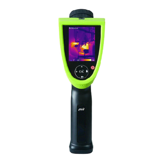
1. Product Summary This new generation Infrared Camera (equipped with Uncooled Focal Plan Array Micro-bolometer) produces crisp thermal image and accurate temperature reading to help increase system maintenance quality and efficiency in many industries. This Infrared Camera is packed with advanced features, such as colored thermal image, voice annotation, sound and color alarm, FLASH memory storage, USB connection to PC, and analysis software. -
Page 7: Standard Item List
1.1 Standard Item List This Series Infrared Camera comes with the following standard items and accessories: Item Quantity Infrared Camera Li-Ion Battery Battery Charger USB Cable Video Cable User Manual IR Analysis Software CD Suitcase 1.2 Optional Item List Wide Angle Lens ... -
Page 8: Battery And Charger
2. Battery and Charger It is recommended to charge battery immediately when device indicates low power. By press and move in the indicated direction, user can easily insert and remove battery. Battery Insertion Battery Removal Device comes with two sets of Li-Ion battery and one battery charger. -
Page 9: Charging Battery
2.1 Charging Battery Following the direction indicated on battery charger, insert the Li-Ion battery, press firmly and push all the way in. During charging, the red LED will be on, and when charging is completed, the green LED will be on instead. ... -
Page 10: Panel Function Summary
3. Panel Function Summary In this manual, “long press” means Long press button down for about 2 seconds, and “press” or “short press” means press and release. 3.1 Main Control Panel 1. Power ON/OFF Button Long press this button to turn on or off the device. 2. - Page 11 Press to freeze Infrared image and press again to unfreeze Long press to save current Infrared image Press ▲ or ▼ to switch between normal view and 2X zoom After press Hotkey button (refer page 8, 3.3) and in area measure mode: ...
-
Page 12: Rear Interface Panel
3.2 Rear Interface Panel 10. Video Output CVBS standard video output. 11. Audio Output Audio output playbacks recorded voice annotation. 12. USB 2.0 Interface USB2.0 interface transfers data between device and PC. 13. External DC In External DC requirement is 12V. -
Page 13: Side View
3.3 Side View 14. Hotkey Button Press Hotkey button to switch between Color Palette, area measurement rectangle, temperature limits, and long press Hotkey button to turn on/off laser sight. 15. Sound Alarm Buzzer Signal sound alarm when reaches temperature limit. 4. -
Page 14: Measure Target Temperature
4.2 Measure Target Temperature 1. Point device to measurement target, and adjust to correct focus. On the upper-right LCD corner, *=×× displays the spot measurement result. For better accuracy, long press OK button to perform manual rectify. 2. Select Area (Rect) Measurement to measure max, min, and average temperature within a rectangle box. -
Page 15: Infrared Image Playback
4.4 Infrared Image Playback Press OK button to open main menu. Select File Manage, and select folder to view stored thermal image. When viewing thermal image, press button or button to switch image in the same folder. icon indicates voice annotation attached to current thermal image. -
Page 16: Connect To Pc
4.6 Connect to PC Connect device to PC using included USB cable. Refer IR Analysis software manual for additional PC operation instruction. It is recommended to format device periodically. 5. Operation Menu 5.1 Display Summary All items can be selected by short pressing the Hotkey button (Note: Long press Hotkey button will turn on/off laser sight). - Page 17 Symbol for 2X zoom: symbol 2X denotes enlarge twice in size; press ▲、▼ button to realize the function. 2, 4 Area measure box: 3 areas can be selected in area measure mode. Horizontal measure line: Horizontal sampling line. Temperature unit: there are three options: 、 、K. Battery condition: indicates current battery power condition.
-
Page 18: Main Menu
5.2 Main Menu Menu and sub-menu items: Press OK button (when not in Hotkey mode) to enter main menu. Note if press OK button too long, instead of enter main menu, triggers manual rectify. Main Menu Using ▲ and ▼ button to select menu item, and selected item is highlighted with white background. -
Page 19: File
5.2.1 File Using File menu to save, playback, delete thermal image and voice annotation. File Sub-menu... -
Page 20: Manage
Manage Select Manage to preview thermal image, add or edit voice annotation, or delete thermal image. File Manage Folder is automatically created if not exist when saving thermal image. Folder name is MYYMMDD, and YYMMDD is year, month, and date. For example, Jan 2 , 2009 folder is M090102. - Page 21 Thermal Image preview Press button to switch saved thermal image in the same folder. The icon indicates voice annotation data with current thermal image. Long press ▲ button to enter Voice Annotation menu. If voice annotation already exists, press Record will record new voice annotation and erase previously saved one.
-
Page 22: Save
Long press ▼ button to delete thermal image. Delete Saved Thermal Image To exit thermal image playback, long press OK button. Save Save current thermal image. Freeze image first before saving. Format Format the internal FLASH memory. Press OK to confirm or cancel to exit. -
Page 23: Spot Measure
Measure Sub-menu Spot Measure Press button to select or deselect. Selected spot is check marked. Up to 4 spots can be selected at the same time. Spot Target Selection... - Page 24 Spot Measure Measure result on upper-right LCD corner is temperature reading at location marked with . Up to 4 spots can be selected. Spot Measure Attribute Press Hotkey button until spot marker is flashing in yellow, and then use ▲, ▼, buttons to move spot location to different directions.
-
Page 25: Line Measure
Emissivity: Refer to Appendix Emissivity of raw materials. Set Reference: Set current spot as reference point. If selected, all measure result will be relative value to this spot temperature. Line Measure There are 2 line measure options: vertical and horizontal. Horizontal Line Measure Horizontal Line Measure Horizontal line is temperature sampling line, and upper-right LCD... - Page 26 Horizontal Line Measure Attribute Vertical Line Measure Vertical Line Measure...
-
Page 27: Area (Rect) Measure
Vertical line is temperature sampling line, and upper-right LCD corner displays temperature measurement reading on horizontal cursor line intersection. After using Hotkey button select line measure, press button to adjust sampling line position, and press ▲ and ▼ button to adjust cursor line position. Press OK button to enter Attribute Menu. - Page 28 Area (Rect) Target Selection Area (Rect) Measure Measure result on upper-right LCD corner is the temperature measurement result within the corresponding rectangle. There are 3 measure types: max, min, and average temperature.
-
Page 29: Parameters
Area (Rect) Measure Attribute Press Hotkey button until area rectangle is flashing in yellow. Press OK button to enter Attribute Menu in which four parameters can be adjusted namely: emissivity, set reference, measure type, move /size. Area (Rect) Measure Attribute Emissivity: Refer to Appendix: Emissivity of raw materials. -
Page 30: Emissivity
Parameter Sub-menu Emissivity Emissivity varies based on target subject material, surface temperature, surface roughness, measurement angle, and etc. Press once to change Emissivity by 0.01. Long press will change Emissivity in 0.1 intervals. Distance This value can be omitted if target subject is close to device (less than 10m). -
Page 31: Adjust Ratio
Adjust Ratio Due to long time usage of device, the sensitivity of IR detector may decrease. In such case, it is necessary to adjust ratio value to get more accurate temperature reading. During calibration, if temperature reading is higher than actual target temperature, change ratio value lower, and vise versa. -
Page 32: Image Setup
Image Sub-menu Image Setup Image Setup Sub-menu... -
Page 33: Alarm Switch
Alarm Switch Press turns on or off the alarm function. If the Alarm Switch is on, when target subject within area box has surface temperature exceeding Alarm Temp, device will alarm with buzzer sound and mark the high temperature location as Alarm Color if Alarm Color is set. -
Page 34: Screen Display
Long press will change Isothermal Width in 1 C interval. Default setting is 1.0 Screen Display When this option is Off, screen display will clear battery condition, temperature unit, temperature limit, and color palette. Press to turn on/ off this option. Analysis Setup Analysis Setup Sub-menu Temp Range... -
Page 35: Temp Unit
Select correct IR Lens for best measurement result. There are 3 options for this infrared camera: 11mm (standard lens), 6.3mm (wide angle lens), and 54mm (telelens). : The camera may need 20 seconds to readjust a new lens before it can work properly. Temp Unit Press to select Temperature Unit from... -
Page 36: Setup
Press OK button to switch between auto and manual rectifying. In manual rectifying mode, upper-left corner of LCD display shows L&S. 5.2.4 Setup There are 4 items in Setup menu: System Setup, Time & Date, Factory Default, and Information. Setup Sub-menu System Setup System Setup includes: Language, Auto Rectify, Auto Save, Video, Transparence, Display Device, Screen Save, and Power... -
Page 37: Language
System Setup Sub-menu Language There are 11 different language options: Simplified Chinese, Traditional Chinese, English, Korean, Japanese, German, French, Russian, Italian, Portuguese and Spanish. Auto Rectify Set the number of seconds to perform next auto-rectify. Set value between 1 and 3000 seconds. Value 0 means disabling auto-rectify feature. -
Page 38: Display Device
Display Device Select between LCD display and external monitor device. Only one video output device can be selected at one time, the other one will be disabled. : If accidentally selected external monitor device and LCD display is disabled, power off and power on device to get LCD display back. -
Page 39: Building Thermal Imaging Summary
6. Building Thermal Imaging Summary As the quality of life improves and the low-carbon life style becomes known, higher demands are being set on buildings. The features of our IR camera make it possible to detect slight temperature difference and to analyze indoor humidity and leakage. - Page 40 The effect drawing of indoor water leakage The effect drawing of indoor corner air leakage...
- Page 41 The effect drawing of outdoor corner air leakage...
-
Page 42: Technical Specification
7. Technical Specification Type New UFPA micro-bolometer Resolution 160×120 Detector Pixel Spacing 25μm Standard Lens 21°×16°/0.15m Wide-angle 35°×27°/0.05m Optional Lens telelens 4°×3°/0.8m Spatial Resolution 2.3mrad( standard lens) Infrared Thermal Sensitivity <60mk at 30℃ Image Frame-frequency 50/60Hz Quality Focusing Manual Digital Zoom Spectral Range 8~14μm Display... - Page 43 Continued table: Technical Specification Storage Media (Built-in Up to over 1500 images Memory) Storage Mode Auto/Manual single frame image storage Storage File Type JPEG, with 14 bits measure data Voice 40 Seconds voice recording Annotation per image (built-in microphone) Laser Director Class 2, 1mW/635nm Red Battery Type...
-
Page 44: Technical Support
8. Technical Support For common mistakes and issues during operation, please refer the following form. If issue cannot be resolved, please contact our technical support department. For simple problems arising during operation, please refer to the following table. If the problem cannot be settled, please cut off the power and contact our technical department. -
Page 45: Appendix: Emissivity Of Raw Material
9. Appendix: Emissivity of Raw Material (For reference purpose only) Material Surface Emissivity (ε) Temp ( inoxidized 0.20 Aluminum Oxidized 0.55 Brown polished 0.40 Brass Unpolished 0.22 Oxidized 0.61 Copper Oxidized badly 0.78 Oxidized 0.74 Iron Rusted 0.65 Oxidized 0.64 Cast Iron inoxidized 0.21... - Page 46 Uncooled Focal Plane Infrared Cameras IRSee Report Software User Manual...
- Page 48 Table of Content Ⅰ. Software Installation..............1 1. Introduction ................1 2. System Requirements............1 2.1 Hardware Configuration ..........1 2.2 Operating System ............1 3. Software Installation..............1 Uninstall Software................3 5. Start Software ...............3 Ⅱ. Function Description ..............4 Image Import and Export ........... 4 1.1 Image Import..............
- Page 49 Disclaimer 1. Limited Liability Software does not guarantee the quality, performance or applicability of any hidden special purpose. The contents of this manual will be updated because of device upgrade or other various reasons. Our company reserves the right to edit this manual without further notice. 2.
-
Page 50: Ⅰ. Software Installation
Ⅰ. Software Installation Welcome to Use IRSee software. 1. Introduction The IRSee Report version has a friendly user interface, 4 methods for measure analysis, and the function to save analysis report in Word, PDF, Excel and other formats. 2. System Requirements The files of the IRSee software consist of IR image, visual image and graphic file, all of which are far bigger than normal text files, thus the following standards of the computer hardware configuration should be... - Page 51 Step A: Running the Setup.exe, the system indicates the installation path, please adjust or change as needed. Step B: Click the Next button to access the software installation. Step C: Click the Next button continuously until the software installation is completed. The system will enter the decoder installation automatically.
-
Page 52: Uninstall Software
4. Uninstall Software Please select the “Delete” button if want to reinstall the software. 5. Starting-up Software The following icon appears on Windows desktop after installing IRSee software. Double-click the icon and startup IRSee interface. Open an image by menu: open or icon in the ribbon. -
Page 53: Ⅱ. Function Description
IRSee software has 10 different working languages, namely: Note: Chinese (simplified & traditional), English, Italian, Japanese, Russian, French, German, Korean, Spanish and Portuguese. IRSee software has auto-recognition language function with the operating system in PC, the IRSee will be in English version if the operating system is beyond mentioned languages in PC. -
Page 54: Image Export
◆ M ethod 2: Click the “Open” button in the ribbon. 1.2 Image Export It is available to export in accordance with the following methods after importing images: ◆ Method 1: Click the button “Save Picture As” button on the software icon on the upper left corner to pop up a file selection dialog box. -
Page 55: Ribbon
2.1 Ribbon The Ribbon is composed of File, Parameters, Audio, Temperature Type Settings, Report Wizard, USB, Panel and Language. 2.1.1 File 2.1.1.1 Open Click the File button to pop up a file selection dialog box. Select and open a file to be analyzed in the dialog box. 2.1.1.2 Save ... - Page 56 2.1.2.2 Humidity Adjustment ● P lease input a required humidity value (1-100) in the humidity edit box. ● P ress the Enter key to confirm. 2.1.2.3 Distance Adjustment ● P lease input a required distance value (1-1000, unit: meter) in the distance edit box.
- Page 57 2.1.5 Report Wizard 2.1.5.1 Report Wizard Report Wizard is used for creating a report, the Report Edit is mainly used for editing a report for further analysis. Click the Report Wizard to select the type of exported report as needed. Click Next to select an image or multiple images.
- Page 58 After necessary information completed, you can click the“save”button to save the report as needed. All reports have the same format of “.HX”, and repots can be edited again in IRSee software.
- Page 60 2.1.5.2 Edit Report If a report is to be closed, the system will prompt whether to save the report or not. Click the OK button. Input and select the saving path and file name, and then click the Save button. Click the report in Ribbon ->>...
- Page 61 Select a saved report to reopen and edit it. 2.1.6 USB Direct-Transmission (only for device with Direct-Transmission function) 2.1.6.1 Connection Click the Ribbon Settings ->> USB Direct-Trans Connect a device, set to USB Direct-Trans mode for the device. Click the device iron on PC software interface ->> Open the device ->> Play 2.1.6.2 Video Click the device ->>...
-
Page 62: Measuring Temperature Zone
2.1.6.4 Pause, Stop and Close Direct-trans Click the Pause, Stop and Close buttons under the File menu respectively to stop the current operation. 2.1.6.5 Print Screen Click the Print Screen button and save the printed image into the Picture folder under the installation directory, and name it by a time format. 2.1.7 Panel It is mainly used for showing/ hiding each area, a user can adjust the size and position of each display area as needed, and then click the “Save... - Page 63 The measurement objects can analyze the thermal images by the following three kinds of analysis methods: point, line, and area. Line measurement analysis has four types: arbitrary line, horizontal line, vertical line and multiple-line analysis. Area measurement analysis has below: rectangular, elliptical and polygonal analysis.
- Page 64 e.g.: If Rectangle 1 and Rectangle 2 are simultaneously selected, Rectangle 1 is smaller than Rectangle 2, Rectangle 1 will prevail. 2.2.2 Point Analysis Create a point Click the button Move the mouse to a point to be analyzed, and click it. Move a point ...
- Page 65 Vertical Line Click the Create button to pop-up a menu. Click the Vertical Line button. Set the vertical coordinates of starting point of the line in the thermal image to be analyzed. Left-hold and drag the mouse to the vertical coordinates of terminal point of the line.
- Page 66 Delete a line Select the line measurement object to be deleted. Click the button to delete selected Measured Objects 2.2.4 Area Analysis It has three areas: rectangle, polygon, and ellipse. Create a rectangle ● C lick the Create Area button to pop up a menu. ●...
- Page 67 Delete a rectangle ● S elect the rectangle object to be deleted. ● C lick the button to delete selected Measured Objects Create a polygon Click the Create Polygon to pop-up a menu. Click the Polygon Select the starting point of the polygon in the thermal image to be analyzed.
- Page 68 Add an ellipse Click the Add Area button to pop-up a menu. ● Click the Ellipse ● Select the starting point of the ellipse in the thermal image to be ● analyzed. Drag the mouse to create an elliptical analysis area. ●...
-
Page 69: Histogram Area
Select image formats Select / set the file path. Click the Save button to save the image . 2.2.6 Clear measured objects Click the Clear Measured Objects button to clear all point, line, area analysis of measured targets. 2.2.7 PIP / Infrared( only for visible image ) Click the button to switch between the PIP and infrared modes. - Page 70 selected, the vertical axis represents the actual number of corresponding measured points. It is available to click the button to switch. 2.3.2 Gradient / Solid Color Display If the gradient histogram display mode is enabled, the system can automatically select corresponding color to fill the histogram in accordance with the temperature;...
-
Page 71: Line Profile Measurement Area
2.3.6 Show / Hide the Out-of-Range Column Click the button to show or hide any column out of temperature range of color code bar, composed of points. 2.3.7 Reset Click the Reset button to reload the default state to the histogram. 2.4 Line Profile Measurement Area 2.4.1 Show /hide grid lines Click the... -
Page 72: Color Code Area
2.4.3 Save the line profile measurement image Click the button to pop up the file selection dialog box. ● Select an image format. ● Check / set the path to save the image. ● Click the Save button to save the line profile measurement image. ●... - Page 73 Drag the mouse to the required temperature value position. Method 2: Click the scroll bar on the arrow button to adjust upper and lower temperature (each step is 0.1) 2.5.3 Adjust upper and lower limits of isothermal color, If the isothermal color is enabled, a user can adjust the isothermal scope ...
-
Page 74: Label Area
2.6 Label Area The Label Area indicates detailed information of measured objects, when the measured object changes, the object's label will change accordingly, the structure of label area is as below: 2.6.1 Set the color of measured object Select a measured object in the label list. ... -
Page 75: Visible Light
2.6.5 Add detailed Information in Image remarks If any object in the label is not selected, it is available to input information. 2.7 Visible Light 2.7.1 Open an Image Click the Open button to pop up the file selection dialog box. ●... - Page 76 2.7.3 Delete an image Click the Delete button to delete the currently added visible image. 2.7.4 Flip an image Click the button to flip an image clockwise or counterclockwise. 2.7.5 PIP This feature is available for any image that with visible light. Click the button to set an image.
- Page 77 Set the transparency ● Drag the lower left progress bar to adjust the PIP values between infrared image and visible image. Set infrared display range ● Drag the right two progress bars to adjust the infrared display range of interval or above upper or below lower limit. Click the “OK”...
Need help?
Do you have a question about the IR-CAM-160 and is the answer not in the manual?
Questions and answers