Table of Contents
Advertisement
Advertisement
Table of Contents

Summary of Contents for Paradox CR-R885-BL
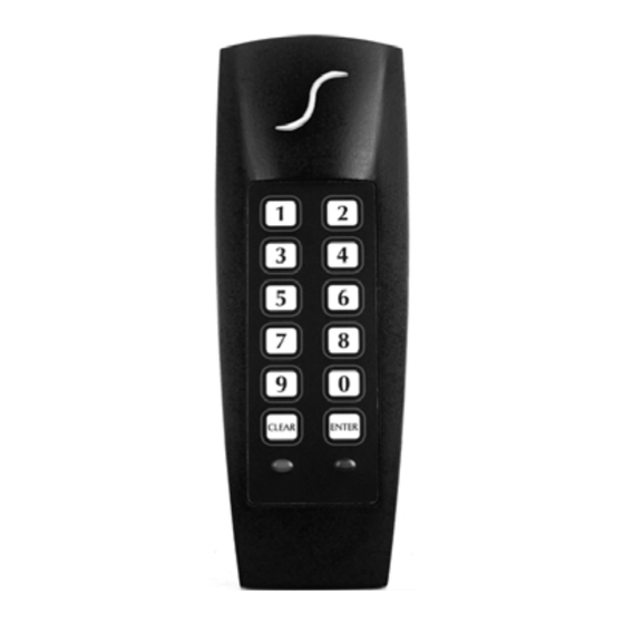
- Page 1 PIN and Proximity Reader For Access Control Systems (CR-R885-BL) Installation and Operating Instructions V1.1 We hope this product performs to your complete satisfaction. Should you have any questions or comments, please visit www.paradox.com and send us your comments.
-
Page 3: Table Of Contents
TABLE OF CONTENTS Selecting an Installation Site: .......2 Mounting and Wiring........2 Mounting on Metal Surfaces ......3 Technical Specifications........3 Feedback ...........5 Programming..........6 Card/Code Options ........7 Keypad Communication Format.....7 Transfer Limit for 4-bits Buffered Format ..8 Display on Card Read........9 Keypad Lockout ..........9 26-bit Wiegand Card Family Code Setting .. -
Page 4: Selecting An Installation Site
INSTALLATION For the reader to function correctly with the access control system, some programming may be required in the controller or control panel of the host system. For further instructions, refer to the appropriate manual. Only explanations directly concerning the reader’s programming will be included in this manual. -
Page 5: Mounting On Metal Surfaces
jacket back 3.175cm (1.25in) and stripping the wires back 0.635cm (0.25in). Splice the reader’s wires with a recommended cable wire. Route the cable to the controller and connect as shown in Figure 1: Connection Drawing on page 5. MOUNTING ON METAL SURFACES Although the read range may slightly decrease, the reader can be mounted on metal. - Page 6 Suggested Cables: 22AWG, 0.8mm, Multi-conductor, Alpha 5196, 5198 18AWG, 1.2mm, Multi-conductor, Alpha 5386, 5388 Belden 9553, 18AWG, 6- conductor, stranded w/overall shield Indicators: Beeper, red LED, green LED, blue or green Face Light Weight: 280g (9.8 oz.) Material: Black, UV resistant, ABS plastic Dimensions: 99.5mm (5.75in.) x 118.5mm (2in.) x 19.5mm (1in.)
-
Page 7: Feedback
Figure 1: Connection Drawing FEEDBACK Visual Feedback: When information is entered on the reader’s keypad, the red and/or green LEDs will flash, remain constant or extinguish depending on the operation. Proximity Reader 5... -
Page 8: Programming
Confirmation Beep: When an operation is successfully entered, the reader emits a rapid series of beep tones (“beep-beep-beep-beep-beep”). Rejection Beep: When the system reverts to a previous status or an operation is incorrectly entered, the reader emits one long beep tone (“beeeeeeeeeep”). -
Page 9: Card/Code Options
5. To program another section, repeat steps 3 and 4. To exit programming mode, press and hold the [ ] key for 4 sec. CLEAR The reader emits a rejection beep and the green LED extinguishes. CARD/CODE OPTIONS Section [001] - Default: [3] The reader can also function as a keypad. -
Page 10: Transfer Limit For 4-Bits Buffered Format
4 bits without parity. 4 bits with parity. 4 bits buffered without parity (also see section [003]). 4 bits buffered with parity (also see section [003]). Note that BCD is not supported. TRANSFER LIMIT FOR 4-BITS BUFFERED FORMAT Section [003] - Default: [00] This feature sets the number of digits retained in memory before the data is sent to the controller. -
Page 11: Display On Card Read
DISPLAY ON CARD READ Section [004] - Default: [3] The response from a card being presented to the reader can be adjusted according to the installation’s requirements. Enter Description Display on Card Read disabled Red Status LED flashes* Green Status LED flashes* Red and green Status LEDs flash* Face Light flashes Face Light and red Status LED flash... -
Page 12: 26-Bit Wiegand Card Family Code Setting
Enter Description Keypad Lockout disabled. Keypad Lockout enabled. 26-BIT WIEGAND CARD FAMILY CODE SETTING Section [006] - Default: [000] When the keypad is enabled, the card’s family code must be programmed in order for the keypad to recognize the user’s PIN. When a user enters a PIN on the keypad, the reader will automatically add the family code programmed in section [006] to the beginning of the PIN before transmitting the data to... -
Page 13: Check-In Supervision
CHECK-IN SUPERVISION Section [008] - Default: [0] This feature only applies when communication format programmed Section [002] is set for Option [1]: 26-bit Wiegand or Option [2]: 37-bit Wiegand. When no actions are performed on the reader for a period of time, it will communicate its status to the controller every 30 seconds by sending a code to confirm its presence (26-bit Wiegand = 255:65535;... -
Page 14: Face Light Intensity
FACE LIGHT INTENSITY Section [102] - Default: [4] The Face Light’s illumination can be adjusted according to the installation’s requirements from 0 (extinguished) to 8 (brightest). Enter Description [0] to [8] Face Light’s intensity level. FACE LIGHT OPERATION Section [103] - Default: [0] The Face Light can be set to remain illuminated continually or can follow the Status LEDs’... -
Page 15: Changing The Installer Code
This feature only applies when Face Light Operation programmed in Section [103] is set for Option [0]: Face Light constant. Enter Description Blue Face Light. Green Face Light. CHANGING THE INSTALLER CODE Section [200] - Default: 000000 The Installer Code is used to enter the reader’s programming mode. -
Page 16: Card Presentation Test
CARD PRESENTATION TEST Present the card to the reader as shown in the figure below. Place the card parallel to the reader and move it toward the reader until the card code displays on the controller screen. At this point, the card is read, decoded, data transmitted to the controller and the controller has responded accordingly. -
Page 17: Warranty
For complete warranty information on this product please refer to the Limited Warranty Statement found on the website www.paradox.com/ terms. Your use of the Paradox product signifies your acceptance of all warranty terms and conditions. © 2003-2007 Paradox Security Systems Ltd. All rights reserved. - Page 18 Notes 16 Installation Manual...
- Page 20 Friday from 8:00 a.m. to 8:00 p.m. EST. For technical support outside Canada and the U.S., call 00-1-450-491-7444, Monday to Friday from 8:00 a.m. to 8:00 p.m. EST. Please feel free to visit our website at www.paradox.com. paradox.com Printed in Canada 11/2007...
Need help?
Do you have a question about the CR-R885-BL and is the answer not in the manual?
Questions and answers