Table of Contents
Advertisement
Quick Links
Advertisement
Table of Contents

Related Manuals for Staheli West DewPoint 6110

Summary of Contents for Staheli West DewPoint 6110
- Page 1 2010-2014 DewPoint 6110 Troubleshooting Guide...
- Page 2 RAISING INDIVIDUAL, FAMILY, AND COMMUNITY STANDARDS WHILE REVOLUTIONIZING THE AGRICULTURAL INDUSTRY. FOR THE MOST UP TO DATE SERVICE INFORMATION VISIT: www.StaheliWest.com/customer FOR SERVICE ASSISTANCE, CONTACT YOUR LOCAL DEALER...
- Page 3 2010-2014 DewPoint 6110 Troubleshooting Guide This manual is intended to be used with software version 2.6 or later installed on the DewPoint 6110 machine See DewPoint 6210 Owners Manual • • Operator Training Operation • • Warranty Information Winterization •...
-
Page 4: Table Of Contents
Contents Informational Fault 201: Turn Burner Switch ON ........... 44 Fault 202: Operating Pressure Control Components Location List ............... VI Switch (OPLS) is tripped ..........44 Diagram 1 Full Machine ..............1 Fault 203: Boiler Water Level is high ..........45 Diagram 2 Boiler Components ............ - Page 5 Contents Fault 402: Faulty PLC Input Card ............59 Test 106: Intermittent Pilot Flame Test ..........78 Fault 403: Boiler water level higher than Test 108: HPLS Calibration [15 PSI] ..........79 set point / Boiler overflowing ......... 60 Test 109: OPLS Calibration [14.5 PSI] ..........80 Fault 404a: Bottom rear work lights will not turn on ......
-
Page 6: Components Location List
Components Location List Component Part # Location Component Part # Location 24v Regulator 10302 Diagram 7 Fuel Solenoid Valves 10730 Diagram 4 Airflow Switch 10041 Diagram 5 Generator Controller 11078 Diagram 1 Ambient Temperature Sensor 10373 Diagram 8 High Pressure Limit Switch 10380 Diagram 3 Blow Down Valve Actuator... -
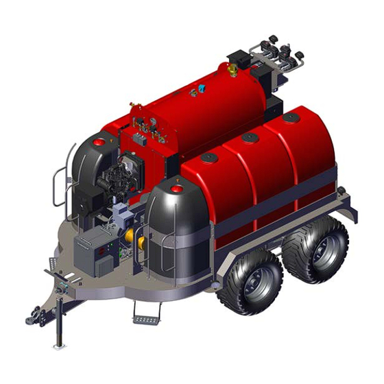
Page 7: Diagram 1 Full Machine
Diagram 1 Boiler Supply Water Generator Tanks Generator Controller Burner Fuel Tanks... -
Page 8: Diagram 2 Boiler Components
Diagram 2 Top Rear Steam Top Front Steam Valve Actuator Valve Actuator Bottom Front Steam Bottom Rear Steam Valve Actuator Valve Actuator Boiler Water Level Sensor Low Water Pressure Relief Cutoff Valve Steam Valve Actuators Flue Steam Purge Valve Actuator Water Purge Valve Actuator Flue Temp. -
Page 9: Diagram 3 Boiler Components
Diagram 3 Operating Pressure High Pressure Pressure Relief Limit Switch (OPLS) Limit Switch (HPLS) Valve Low Water Boiler Water Cutoff Steam PSI 1 Manual Steam Steam PSI 2 Level Sensor Pressure Gauge Boiler Sight Glass Front Turn box Boiler Water Temp. -
Page 10: Diagram 4 Burner Components
Diagram 4 Airflow Switch Flame Detector Burner Nozzle Control Switch High Fire Fuel cylinder/piston Ignition Propane Solenoid Transformer Valve (2014 only) Fan Motor Dual Ignition 2010-2014 Direct Spark Electrodes Burner Gun Assembly Propane Regulator Burner Nozzle (2014 only) 20 GPH 2014 Propane Burner Gun Assembly Propane... -
Page 11: Diagram 5 Burner Components
Diagram 5 Dual Ignition 2010-2014 Direct Spark Electrodes Burner Gun Assembly Fuel Nozzle Burner Nozzle Fuel cylinder pressure gauge Louver 20 GPH push tab Actuator Fuel Return line 2014 Propane Burner Front Boiler Gun Assembly Sight Glass Propane line Low Fire Single Ignition adjustment Propane... -
Page 12: Diagram 6 Panel 1 And Door
Diagram 6a (2010) Panel 1 door Panel 1 Burner Controller (Terminal Strip 1) (Circuit Breakers) Purge Card Burner Controller Modbus Card Flame Amplifier Card Fan Contactor Baldor Soft Start Safety Relays Low Water 2 Low Water 1... -
Page 13: Diagram 7 Panel 2 And 3
Diagram 7a (2010) Panel 2 Panel 3 (Circuit Breakers) (Terminal Strip 1) (Terminal Strip 1) FB (Fuse Block) Control Relay PLC (Programmable Logic Controller) 24v Regulator 12v Regulator RB (Relay Block) FB (Fuse Block) (Terminal Strip 2) Boiler Water Level Sensor... - Page 14 Diagram 6b (2011-2013) Panel 1 door Panel 1 Burner Controller (Terminal Strip 1) (Circuit Breakers) Purge Card Burner Controller Modbus Card Flame Amplifier Card Safety Relays Low Water 2 Low Water 1 Fan Contactor Baldor Soft Start...
- Page 15 Diagram 7b (2011-2013) Panel 2 Panel 3 (Circuit Breakers) (Terminal Strip 1) (Terminal Strip 1) FB (Fuse Block) Control Relay PLC (Programmable Logic Controller) 24v Regulator 12v Regulator RB (Relay Block) FB (Fuse Block) (Terminal Strip 2) Boiler Water Level Sensor...
- Page 16 Diagram 6c (2014-Soft Start) Panel 1 door Panel 1 (Terminal Strip 1) (Circuit Breakers) Burner Controller Safety Relays Burner Controller Fan Contactor Siemens Soft Start Water 1 Water 2 Purge Card Modbus Card Flame Amplifier Card...
- Page 17 Diagram 7c (2014-Soft Start) Panel 2 Panel 3 (Circuit Breakers) (Terminal Strip 1) (Terminal Strip 1) FB (Fuse Block) Control Relay PLC (Programmable Logic Controller) 24v Regulator 12v Regulator RB (Relay Block) FB (Fuse Block) (Terminal Strip 2) Boiler Water Level Sensor...
- Page 18 Diagram 6d (2014-VFD) Panel 1 door Panel 1 Burner Controller (Terminal Strip 1) (Circuit Breakers) Purge Card Burner Controller Modbus Card Flame Amplifier Card Safety Relays Low Water 1 & 2 24v Power...
- Page 19 Diagram 7d (2014-VFD) Panel 2 Panel 3 (Circuit Breakers) (Terminal Strip 1) (Terminal Strip 1) FB (Fuse Block) Control Relay PLC (Programmable Logic Controller) 24v Regulator 12v Regulator RB (Relay Block) FB (Fuse Block) (Terminal Strip 2) Boiler Water Level Sensor...
-
Page 20: Diagram 8 Under Frame
Diagram 8 Burner Fuel Pump Fuel Level Sensor Burner Fuel Filter Low Fire oil Ambient regulating Temp. Sensor valve Supply Water Level Sensor... -
Page 21: Diagram 9 Rear Door Area
Diagram 9 Hot Water Circulation Mixed Water Isolation Valve Cold Water Feed Water Boiler Drain Circulation Feed Water Drain Valve Valve Isolation Valve Actuator Supply Water Isolation Valve Supply Water Feed Water Circulation Supply Water Filter (T-Strainer) Pump Fill Valve Pump *All valves are shown in normal operating positions... -
Page 22: Diagram 10 Engine/Generator
Diagram 10 Water Temperature Switch Glow Plugs Air Filter Radiator Oil Cap Generator End Oil Filter Oil Dipstick Fuel Fuel / Water Oil Pressure Solenoid Separator Switch... -
Page 23: Sensors
Sensors *Same fill color = interchangeable Normal Sensor Function/Range Trip/Alarm Options Pin Out Range 4-20mA Disable in Settings > Alarm Supply Water Level 0-1000 gallons Below 200 gallons Status Screen 4-20mA Disable in Settings > Alarm Fuel Supply Level 0-300 gallons Below 30 gallons Status Screen Disable in Settings >... - Page 24 Sensors *Same fill color = interchangeable Normal Sensor Function/Range Trip/Alarm Options Pin Out Range 4-20mA Selectable and differential More than 2 PSI Steam PSI 1 -14.7 to 30 PSI 6-13 PSI limit adjustable in Settings differential > Boiler Pressure Screen 4-20mA Selectable and differential More than 2 PSI...
- Page 25 Sensors *Same fill color = interchangeable Normal Sensor Function/Range Trip/Alarm Options Pin Out Range Low Fire 80 PSI Fuel Nozzle PSI Gauge 0-400 PSI High Fire 160-190 PSI 4-20mA Black Wire = 24v White Wire = 4-20mA Disable in Settings > Alarm Status Screen Flue Temperature 0-1000°...
-
Page 26: Burner Nozzle Sizes
Burner Nozzle Sizes Choosing the right size burner nozzle can significantly improve a machine’s performance. The higher the elevation, the smaller the nozzle size should be. The number refers to how many gallons per hour the nozzle sprays Less More Steam Output Suggested Case by Case... -
Page 27: Actuators
Actuators Top Front Steam Valve Actuator Top Rear Steam Valve Actuator 1. GND Bottom Front Steam Valve Actuator 2. 4-20mA Actuators are interchangeable Bottom Rear Steam Valve Actuator 3. GND Connections are interchangeable Feed Water Valve Actuator 4. 12v Blow Down Valve Actuator A. -
Page 28: Fuses
Fuses Panel 2 Panel 2 Component Top Front Steam Valve Top Rear Steam Valve Bottom Front Steam Valve Bottom Rear Steam Valve Steam/Water Purge Feed Water Valve BlowDown Valve Panel 3 Panel 3 Component 12v to Actuators, Work Lights 12v to Power Regulator 12v to Generator Start/Stop 12v to 24v Power Regulator 24v to F6... -
Page 29: Circuit Breakers
Circuit Breakers Main Circuit Breaker The Main Circuit Breaker is located on the pas- senger side of the generator behind the generator controller. The breaker needs to be turned ON to be able to operate the machine. 2010 2011-2013 2014 Panel 1 Circuit Breakers Panel 2 Circuit Breakers Feed... -
Page 30: Connections
Connections DT06-2S Work Lights DT06-3S Flue Temp Water/Steam Purge 4-20mA DT06-4S Valve Actuators Tail Light Assembly Work Turn 4-20mA Tail Temp Sensors Fuel/Water Level Sensors PSI Sensors 4-20mA 4-20mA 4-20mA DIN 4 Pin Steam PSI Sensors 4-20mA... - Page 31 Connections Note: 2014 machines only...
- Page 32 Connections...
-
Page 33: Touch Screen Wiring
Touch Screen Wiring 24v to power the Touch Screen 1 2 3 4 24v GND Connection 2A 30-AMP Fuse Panel 3 Panel 2... -
Page 34: Relay Block Wiring
Panel 2 Relay Block Wiring 24v Signal from PLC Red LED “On” when active... -
Page 35: Burner Wiring 2010-2013
Burner Wiring 2010-2013... -
Page 36: Burner Wiring 2014 (Soft Start Direct Spark)
Burner Wiring 2014 (SS Direct Spark) -
Page 37: Burner Wiring 2014 (Soft Start Propane)
Burner Wiring 2014 (SS Propane) -
Page 38: Burner Wiring 2014 (Vfd Propane)
Burner Wiring 2014 (VFD Propane) -
Page 39: Faults
Faults Fault 1: No Purge Card The Honeywell Burner Controller is not detecting a Purge Card (Panel 1) Causes Troubleshooting Fixes • No Purge Card Installed • Check for Purge Card • Install Purge Card • Bad Purge Card • Replace with new Purge Card •... -
Page 40: Fault 15: Flame Detected (Standby)
Faults Fault 15: Flame Detected (Standby) Indicates that a flame has been detected when there should not be a flame Causes Troubleshooting Fixes • Put out the flame • Check for burning/smoldering debris inside • Flame in Boiler • Remove flame source the boiler •... -
Page 41: Fault 17: Main Flame Fail (See Fault 220)
Faults Fault 17: Main Flame Fail Indicates that the flame detector cannot detect flame during run mode (low fire/high fire) Causes Troubleshooting Fixes • Replace Flame Detector (check other causes • Faulty Flame Detector • Perform “Test 101” before buying a new component) •... -
Page 42: Fault 18: Flame Detected (Pre-Purge)
Faults Fault 18: Flame Detected (Pre-Purge) Indicates that a flame has been detected when there should not be a flame Causes Troubleshooting Fixes • Put out the flame • Check for burning/smoldering debris inside • Flame in Boiler • Remove flame source the boiler •... -
Page 43: Fault 19: Main Flame Ign
Faults Fault 19: Main Flame Ign Indicates flame was lost during the first 10 seconds of the RUN state Causes Troubleshooting Fixes • Replace Flame Detector (check other causes • Faulty Flame Detector • Perform “Test 101” before buying a new component) •... -
Page 44: Fault 20: Low Fire Sw Off / Purge Hold
Faults Fault 20: Low Fire SW Off / Purge Hold T18 Low Fire Switch (See Fault 223) Indicates that the Louver is not closing during the purge cycle or that the signal from the Low Fire Switch is not reaching the Honey- well Burner Controller Causes Troubleshooting... -
Page 45: Fault 28: Pilot Flame Fail
Faults Fault 28: Pilot Flame Fail (Page 1 of 2) Indicates a failure in either the ignition system or the safety system that detects the pilot flame IMPORTANT: Perform “Test 101” first to determine whether or not a pilot flame is present Causes Troubleshooting Fixes... - Page 46 Faults Fault 28: Pilot Flame Fail (Page 2 of 2) Indicates a failure in either the ignition system or the safety system that detects the pilot flame IMPORTANT: Perform “Test 101” first to determine whether or not a pilot flame is present Causes Troubleshooting Fixes...
-
Page 47: Fault 29: Lockout Ilk (Airflow Switch / Vfd) (Page 1 Of 2
Faults Fault 29: Lockout ILK (Airflow Switch / VFD) (Page 1 of 2) Indicates that the VFD/fan motor did not turn on or the airflow switch did not detect the fan air moving Causes Troubleshooting Fixes • Clean out aluminum tubes •... -
Page 48: Fault 45: Low Fire Switch Off
Faults Fault 29: Lockout ILK (Airflow Switch / VFD) (Page 2 of 2) Indicates that the VFD/fan motor did not turn on or the airflow switch did not detect the fan air moving • Adjust the load to between: %25 - %50 •... -
Page 49: Fault 200: High Pressure Limit Switch (Hpls) Is Tripped
Faults Fault 200: High Pressure Limit Switch (HPLS) is tripped The High Pressure Limit Switch shuts off the burner anytime it is tripped; it trips anytime boiler pressure is over 15 PSI Causes Troubleshooting Fixes • Have you performed a wet layup recently •... -
Page 50: Fault 201: Turn Burner Switch On
Faults Fault 201: Turn Burner Switch ON Indicates that the burner is not getting 120v power Causes Troubleshooting Fixes • Burner Door Switch is “OFF” • Turn the switch to “ON” • Circuit Breaker B6 is tripped (Panel 1) • Reset the circuit breaker •... -
Page 51: Fault 203: Boiler Water Level Is High
Faults Fault 203: Boiler Water Level is high • See Fault 303: Boiler water level higher than set point / Boiler overflowing Fault 204: Pilot Propane Level is low Indicates that the propane level count is down to 5 remaining lights (this can often be inaccurate) Causes Troubleshooting Fixes... -
Page 52: Fault 207: Pressure Differential Alarm
Faults Fault 207: Pressure Differential Alarm Indicates that the two steam pressure sensors are reading more than 2 PSI (default setting) apart from each other *Bad steam pressure sensors can damage input cards and PLC’s, they can also cause max readings for all inputs on card 1 on the PLC ** If the PLC or input card are replaced before a possible faulty steam pressure sensor is replaced, the steam pressure sensor can damage the newly replaced components. -
Page 53: Fault 208: Flue Temp Is High
Faults Fault 208: Flue Temp is High Indicates flue temperature is above 600° F *Bad Flue temperature sensors can damage input cards and PLC’s, they can also cause max readings for all inputs on card 1 on the PLC ** If the PLC or input card are replaced before a possible faulty flue temp sensor is replaced, the faulty flue temp sensor can damage the newly replaced components. -
Page 54: Fault 209: Feed Water And Boiler Water Temp
Faults Fault 209: Feed Water and Boiler Water Temp. Differential limit has Exceeded Indicates that the difference in temperature between the feed water temperature sensor and the boiler water temperature sensor is more than 150° F Causes Troubleshooting Fixes • Flush Y-Strainer by opening for 3 seconds under steam pressure •... -
Page 55: Fault 210: Ambient Temperature Is High
Faults Fault 210: Ambient Temperature is High Indicates that the ambient temperature is above the alarm set-point (default 100° F) Causes Troubleshooting Fixes • Reconsider using the DewPoint at these temperatures • Compare reading to actual ambient tem- • Ambient temperature is high perature •... -
Page 56: Fault 214: Data Logging Failed: Replace Usb Drive
Faults Fault 214: Data Logging Failed: Replace USB Drive Indicates that the screen can no longer detect the USB flash drive that should be installed at the bottom of the touch screen. This fault will not prevent operation of the machine, but sensor trending will not record. Press “Confirm” to continue operation Causes Troubleshooting Fixes... -
Page 57: Fault 225: Burner Modbus Signal Failure
Faults Fault 225: Burner Modbus signal failure The Mod Bus connection is the way that the Honeywell Burner Controller communicates with the PLC. If the connection is lost, the burner will not function properly. The machine can still operate with Fault 225 active. However, the following features will not display properly: Flame Detector indi- cators, Burner State, Burner Faults, Burner Reset (Burner Reset can only be done in Menu >... -
Page 58: Fault 232: Generator Status
Faults Fault 232: Generator Status (Page 1 of 2) Indicates Generator has failed and shut off for safety Causes Indicates Fixes • Main fuel shutoff valve closed • Open main fuel shutoff valve located beneath the front left fuel tank •... - Page 59 Faults Fault 232: Generator Status (Page 2 of 2) Indicates Generator has failed and shut off for safety Causes Indicates Fixes • Check engine coolant level • High Engine Temperature • Engine Temperature is above normal • Check belt, fan, and radiator •...
-
Page 60: Fault 239: Initiate Hold: Ac Frequency / Noise
Faults Fault 239: Initiate Hold: AC Frequency / Noise Indicates that the Burner Controller has restarted. The Burner has shutoff and will automatically re-fire. This Fault displays if this condition happens twice in 1 hour. If this problem persists, the Burn- er Controller may need to be replaced. -
Page 61: Fault 244: Operating Pressure Control Relay
Faults Fault 244: Operating Pressure Control Relay SR-5 did not annunciate Indicates that the Operating Pressure Control Relay SR-5 did not annunciate. Burner will not operate Causes Troubleshooting Fixes • Faulty SR-5 Relay: Part #781-1C-120A • Swap relay with 120v spare in Panel 1 •... -
Page 62: (Plc-015: Dev001 No Device Found)
Faults Fault 249: Check Network Cable or Fault 214: Missing USB Drive (PLC-015: DEV001 No Device Found) Indicates that the network connection between the PLC and the touch screen has been lost Causes Troubleshooting Fixes • Plug the network cable securely into the •... -
Page 63: Fault 400: Low Water 1 Or 2 Tripped
Faults Fault 400: Low Water 1 or 2 tripped (Page 1 of 2) (Indicates boiler water level is too low for safe operation) Verify that the boiler water sight glass matches the boiler water level on the touch screen Causes Troubleshooting Fixes •... - Page 64 Faults Fault 400: Low Water 1 or 2 tripped (Page 2 of 2) (Indicates boiler water level is too low for safe operation) Verify that the boiler water sight glass matches the boiler water level on the touch screen Causes Troubleshooting Fixes •...
-
Page 65: Fault 401: Boiler Not Filling / Slowly Filling With Water
Faults Fault 401: Boiler not filling / slowly filling with water (See Fault 400) Causes Troubleshooting Fixes • No water in the supply tanks • See Fault 206 • Supply Water Filter (T-Strainer) is plugged • Remove and inspect the screen for debris •... -
Page 66: Fault 403: Boiler Water Level Higher Than
Faults Fault 403: Boiler water level higher than set point / Boiler overflowing Causes Troubleshooting Fixes • Have you performed a wet layup recently • Wet Layup (Wet Layup fills the boiler completely full of • Drain water from boiler to desired level water) •... -
Page 67: Fault 404A: Bottom Rear Work Lights Will Not Turn On
Faults Fault 404.A: Bottom rear work lights will not turn on (All work lights not working 2010-2012 machines) Tractor controls the bottom rear work lights Causes Troubleshooting Fixes • Trailer light harness disconnected • Check light harness • Plug the harness in •... -
Page 68: Fault 405: Touch Screen Controller Will Not Turn On
Faults Fault 405: Touch Screen controller will not turn on Causes Troubleshooting Fixes • Low battery voltage • Start the generator • Charge/replace battery • Blown fuse F4, F5, F10, F12 (Panel 3) • Fuse should light up with a red LED if blown •... -
Page 69: Fault 407: Burner Smoking
Faults Fault 407: Burner Smoking (Page 1 of 2) Indicates burner air : fuel ratio is not working properly. A puff of smoke every 10 seconds is normal for the 6110 (Black smoke = not enough air / too much fuel) (White smoke = too much air / not enough fuel) Causes Troubleshooting Fixes... -
Page 70: Fault 408: Actuators/Valves Not Opening/Closing
Faults Fault 407: Burner Smoking (Page 2 of 2) Indicates burner air : fuel ratio is not working properly. A puff of smoke every 10 seconds is normal for the 6110 (Black smoke = not enough air / too much fuel) (White smoke = too much air / not enough fuel) •... -
Page 71: Fault 409: Loss Of Steam Pressure During Operation
Faults Fault 409: Loss of steam pressure during operation Causes Troubleshooting Fixes • Burner fire shutting off because steam • Test in “Manual Mode” to see if steam • Replace steam purge actuator purge valve is not opening to maintain target purge Actuator moves when turned “ON”... -
Page 72: Fault 410: Feed Water Pump Not Running
Faults Fault 410: Feed Water Pump not running Causes Troubleshooting Fixes • Supply tanks empty • See Fault 206 • Reset pump contactor overload (Panel 2) • Adjust the amperage to 14.5 • Inspect feed pump contactor; if yellow • Pump contactor overload is tripped stripe is present in test window, reset is re- quired •... -
Page 73: Fault 411: Circulation Pump Not Running
Faults Fault 411: Circulation Pump not running Causes Troubleshooting Fixes • Water level must be above Low Water 1 & 2 • Water level is not high enough • Low boiler water level (See Fault 400) for the circulation pump to run •... -
Page 74: Fault 412: Water In Steam / Bales Have Water Splotches
Faults Fault 412: Water in Steam / Bales have Water splotches / Sudden Loss of Steam Pressure and Water Level Indicates poor water quality Causes Troubleshooting Fixes • Supply Water PPM not set correctly on the • Enter correct PPM Setting on boot up screen •... -
Page 75: Fault 413: Pilot Propane Pressure Low
Faults Fault 413: Pilot Propane Pressure Low Causes Troubleshooting Fixes • Propane tank valve closed • Check valve position • Open propane tank valve • Propane tank empty • Check propane level • Refill propane tank • Clogged propane tank regulator •... -
Page 76: Fault 416: Fuel Nozzle Pressure Is Low In High Fire
Faults Fault 416: Fuel Nozzle Pressure is low in High Fire Fuel nozzle pressure is below 160-190 PSI in high fire Causes Troubleshooting Fixes • Low fire fuel regulator is out of adjustment • Low fire fuel pressure should be 80-90 PSI •... -
Page 77: Fault 419: Purge Hold: T19 High Fire Switch
Faults Fault 419: Purge Hold: T19 High Fire Switch (Waiting for Louver to Open) Indicates that the burner louver actuator did not open the louver for purge (Fault 14 indicates the same failure. Fault 14 can take up to 5 minutes to occur) Causes Troubleshooting... -
Page 78: Fault 421: Generator Will Not Start Form Touch Screen
Faults Fault 421: Generator will not start from Touch Screen Causes Troubleshooting Fixes • Temporary fix: Start/Stop the generator manually from the generator controller by • Start/Stop the generator manually from the pressing “Auto” then “Manual Start” • Slightly drained battery generator controller by pressing “Auto”... -
Page 79: Fault 423: Touch Screen Problems: Frozen
Faults Fault 423: Touch Screen Problems: Frozen, won’t respond to touch... Causes Troubleshooting Fixes • Replace USB flash drive • Is the screen locking up / displaying one of • Faulty USB flash drive the messages below? (8gb or smaller) Error message: EA9 An attempt was made to access \Hard Disk\Log\.. -
Page 80: Fault 425: Burner Not Going Into High Fire / Stuck In Low Fire
Faults Fault 425: Burner not going into high fire / Stuck in low fire Causes Troubleshooting Fixes • Burner will not go into high fire until boiler • Let the water warm up to more than 180° F water temperature is above 180° F •... -
Page 81: Fault 426: Failed Pto Bearing(S)
Faults Fault 426: Failed PTO Bearing(s) Indicates poor driveline quality Causes Troubleshooting Fixes • Not greasing bearings every 50 hours • If there is play/movement in the PTO shaft, • Bad PTO shaft angles this indicates that your bearings have failed. •... -
Page 82: Tests
Test 101: Flame Detector Testing Procedures Burner Controller 1. Ensure Control Power is on (Green “POWER” LED) -Generator must be running -Control Power must be enabled on the touch screen 2. Remove Flame Detector 3. Point the flame detector at a light source and confirm the red “FLAME” Purge Card LED lights up on the Burner Controller 4. - Page 83 Test 104: Ignition Transformer Test (2014 machines only) Note: 2013 and older machines; watch for the spark through the sight-glass 1. Disconnect the ignition cable from the transformer 2. Hold the ignition cable eyelet 3/8” - 1/2” away from the ignition transformer post 3.
-
Page 84: Test 106: Intermittent Pilot Flame Test
Test 105.b: Igniter Electrode Orientation & Gap (Page 2 of 2) Propane: 2014 machines) Remove the burner gun assembly (See Test 117) 1. Locate the electrode spark centering hole (end of the burner gun assembly) 2. Position the electrode where the tip is flush with the outside of the propane tube 3. -
Page 85: Test 108: Hpls Calibration [15 Psi]
Test 108: HPLS Calibration [15 PSI] 1. With the boiler full of water, hook up an air hose to the boiler to simulate pressure 2. With the multimeter set to measure ohms, connect your pins to the terminals on SR-3 and SR-4 as shown in #2 3. -
Page 86: Test 109: Opls Calibration [14.5 Psi]
Test 109: OPLS Calibration [14.5 PSI] 1. With the boiler full of water, hook up an air hose to the boiler to simulate pressure 2. With the multimeter set to measure ohms, connect your pins to the terminals on SR-4 and SR-5 as shown in #2 3. - Page 87 Test 110.b: Boiler Water Level Sensor Testing (Page 2 of 2; Old style sensor) 1. Disconnect power to the signal conditioner by removing the two-place green terminal strip fro the conditioner (Panel 3) 2. Check to see if the sensor is working 3.
-
Page 88: Test 111: Valve Repair
Test 111: Valve Repair Before you begin, turn the valve to the fully closed position. Be careful not to damage the surfaces on the valve where the seats will need to seal. 1. Remove the retainer nut from the end of the valve and remove the outer seat and the ball (ball must be in the closed position before it can be re- moved) 2. -
Page 89: Test 112: Pump Service
Test 112: Pump Service NOTICE: The highly polished and lapped faces of this seal are easily damaged. Read instructions and handle the seal with care. Some models are equipped with an impeller screw, which has a left hand thread. Before unscrewing the impeller, remove the impeller screw. REMOVAL OF OLD SEAL INSTALLATION OF FLOATING SEAT (Figure 5C) INSTALLATION OF ROTATING PART OF SEAL UNIT... -
Page 90: Test 113: Input Card Testing
Test 113: Input Card Testing (See Fault 302) • Go to Menu > Diagnostics > Inputs Outputs > Analog Inputs and inspect channels 1-8 on cards 1 & 2 for normal readings. A faulty input card will often max out the readings on one or more channels. •... -
Page 91: Test 114: Program The Vfd (See Fault 29)
Test 114: Program the VFD (See Fault 29) (Only some 2014 machines) • Programming the VFD requires entering the password and adjusting 5 parameters: (P05 = 2, P06 = 3, P19 = 15, P20 = 30, P31 = 60) 1. With the Generator running: Press “Mode” on the VFD 2. -
Page 92: Test 115: Louver Actuator Adjustments
Test 115: Louver Actuator adjusting (See Fault 14) 1. Remove the louver actuator cover by removing the cover screw 2. Press in and lock the “louver locking pin” to free the louver 3. Remove the spanning wrench tool 4. Using the spanning wrench tool adjust the blue home position cam to “zero”. Jam the spanning wrench against the louver actuator housing and use the freed louver linkage arm to adjust the cam (use this method for the red cam also) 5. -
Page 93: Test 116: Tune The Burner
Test 116: Tune the burner (Page 1 of 3) 1. Remove flame detector and burner cover 2. Clean the fan with compressed air and reinstall the burner cover and flame detector 3. Check louver position (Should be about 1/4 inch open; adjust the top bolt as needed) 4. - Page 94 Test 116: Tune the burner (Page 2 of 3) 9. Once the burner advances to Low Fire, follow the four steps below 1- Set the Fuel pump PSI to 280-300 PSI using a flat head screwdriver (Use the physical gauge next to the pump and the digital gauge on the touch screen) a.
- Page 95 Test 116: Tune the burner (Page 3 of 3) 11. Press “High Tune” and wait (Boiler needs to reach 180 degrees Fahrenheit before entering High Fire) 12. Once the boiler reaches 180 degrees Fahrenheit: 1- Adjust the fuel pump pressure to 280-300 PSI 2- Make sure the air louver is 100% open 3- The burner should burn clean when properly tuned (no white/black smoke) 13.
-
Page 96: Test 117: Remove Burner Gun Assembly
Test 117: Remove the burner gun assembly 1. Mark the burner gun assembly depth 2. Loosen sight tube locking bolt; remove the flame detector, cover bolts, nozzle PSI sensor M12 plug, fuel lines and (propane line 2014’s) 3. Lift up then out to remove the cover 4. -
Page 97: Test 118: Update To New Boiler Water Level Sensor
Test 118: Update to new boiler water level sensor (Page 1 of 2) (Update Kit Part # 10344) 1. Remove the old boiler water level sensor 2. Install the new boiler water level sensor using the adapter flange, gasket and bolts 3. - Page 98 Test 118: Update to new boiler water level sensor (Page 2 of 2) (Update Kit Part # 10344) 9. (2010-2013 DewPoint machines) Release the 8th Purple and Red wires and tuck them into the panduit cable hider (they will no longer be used) 10.
-
Page 99: Test 119: Flue Tube Cleaning
Test 119: Flue tube cleaning (Page 1 of 3) Tools needed: Safety goggles, dust mask, shop vac, paint suit, 1.5” flue tube brush (Part # 10178) attached to a 7 foot rod, socket set... 1. Drain the boiler: open the main boiler drain valve 2. - Page 100 Test 119: Flue tube cleaning (Page 2 of 3) 9. Disconnect the flue temp sensor wire harness and remove the flue temp sensor (use the nut, not the head) 10. Remove the rear door cover nuts (and door temp sensor and bracket) 11.
- Page 101 Test 119: Flue tube cleaning (Page 3 of 3) 14. Prepare to brush the flue tubes by attaching the flue tube cleaning brush (Part # 10178) to a 7 foot rod 15. When bushing, be careful not damage the front turn box insulation with the brush as it pushes through the end of the tube 16.
-
Page 102: Test 120: Remove Panel 2 Ts2 Jumpers
If there are 15 white terminal strip, remove the last three green/oragne jumpers Note: This update should be done to all 2010-2013 DewPoint 6110 machines. These extra jumpers are sending 24v power to disconnected sensors and can cause fuses to blow... -
Page 103: Test 121: Generator End Troubleshooting
Test 121: Generator End Troubleshooting (Page 1 of 2) Causes Troubleshooting Fixes • Faulty exciter wires • See Test A • Replace generator • Faulty motor stator • See Test B • Replace generator • Faulty voltage regulator • See Test C •... - Page 104 Test 121: Generator End Troubleshooting (Page 2 of 2) B: Main Stator Test 1. Turn off the main circuit breaker 2. Remove the top 4 screws of the generator cover with a 8mm wrench. 3. Remove the white and green wires from T2 4.
-
Page 105: Test 122: Release Wires From Terminal Block
Test 122: Release wires from terminal block Use a flat head screwdriver to open spring Wire is Wire is locked in inserted... -
Page 106: Test 123: Maxed Out Sensor Readings
Test 123: Maxed out sensor readings Test 123.A: Faulty Sensor / Faulty Wire Harness Test (Multimeter Required) 1. Open Panel 2 (Touch screen should be off) 2. Find the Analog Input terminal strip shown in the picture below 3. Make sure the multimeter is set to measure Ω (Ohms) / Continuity 4. - Page 107 Test 123.B: Faulty Sensor Test (No Multimeter Required) 1. Go to Menu > Diagnostics > Inputs Outputs > Analog Inputs 2. Watch touch screen as you unplug the affected sensors one by one to see if there is a change (A change in the sensor reading may take up to 30 seconds) 3.
-
Page 108: Test 124: All Sensors Offline / Fuse Keeps Blowing
Test 124: All sensors offline / fuse keeps blowing Test 124.A: Faulty Wire Harness Test (Multimeter Required) 1. Open Panel 2 (Touch screen should be off) 2. Find the Analog Input terminal strip shown in the picture below 3. Make sure the multimeter is set to measure Ω (Ohms) / Continuity 4. - Page 109 Test 124.B: Faulty Sensor Test (No Multimeter Required) 1. Unplug all sensors 2. Replace the blown fuse (Panel 3) (if the fuse blows immediately when you turn on the touch screen, go to Test 124.A) 3. Watch touch screen as you plug the sensors in one by one Menu > Diagnostics > Inputs Outputs > Analog Inputs 4.
-
Page 110: Daily
Checklists DAILY EVERY 50 HOURS Grease PTO bearings PRE-OPERATION Check battery and recharge Grease PTO anti-rotating shields Drain water separator Check engine coolant and oil levels Clean radiator fins Check water separator Clean/Replace inner and outer air filters Clean supply water filter (T-strainer) Clean igniter assembly Drain 30-40 gallons of water from boiler Clean flame detector lens... -
Page 111: Every 250 Hours / Yearly
Checklists EVERY 250 HOURS / YEARLY EVERY 500 HOURS Perform 50 hour maintenance Perform 50 hour maintenance Grease fan motor (1 pump) (DO NOT OVER GREASE) Perform 250 hour maintenance Grease and lubricate axles Grease brake cam supports Check/Adjust engine speed so that frequency is 61-62.5hz Grease brake levers Check/Adjust cooling fan v-belt Grease steering rod joints... -
Page 112: Every 1000 Hours
Checklists EVERY 1000 HOURS EVERY 2000 HOURS Perform 50 hour maintenance Perform 50 hour maintenance Perform 250 hour maintenance Perform 250 hour maintenance Perform 500 hour maintenance Perform 500 hour maintenance Flush and replace coolant Perform 1000 hour maintenance Adjust intake / exhaust valve Clearance Replace fuel hoses and coolant hoses EVERY 1500 HOURS Perform 50 hour maintenance... -
Page 113: Maintenance Schedule
MAINTENANCE SCHEDULE See DewPoint 6210 Owners Manual • Operator Training • • • De-Winterization Safety Information Operation • • • • Warranty Information Pre-Operation Requirements Winterization Maintenance Instructions System Check Item Daily 1000 1500 2000 Grease PTO anti-rotating shields Grease and lubricate axles and PTO bearings Grease fan motor (1 pump) (DO NOT OVER GREASE) Grease/Lube Grease brake cam supports... - Page 114 System Check Item Daily 1000 1500 2000 Clean Burner Fan Clean supply water filter (T-strainer) Drain 30-40 gallons of water from boiler Purge hot water through the “Y” strainer for 2-3 seconds Remove crop debris from enclosed areas Purge steam through baler hardware nozzles to clear debris Inspect gauges, sensors, and sight glasses Clean igniter assembly Clean flame detector lens...
- Page 115 System Check Item Daily 1000 1500 2000 Check torque on wheel nuts (325-370 lb-ft) x(1st) Check/Adjust steering hinge gap x(1st) Rotate tires (front to rear) Check/Adjust wheel bearing gap x(1st) Check brake gasket Frame/Axles Check/Adjust brake lever stroke Check torque on shock absorber end screw (295-330 lb-ft) Check torque on steering control cylinder fastening screw (295-330 lb-ft) Check torque on brake cylinder support screw (130-160 lb-ft) Check torque on steering rod end screw (295-330 lb-ft)
- Page 116 Keys to Success Preparation Operation Water Ideal baling moisture, with Always use boiler water treat- Read the “Owner’s Manual” steam, is 11% - 15% ment chemical in boiler water. Always use appropriate water Always make sure hydraulic Never exceed 135° F (57° C) treatment equipment (Softener, brakes are hooked up and internal bale temperature.
Need help?
Do you have a question about the DewPoint 6110 and is the answer not in the manual?
Questions and answers