Advertisement
Quick Links
Advertisement

Subscribe to Our Youtube Channel
Summary of Contents for Clack Valves Water Specialist CI
- Page 1 Water Specialist CI Control Valve Programming and Cover Drawing Manual For Software Revision 317.3...
- Page 2 Page 2 WS1.5CI & 2LCI Man u al...
- Page 3 WS1.5CI & 2LCI Man u al Page 3 CI Front Cover and Drive Assembly Drawing No. Order No. Description Quantity V3175CC-01 WS1CC FRONT COVER ASSEMBLY V3107-01 WS1 MOTOR V3106-01 WS1 DRIVE BRACKET & SPRING CLIP V3108CI-02BOARD WS1 THRU2L CI PCBRD ALT REPLACE V3110 WS1 DRIVE REDUCING GEAR 12X36 V3109...
- Page 4 Page 4 WS1.5CI & 2LCI Man u al Refer to Water Specialist 1.5” and 2L Control Valve Service Manual for the following Drawings and Part Numbers: • *WS1.5 Drive Cap Assembly, Downfl ow Piston, Regenerant Piston, Spacer Stack Assembly, Main Body and Meter •...
- Page 5 WS1.5CI & 2LCI Man u al Page 5 OEM General Instructions The control valve offers multiple procedures that allow the valve to be modifi ed to suit the needs of the installation. These procedures are: • OEM Cycle Sequence • OEM Softener System Setup •...
- Page 6 Page 6 WS1.5CI & 2LCI Man u al Step 1CS – Press NEXT and ▼ simultaneously for 3 seconds and release. Then press NEXT and ▼ STEP 1CS simultaneously for 3 seconds and release. If screen in Step 2CS does not appear in 5 seconds the lock on the valve is activated.
- Page 7 WS1.5CI & 2LCI Man u al Page 7 STEP 5CS Step 5CS – Determine the measurement to calculate volumetric capacity. The choices are: parts per million French degrees German degrees -nA- Using -nA- will allow the OEM to directly place the volume of water treated in place of system capacity in the OEM Softener System Setup level.
- Page 8 Page 8 WS1.5CI & 2LCI Man u al OEM Softener System Setup In OEM Softener System Setup the OEM chooses the time for the cycles selected in OEM Cycle Sequence and specifi es other operating parameters for the system. The upper and lower limits of the allowable values for the cycles are as follows: Cycle Options Units Lower/Upper Limit...
- Page 9 WS1.5CI & 2LCI Man u al Page 9 Step 7S – Set System Capacity using the ▼ or ▲ button. See chart. Setting Units Limits STEP 7S Kg of The System Capacity setting should be based on the volume of resin CaCO 0.10 - 200 and Kg of salt fi...
- Page 10 Page 10 WS1.5CI & 2LCI Man u al Setting Options Table Filters should only use shaded options Volume Regeneration Result Capacity Time Option Override Reserve capacity automatically estimated. AUTO NORMAL Regeneration occurs when volume capacity falls below the reserve capacity at the next Regen Set Time Reserve capacity automatically estimated.
- Page 11 WS1.5CI & 2LCI Man u al Page 11 OEM Filter System Setup In OEM Filter System Setup the OEM chooses the time for the cycles selected in OEM Cycle Sequence and specifi es other operating parameters for the system. The upper and lower limits of the allowable values for the cycles are as follows: Cycle Options Units Lower/Upper Limit...
- Page 12 Page 12 WS1.5CI & 2LCI Man u al Step 7F – Set Volume Capacity using the ▼ or ▲ button. If value is set to: STEP 7F • “oFF” regeneration will be based solely on the day override set (see Installer Display/Settings Step 4I);...
- Page 13 WS1.5CI & 2LCI Man u al Page 13 Installer Display Settings STEP 1I STEP 1I - Press NEXT and ▲ simultaneously for 3 seconds. STEP 2I – Hardness: Set the amount of infl uent hardness using Allowable range STEP 2I the ▼...
-
Page 14: General Operation
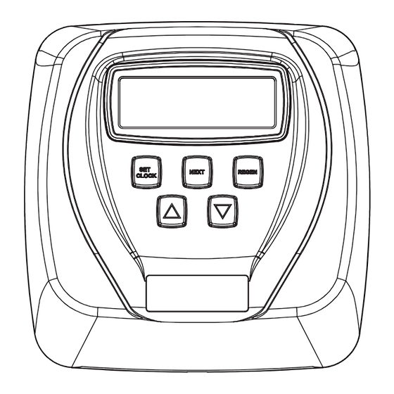
Page 14 WS1.5CI & 2LCI Man u al User Display Settings General Operation When the system is operating, one of fi ve displays may be shown. Pressing NEXT will alternate between the displays. One of the displays is always the current time of day. The second display is one of the following: days remaining or volume remaining. - Page 15 WS1.5CI & 2LCI Man u al Page 15 Set Time of Day The user can also set the time of day. Time of day should only need to be set after power outages lasting more than 24 hours, if the battery has been depleted and a power outage occurs or when daylight saving time begins or ends. If a power outage lasting more than 24 hours occurs, the time of day will fl...
- Page 16 Page 16 WS1.5CI & 2LCI Man u al Salt Remaining or Adding Salt If the Low Salt Warning was activated in the last step of OEM Softener System Setup the following screens will be viewed in the User Display. Note: The salt used per regeneration setting can be set in increments of 0.05 Kg, but the Kg REMAINING screen will round up or down to the closest whole number.
- Page 17 WS1.5CI & 2LCI Man u al Page 17 Diagnostics STEP 1D – Press ▲ and ▼ simultaneously for three seconds. If screen in step 2D does not appear STEP 1D in 5 seconds the lock on the valve is activated. To unlock press ▲, NEXT, ▼, and SET CLOCK in sequence, then press ▲...
- Page 18 Page 18 WS1.5CI & 2LCI Man u al Valve History STEP 1VH – Press ▲ and ▼ simultaneously for three seconds and release. Then press ▲ and ▼ STEP 1VH simultaneously and release. If screen in step 2VH does not appear in 5 seconds the lock on the valve is activated.
-
Page 19: Revision History
WS1.5CI & 2LCI Man u al Page 19 Revision History: 12/7/07 PAGE 6: DP Switch and alternating valve operations separated into Steps 3CS and 4CS. PAGE 18: Added Step 5VH - Error Log. 2/27/08 PAGE 9: Added “norES” to Step 8S. 5/29/08 Moved common valve drawings to V3435 WS1.5/2L Drawing and Service Manual. - Page 20 Page 20 WS1.5CI & 2LCI Man u al Form No. V3435CI – 5/29/2008...
Need help?
Do you have a question about the Water Specialist CI and is the answer not in the manual?
Questions and answers