Table of Contents
Advertisement
Quick Links
Advertisement
Table of Contents

Related Manuals for DLab SK-D3309-Pro


Summary of Contents for DLab SK-D3309-Pro
- Page 1 Shaker SK-D3309-Pro LCD Digital 3D Shaker VERSION20170329...
-
Page 2: Table Of Contents
CONTENTS Chapter 1: Working Principle ......................1 1.1 Introduction ........................1 Chapter 2: Removal and Installation of Instrument ............... 2 Removal ........................2 Main parts illustration ....................4 Replacement of master control board ................5 Replacement of motor component and photo electronic switch ......... 5 Replacement of power board component .............. -
Page 3: Chapter 1: Working Principle
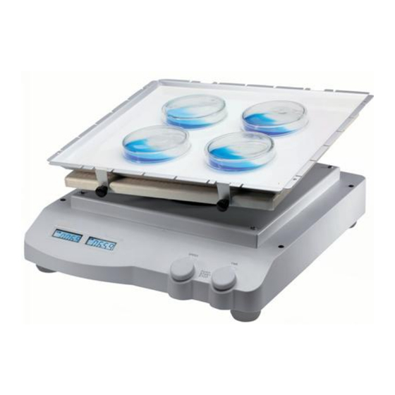
Shaker carries an object to conduct linear or circular motion at different speeds, and then mix the material. Fig. 1 is the schematic diagram of Shaker SK-D3309-Pro. There are Speed display, Time display, speed control knob, and timer knob on instrument control panel; power switch, on the side of instrument;... -
Page 4: Chapter 2: Removal And Installation Of Instrument
Chapter 2: Removal and Installation of Instrument When instrument failure occurs, first, you should conduct a failure analysis; if the failure is caused by the damage of instrument hardware, the related component must be repaired or replaced. Here are the relevant contents of the replacement and disassembly of instrument. 2.1 Removal Tool:Cross screwdriver, Diagonal Pliers, Allen key, socket spanner Step 1:... - Page 5 Step 3: Remove the 4 screws marked by red circles and keep them well; Step 4: Remove the screw marked by red circle, separate ground wire and metal plate; Step 5: Lift the Upper Guard, and pull out 3 ribbon cables marked by red circles;...
-
Page 6: Main Parts Illustration
Step 4: Lift up the Upper Guard upside as shown in the Figure, and place it on the clean desktop. 2.2 Main parts illustration... -
Page 7: Replacement Of Master Control Board
Item Spare Parts Part number Encoder 18100127 LCD Board 18101126 Power board 18100839 motor 18100830 Motor board 18800016 Master Control Board 18100197 Locking Hose 18200845 2.3 Replacement of master control board Step 1: As shown in the left figure, remove the 4 screws and keep them well, unplug the connectors then replace a new master control board, assemble in sequence. -
Page 8: Replacement Of Power Board Component
Step 2: Remove the 2 crews marked by red circles and keep them well, unplug the connector marked by green circle, then replace photo electronic switch; Note: When you replaced new photoelectronic switch, the Shaft Encoder on the motor must match with photoelectronic... -
Page 9: Replacement Of Motor Drive Board
2.6 Replacement of motor drive board As shown in the left figure, unplug connectors marked by green circle, loosen the 2 screws marked by blue circle and unplug 2 cables, remove 4 screws marked by red circle, then replace motor drive board, then assemble it in sequence.
Need help?
Do you have a question about the SK-D3309-Pro and is the answer not in the manual?
Questions and answers