
Summary of Contents for DSI DS Series
- Page 1 Operating Instructions Designed Security, Inc. - 1402 Hawthorne Street, Bastrop Texas 78602 Toll Free 800-272-3555 | 512-321-4426 | Fax: 512-321-9181 www.dsigo.com | sales@dsigo.com INS-DSMG-200702...
- Page 2 Designed Security, Inc. - 1402 Hawthorne Street, Bastrop Texas 78602 Toll Free 800-272-3555 | 512-321-4426 | Fax: 512-321-9181 www.dsigo.com | sales@dsigo.com INS-DSMG-200702...
-
Page 3: Table Of Contents
Contents General..................7 Safety ..................12 Technical data ..............19 Design and function.............22 Assembly and installation...........24 Designed Security, Inc. - 1402 Hawthorne Street, Bastrop Texas 78602 Toll Free 800-272-3555 | 512-321-4426 | Fax: 512-321-9181 www.dsigo.com | sales@dsigo.com INS-DSMG-200702... - Page 4 Contents Electrical connection ............33 Assemble MPS column............38 Commissioning ..............40 Function description............45 10 Setting parameters – "MPS-Diag" ....49 Designed Security, Inc. - 1402 Hawthorne Street, Bastrop Texas 78602 Toll Free 800-272-3555 | 512-321-4426 | Fax: 512-321-9181 www.dsigo.com | sales@dsigo.com INS-DSMG-200702...
- Page 5 Contents 11 Maintenance .................69 12 Malfunctions .................72 13 Spare parts ................75 14 Decommissioning and disposal .........76 Index....................79 Designed Security, Inc. - 1402 Hawthorne Street, Bastrop Texas 78602 Toll Free 800-272-3555 | 512-321-4426 | Fax: 512-321-9181 www.dsigo.com | sales@dsigo.com INS-DSMG-200702...
- Page 6 Designed Security, Inc. - 1402 Hawthorne Street, Bastrop Texas 78602 Toll Free 800-272-3555 | 512-321-4426 | Fax: 512-321-9181 www.dsigo.com | sales@dsigo.com INS-DSMG-200702...
- Page 7 General General Information regarding the operating instructions Designed Security, Inc. - 1402 Hawthorne Street, Bastrop Texas 78602 Toll Free 800-272-3555 | 512-321-4426 | Fax: 512-321-9181 www.dsigo.com | sales@dsigo.com INS-DSMG-200702...
- Page 8 General Pictogram explanation Warning notes DANGER WARNING CAUTION NOTICE Hints and recommendations NOTE! … highlights useful hints and recommendations as well as information for an efficient and trouble-free operation. Designed Security, Inc. - 1402 Hawthorne Street, Bastrop Texas 78602 Toll Free 800-272-3555 | 512-321-4426 | Fax: 512-321-9181 www.dsigo.com | sales@dsigo.com INS-DSMG-200702...
- Page 9 General Limitation of liability Copyright protection NOTE! Content details, texts, drawings, pictures and other illustrations are protected by copyright and are subject to industrial property rights. Any improper use shall be liable to prosecution. Designed Security, Inc. - 1402 Hawthorne Street, Bastrop Texas 78602 Toll Free 800-272-3555 | 512-321-4426 | Fax: 512-321-9181 www.dsigo.com | sales@dsigo.com INS-DSMG-200702...
- Page 10 General Scope of delivery The scope of delivery comprises: with integrated drive and integrated control units MBC and MMC 1 x Locking element 1 x USB-extension 1 x Drilling jig 1 x Fastening kit (only within Europe) 1 x Software on data carrier Supplied documentation: 1 x Operating instructions 1 x Electric circuit diagram...
-
Page 11: General
General Customer service NOTE! In order to enable fast handling note the data of the type plate such as type code, serial number, etc. before calling. Environmental protection NOTICE Danger for the environment by improper disposal of components or the pedestrian barrier! Designed Security, Inc. - Page 12 Safety Safety Intended use WARNING Non-intended use is dangerous! Designed Security, Inc. - 1402 Hawthorne Street, Bastrop Texas 78602 Toll Free 800-272-3555 | 512-321-4426 | Fax: 512-321-9181 www.dsigo.com | sales@dsigo.com INS-DSMG-200702...
- Page 13 Safety Operator's Responsibility Changes and modifications Designed Security, Inc. - 1402 Hawthorne Street, Bastrop Texas 78602 Toll Free 800-272-3555 | 512-321-4426 | Fax: 512-321-9181 www.dsigo.com | sales@dsigo.com INS-DSMG-200702...
- Page 14 Safety Specialists and operating personnel 2.4.1 Requirements WARNING Risk of injury in case of inadequate qualification! Instructed people Specialised staff Electrical specialists Designed Security, Inc. - 1402 Hawthorne Street, Bastrop Texas 78602 Toll Free 800-272-3555 | 512-321-4426 | Fax: 512-321-9181 www.dsigo.com | sales@dsigo.com INS-DSMG-200702...
- Page 15 Safety Personal protective equipment Occupational safety and special dangers 2.6.1 Danger pictograms on the pedestrian barrier Electric voltage DANGER Mortal danger by electric voltage! Danger of crushing WARNING Danger of crushing! Designed Security, Inc. - 1402 Hawthorne Street, Bastrop Texas 78602 Toll Free 800-272-3555 | 512-321-4426 | Fax: 512-321-9181 www.dsigo.com | sales@dsigo.com INS-DSMG-200702...
-
Page 16: Safety
Safety 2.6.2 Hazard notes and occupational safety Electric voltage DANGER Mortal danger by electric voltage! Electric voltage – DANGER missing safety installations Mortal danger by electric voltage! Designed Security, Inc. - 1402 Hawthorne Street, Bastrop Texas 78602 Toll Free 800-272-3555 | 512-321-4426 | Fax: 512-321-9181 www.dsigo.com | sales@dsigo.com INS-DSMG-200702... - Page 17 Safety Improper transport WARNING Danger by falling down or tilting of a pedestrian barrier! Heavy weight WARNING Risk of injury when lifting heavy objects alone! Insufficient fixing WARNING Risk of injury at insufficient fixing! Designed Security, Inc. - 1402 Hawthorne Street, Bastrop Texas 78602 Toll Free 800-272-3555 | 512-321-4426 | Fax: 512-321-9181 www.dsigo.com | sales@dsigo.com INS-DSMG-200702...
- Page 18 Safety Inadmissible operation WARNING Risk of injury at inadmissible operation! Sharp edges and spiky corners CAUTION Risk of injury on edges and corners! Signposting CAUTION Risk of injury by illegible symbols! Designed Security, Inc. - 1402 Hawthorne Street, Bastrop Texas 78602 Toll Free 800-272-3555 | 512-321-4426 | Fax: 512-321-9181 www.dsigo.com | sales@dsigo.com INS-DSMG-200702...
- Page 19 Technical data Technical data Dimensions 3.1.1 Æ Fig. 1: Dimensions for in b Safety distances to avoid crushing Total width Bracket length, Standard: 1090mm , max. 1800 mm Designed Security, Inc. - 1402 Hawthorne Street, Bastrop Texas 78602 Toll Free 800-272-3555 | 512-321-4426 | Fax: 512-321-9181 www.dsigo.com | sales@dsigo.com INS-DSMG-200702...
- Page 20 Technical data 3.1.2 in wing version Æ Fig. 2: Dimensions for in wing version Safety distances to avoid crushing Floor distance: 200mm at wing height 800 170mm at wing heights 1030mm and 1330 mm Electrical connection Designation Unit 230 V 50 Hz 115 V 60 Hz 1) The values are without heating.
- Page 21 Designed Security, Inc. - 1402 Hawthorne Street, Bastrop Texas 78602 Toll Free 800-272-3555 | 512-321-4426 | Fax: 512-321-9181 www.dsigo.com | sales@dsigo.com INS-DSMG-200702...
- Page 22 Designed Security, Inc. - 1402 Hawthorne Street, Bastrop Texas 78602 Toll Free 800-272-3555 | 512-321-4426 | Fax: 512-321-9181 www.dsigo.com | sales@dsigo.com INS-DSMG-200702...
-
Page 23: Technical Data
Designed Security, Inc. - 1402 Hawthorne Street, Bastrop Texas 78602 Toll Free 800-272-3555 | 512-321-4426 | Fax: 512-321-9181 www.dsigo.com | sales@dsigo.com INS-DSMG-200702... - Page 24 Designed Security, Inc. - 1402 Hawthorne Street, Bastrop Texas 78602 Toll Free 800-272-3555 | 512-321-4426 | Fax: 512-321-9181 www.dsigo.com | sales@dsigo.com INS-DSMG-200702...
- Page 25 Technical data Operating conditions Designation Unit Table 2: Operating conditions Weight Designation Unit Table 3: Weight Performance data Designation Unit Table 4: Performance data Designed Security, Inc. - 1402 Hawthorne Street, Bastrop Texas 78602 Toll Free 800-272-3555 | 512-321-4426 | Fax: 512-321-9181 www.dsigo.com | sales@dsigo.com INS-DSMG-200702...
-
Page 26: Design And Function
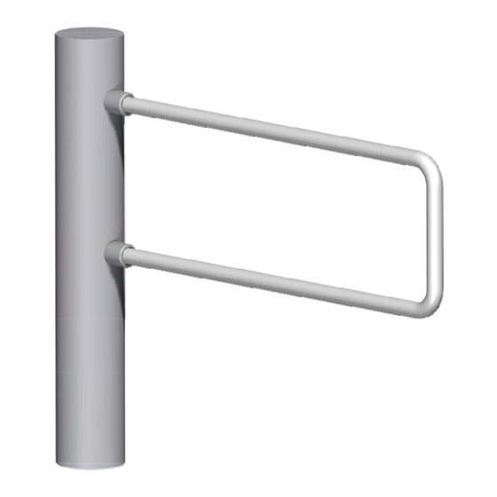
Design and function Design and function Design Fig. 3: Structure of components Countersunk screw M6 x16 Disc/screws M5 x 16 Isolation sleeve Cover Top cover disc Locking element in bracket version O-Ring Threaded pin Countersunk screws M8 x 20 Countersunk screw M6 Outer tube Holder for locking element Edge profile (with drive, control units, transformer) - Page 27 Design and function Definition left and right Fig. 4: Version "Left " Fig. 5: Version "Right " Function Designed Security, Inc. - 1402 Hawthorne Street, Bastrop Texas 78602 Toll Free 800-272-3555 | 512-321-4426 | Fax: 512-321-9181 www.dsigo.com | sales@dsigo.com INS-DSMG-200702...
-
Page 28: Assembly And Installation
Assembly and installation Assembly and installation Safety General WARNING Danger by inappropriate installation! Improper transport WARNING Danger by falling down or tilting of a pedestrian barrier! Designed Security, Inc. - 1402 Hawthorne Street, Bastrop Texas 78602 Toll Free 800-272-3555 | 512-321-4426 | Fax: 512-321-9181 www.dsigo.com | sales@dsigo.com INS-DSMG-200702... - Page 29 Assembly and installation Heavy weight WARNING Risk of injury when lifting heavy objects alone! Improper transport NOTICE The pedestrian barrier can be damaged by improper transport! Personal protective equipment Designed Security, Inc. - 1402 Hawthorne Street, Bastrop Texas 78602 Toll Free 800-272-3555 | 512-321-4426 | Fax: 512-321-9181 www.dsigo.com | sales@dsigo.com INS-DSMG-200702...
- Page 30 Assembly and installation Requirements for assembly Foundation and empty conduits Note! To provide trouble-free operation use separate conduits for data cables and mains cables. The functional safety of the pedestrian barrier hinges on the accuracy of the foundation. Foundation Empty conduits Drilling jig Designed Security, Inc.
- Page 31 Assembly and installation 5.3.1 Foundation plan Fig. 6: Foundation plan Recessed head screw M8 x 80 Spring washer Disc Tie anchor with inner thread M8 Empty conduits Designed Security, Inc. - 1402 Hawthorne Street, Bastrop Texas 78602 Toll Free 800-272-3555 | 512-321-4426 | Fax: 512-321-9181 www.dsigo.com | sales@dsigo.com INS-DSMG-200702...
- Page 32 Assembly and installation Mounting the Fig. 7: Mounting the Countersunk screw M6 x16 Disc/screws M5 x 16 Isolation sleeve Cover Top cover disc Locking element in bracket version O-Ring Threaded pin Countersunk screws M8 x 20 Countersunk screw M6 Outer tube Holder for locking element Edge profile (with drive, control units, transformer) Locking element in wing version...
- Page 33 Assembly and installation 5.4.1 Mounting the on the foundation NOTE! is delivered completely. has to be partially disassembled before it can be mounted. The foundation has set to the adequate hardness. Foundation and empty conduits must be tested prior to commencing assembly. is fastened with 3 tie anchors on the foundation.
- Page 34 Assembly and installation Fig. 9 and 10: Countersunk screw and cover disc 5.4.2 Disassemble Fig. 11: Cover disc Fig. 12: Countersunk screws Designed Security, Inc. - 1402 Hawthorne Street, Bastrop Texas 78602 Toll Free 800-272-3555 | 512-321-4426 | Fax: 512-321-9181 www.dsigo.com | sales@dsigo.com INS-DSMG-200702...
- Page 35 Assembly and installation Fig. 13: Outer tube with Fig. 14: Cover locking element Designed Security, Inc. - 1402 Hawthorne Street, Bastrop Texas 78602 Toll Free 800-272-3555 | 512-321-4426 | Fax: 512-321-9181 www.dsigo.com | sales@dsigo.com INS-DSMG-200702...
- Page 36 Assembly and installation Fig. 15: MPS floor attachment MPS edge profile Screws M8, spring ring, washer (each 3 x) NOTE! Observe curing time for the resin cartridge: >20 °C 10 min 20 min 10 °C to 20 °C 0 °C to -10 °C –5 °C to 0 °C Designed Security, Inc.
-
Page 37: Electrical Connection
Electrical connection Electrical connection Safety General WARNING Danger by inappropriate installation! Electric voltage DANGER Mortal danger by electric voltage! Designed Security, Inc. - 1402 Hawthorne Street, Bastrop Texas 78602 Toll Free 800-272-3555 | 512-321-4426 | Fax: 512-321-9181 www.dsigo.com | sales@dsigo.com INS-DSMG-200702... - Page 38 Electrical connection Electric voltage – DANGER missing safety installations Mortal danger by electric voltage! The safety installations that are required according to regional and local regulations must be provided by the customer. Usually these are: – Residual current device (RCD) –...
- Page 39 Electrical connection Connecting the power supply Fig. 16: Power supply connection terminals Terminals L, N, PE 2-pin main switch Connect control lines to MBC-111 Designed Security, Inc. - 1402 Hawthorne Street, Bastrop Texas 78602 Toll Free 800-272-3555 | 512-321-4426 | Fax: 512-321-9181 www.dsigo.com | sales@dsigo.com INS-DSMG-200702...
- Page 40 Electrical connection 6.3.1 Digital inputs Input Function Description Table 5: Digital inputs Designed Security, Inc. - 1402 Hawthorne Street, Bastrop Texas 78602 Toll Free 800-272-3555 | 512-321-4426 | Fax: 512-321-9181 www.dsigo.com | sales@dsigo.com INS-DSMG-200702...
- Page 41 Electrical connection 6.3.2 Relay outputs Relay output Function Description Table 6: Relay outputs NOTE! Voltage outage is indicated at the global error output; therefore, relay 1 is operated invertedly. This means that the relay is closed as long as there is no error. As soon as one the global errors described above occurs, the relay falls off.
-
Page 42: Assemble Mps Column
Assemble MPS column Assemble MPS column Danger of crushing CAUTION Danger of crushing! Mounting the locking element Fig. 17: Alignment of stop screw Designed Security, Inc. - 1402 Hawthorne Street, Bastrop Texas 78602 Toll Free 800-272-3555 | 512-321-4426 | Fax: 512-321-9181 www.dsigo.com | sales@dsigo.com INS-DSMG-200702... - Page 43 Assemble MPS column Adjusting the mechanical end stops Fig. 18: Adjusting the right end stop Fig. 19: Adjusting the left end stop Designed Security, Inc. - 1402 Hawthorne Street, Bastrop Texas 78602 Toll Free 800-272-3555 | 512-321-4426 | Fax: 512-321-9181 www.dsigo.com | sales@dsigo.com INS-DSMG-200702...
-
Page 44: Commissioning
Commissioning Commissioning Safety General WARNING Danger by inappropriate start-up and operation! DANGER Electric voltage Mortal danger by electric voltage! Personal protective equipment Designed Security, Inc. - 1402 Hawthorne Street, Bastrop Texas 78602 Toll Free 800-272-3555 | 512-321-4426 | Fax: 512-321-9181 www.dsigo.com | sales@dsigo.com INS-DSMG-200702... - Page 45 Commissioning Initial commissioning Free movement path Initial commissioning NOTE! Functions and parameters can be changed via "MPS-Diag". See page 49, chapter 10. Designed Security, Inc. - 1402 Hawthorne Street, Bastrop Texas 78602 Toll Free 800-272-3555 | 512-321-4426 | Fax: 512-321-9181 www.dsigo.com | sales@dsigo.com INS-DSMG-200702...
- Page 46 Commissioning CAN bus addressing and termination Function DIP switch MBC-111 MMC-120 Table 7: Setting of the DIP switches Fig. 20: DIP switch Fig. 21: DIP switch CAN MBC-111 CAN MMC-120 NOTE! Wrong settings for the DIP switch can lead to the swing doors not going into operation or to malfunctions during operation.
- Page 47 Commissioning Setting the home position and hold-open time via button Fig. 22: Button for setting the home position and hold-open time 8.4.1 Setting the home position Free movement path NOTE! If you do not push the button again within the next 10 seconds, the process will be cancelled.
- Page 48 Commissioning 8.4.2 Set hold-open time NOTE! If you do not push the button three times within 5 seconds, the process will be cancelled. The original hold-open time remains valid. The buzzer emits a signal at 2 Hz twice. NOTE! If you do not push the button for 5 seconds, the number of pushes of the button is assumed for the new hold-open time value.
-
Page 49: Function Description
Function description Function description Power-off state Start-up routine Homing Designed Security, Inc. - 1402 Hawthorne Street, Bastrop Texas 78602 Toll Free 800-272-3555 | 512-321-4426 | Fax: 512-321-9181 www.dsigo.com | sales@dsigo.com INS-DSMG-200702... - Page 50 Function description Fig. 23: Homing at a left and right Regular movement process Designed Security, Inc. - 1402 Hawthorne Street, Bastrop Texas 78602 Toll Free 800-272-3555 | 512-321-4426 | Fax: 512-321-9181 www.dsigo.com | sales@dsigo.com INS-DSMG-200702...
- Page 51 Function description Special cases within motion sequence 9.5.1 Obstacle recognition during the movement 9.5.2 Turning back during the movement Option "Brake on if vandalism" is activated Option "Brake always off" is activated Designed Security, Inc. - 1402 Hawthorne Street, Bastrop Texas 78602 Toll Free 800-272-3555 | 512-321-4426 | Fax: 512-321-9181 www.dsigo.com | sales@dsigo.com INS-DSMG-200702...
- Page 52 Function description 9.5.3 Attempted vandalism The behavior can be set via the parameter "Brake options". Refer to page 56, chapter 10.4.2. Option "Brake on if vandalism" is Once an attempt is made to move the locking element from the activated home position, the brake is activated.
-
Page 53: Setting
Setting parameters – "MPS-Diag" 10 Setting parameters – "MPS-Diag" Fig. 24: MPS-Diag program Designed Security, Inc. - 1402 Hawthorne Street, Bastrop Texas 78602 Toll Free 800-272-3555 | 512-321-4426 | Fax: 512-321-9181 www.dsigo.com | sales@dsigo.com INS-DSMG-200702... - Page 54 Setting parameters – "MPS-Diag" 10.1 Driver installation under Windows 7 Driver installation possibilities NOTE! For more information on the driver, see http://ftdichip.com/Support/Documents/ AppNotes.htm 10.1.1 Automatic driver installation via setup assistant Using the driver from the internet Designed Security, Inc. - 1402 Hawthorne Street, Bastrop Texas 78602 Toll Free 800-272-3555 | 512-321-4426 | Fax: 512-321-9181 www.dsigo.com | sales@dsigo.com INS-DSMG-200702...
- Page 55 Setting parameters – "MPS-Diag" Use included driver 10.1.2 Manual driver installation Using the driver from the internet Use included driver Designed Security, Inc. - 1402 Hawthorne Street, Bastrop Texas 78602 Toll Free 800-272-3555 | 512-321-4426 | Fax: 512-321-9181 www.dsigo.com | sales@dsigo.com INS-DSMG-200702...
- Page 56 Setting parameters – "MPS-Diag" 10.1.3 Enter the port number in the program "MPS-Diag". Successful driver installation Fig. 25: Entry "USB serial port with port number" (here COM9) at successful installation Designed Security, Inc. - 1402 Hawthorne Street, Bastrop Texas 78602 Toll Free 800-272-3555 | 512-321-4426 | Fax: 512-321-9181 www.dsigo.com | sales@dsigo.com INS-DSMG-200702...
- Page 57 Setting parameters – "MPS-Diag" Failed driver installation Fig. 26: Missing port number" if the installation has failed 10.2 Connect laptop to control device MB-111 Fig. 27: Connection for USB plug with extension Designed Security, Inc. - 1402 Hawthorne Street, Bastrop Texas 78602 Toll Free 800-272-3555 | 512-321-4426 | Fax: 512-321-9181 www.dsigo.com | sales@dsigo.com INS-DSMG-200702...
- Page 58 Setting parameters – "MPS-Diag" 10.3 Using the MPS-Diag program Designed Security, Inc. - 1402 Hawthorne Street, Bastrop Texas 78602 Toll Free 800-272-3555 | 512-321-4426 | Fax: 512-321-9181 www.dsigo.com | sales@dsigo.com INS-DSMG-200702...
- Page 59 Setting parameters – "MPS-Diag" 10.4 Function and parameter settings 10.4.1 Version left / right Fig. 28: Explanation on version "Right" and "Left", here the directions for the left are presented Designed Security, Inc. - 1402 Hawthorne Street, Bastrop Texas 78602 Toll Free 800-272-3555 | 512-321-4426 | Fax: 512-321-9181 www.dsigo.com | sales@dsigo.com INS-DSMG-200702...
- Page 60 Setting parameters – "MPS-Diag" Fig. 29: Explanation on version "Right" and "Left", here the directions for the right are presented 10.4.2 Brake activated / not activated Fig.30: Possible settings for the brake Designed Security, Inc. - 1402 Hawthorne Street, Bastrop Texas 78602 Toll Free 800-272-3555 | 512-321-4426 | Fax: 512-321-9181 www.dsigo.com | sales@dsigo.com INS-DSMG-200702...
- Page 61 Setting parameters – "MPS-Diag" 10.4.3 Select size of the locking element Fig. 31: Select length of the locking bracket 10.4.4 Select reset source Fig. 32: Select reset source 10.4.5 Stalled behavior (Behavior when obstruction detected) Fig. 33: Stalled behavior (behavior when obstruction detected) Designed Security, Inc.
- Page 62 Setting parameters – "MPS-Diag" 10.4.6 Set hold-open time Fig. 34: Set hold-open time 10.4.7 Set speed Fig. 35: Set speed 10.4.8 Heating active while standing Fig. 36: Switch on standing heating. Designed Security, Inc. - 1402 Hawthorne Street, Bastrop Texas 78602 Toll Free 800-272-3555 | 512-321-4426 | Fax: 512-321-9181 www.dsigo.com | sales@dsigo.com INS-DSMG-200702...
- Page 63 Setting parameters – "MPS-Diag" 10.4.9 Teaching the three possible positions Fig. 37: Activate screen mask for adjusting the target positions Fig. 38: Setting the target positions Fig. 39: Perform homing Designed Security, Inc. - 1402 Hawthorne Street, Bastrop Texas 78602 Toll Free 800-272-3555 | 512-321-4426 | Fax: 512-321-9181 www.dsigo.com | sales@dsigo.com INS-DSMG-200702...
- Page 64 Setting parameters – "MPS-Diag" Fig. :40 Adjust home position Fig. 41: Adjust "left position" Fig. 42: Adjust "right position" Designed Security, Inc. - 1402 Hawthorne Street, Bastrop Texas 78602 Toll Free 800-272-3555 | 512-321-4426 | Fax: 512-321-9181 www.dsigo.com | sales@dsigo.com INS-DSMG-200702...
- Page 65 Setting parameters – "MPS-Diag" Fig. :43 Reset control MBC 10.4.10 Reset all parameters to factory settings Fig. 44: Menu "Parameter" Fig. 45: Select menu item "Restore all parameters to factory settings" Designed Security, Inc. - 1402 Hawthorne Street, Bastrop Texas 78602 Toll Free 800-272-3555 | 512-321-4426 | Fax: 512-321-9181 www.dsigo.com | sales@dsigo.com INS-DSMG-200702...
- Page 66 Setting parameters – "MPS-Diag" Fig. 46: Safety confirmation 10.5 Firmware download Fig. 47: Menu "View" Designed Security, Inc. - 1402 Hawthorne Street, Bastrop Texas 78602 Toll Free 800-272-3555 | 512-321-4426 | Fax: 512-321-9181 www.dsigo.com | sales@dsigo.com INS-DSMG-200702...
- Page 67 Setting parameters – "MPS-Diag" Fig. 48: Menu "Firmware update" (here: no communication) Designed Security, Inc. - 1402 Hawthorne Street, Bastrop Texas 78602 Toll Free 800-272-3555 | 512-321-4426 | Fax: 512-321-9181 www.dsigo.com | sales@dsigo.com INS-DSMG-200702...
- Page 68 Setting parameters – "MPS-Diag" 10.5.1 Firmware download using a ".mcp file" Fig. 49: Button "Download Firmware" Fig. 50: Download progress 10.5.2 Firmware download using an ".s file" Fig. 51: File type selection Designed Security, Inc. - 1402 Hawthorne Street, Bastrop Texas 78602 Toll Free 800-272-3555 | 512-321-4426 | Fax: 512-321-9181 www.dsigo.com | sales@dsigo.com INS-DSMG-200702...
- Page 69 Setting parameters – "MPS-Diag" Fig. 52: Control selection Fig. 53: Dialoge "Confirmation" Fig. 54: Dialog "Information" Designed Security, Inc. - 1402 Hawthorne Street, Bastrop Texas 78602 Toll Free 800-272-3555 | 512-321-4426 | Fax: 512-321-9181 www.dsigo.com | sales@dsigo.com INS-DSMG-200702...
- Page 70 Setting parameters – "MPS-Diag" 10.6 Download between MBC-111 and MMC-120 Fig. 55: Programming via the MPS-Diag Designed Security, Inc. - 1402 Hawthorne Street, Bastrop Texas 78602 Toll Free 800-272-3555 | 512-321-4426 | Fax: 512-321-9181 www.dsigo.com | sales@dsigo.com INS-DSMG-200702...
- Page 71 Setting parameters – "MPS-Diag" 10.7 Reading errors Fig. 56: Reading MBC-111 and MMC-120 errors Designed Security, Inc. - 1402 Hawthorne Street, Bastrop Texas 78602 Toll Free 800-272-3555 | 512-321-4426 | Fax: 512-321-9181 www.dsigo.com | sales@dsigo.com INS-DSMG-200702...
- Page 72 Setting parameters – "MPS-Diag" 10.8 Status request NOTE! The states of the DIP switches for parametrisation of hte CAN bus cannot be read via MPS-Diag. This is only possible directly at the control. Therefore, these settings must be checked before the MPS is assembled! Fig.
-
Page 73: Maintenance
Maintenance 11 Maintenance 11.1 Safety General WARNING Danger by inappropriate maintenance! Electric voltage DANGER Mortal danger by electric voltage! Designed Security, Inc. - 1402 Hawthorne Street, Bastrop Texas 78602 Toll Free 800-272-3555 | 512-321-4426 | Fax: 512-321-9181 www.dsigo.com | sales@dsigo.com INS-DSMG-200702... - Page 74 Maintenance Personal protective equipment 11.2 Cleaning Aggressive cleaning aids and NOTICE substances Unit damage possible! Designed Security, Inc. - 1402 Hawthorne Street, Bastrop Texas 78602 Toll Free 800-272-3555 | 512-321-4426 | Fax: 512-321-9181 www.dsigo.com | sales@dsigo.com INS-DSMG-200702...
- Page 75 Maintenance 11.3 Maintenance schedule Interval Maintenance work To be carried out by Table 8: Maintenance schedule Designed Security, Inc. - 1402 Hawthorne Street, Bastrop Texas 78602 Toll Free 800-272-3555 | 512-321-4426 | Fax: 512-321-9181 www.dsigo.com | sales@dsigo.com INS-DSMG-200702...
-
Page 76: Malfunctions
Malfunctions 12 Malfunctions 12.1 Safety This chapter describes possible causes of malfunctions and trouble shooting tasks. Contact the manufacturer in case of malfunctions that cannot be repaired by means of the following information. (For service address, Refer to page 2) General WARNING Danger of injury from inappropriate... - Page 77 Malfunctions 12.2 Error codes on the logic controller MBC-111 NOTE! Additionally, dispose of the "MPS Diag" for further diagnostics. Here you can read out the errors via the serial interface. See page 67, chapter 10.7 Display error codes Examples Error code Fault description Automatic reset Designed Security, Inc.
- Page 78 Malfunctions Error code Fault description Automatic reset Error when initialising CAN protocol stack Error when initialising CAN bus CAN servo address fault Error download of controller parameters for the MMC-120 Reserved Error I²C-EEPROM Software fault 70 to 7F Error when downloading the MMC-120 firmware Table 9: Error code Self-resetting errors are displayed for no more than 20 seconds if the error is no longer pending.
-
Page 79: Spare Parts
Spare parts 13 Spare parts WARNING Risk of injury by incorrect spare parts! Designed Security, Inc. - 1402 Hawthorne Street, Bastrop Texas 78602 Toll Free 800-272-3555 | 512-321-4426 | Fax: 512-321-9181 www.dsigo.com | sales@dsigo.com INS-DSMG-200702... -
Page 80: Decommissioning And Disposal
Decommissioning and disposal 14 Decommissioning and disposal A pedestrian barrier that is no longer usable should not be recycled as a complete unit, but disassembled into individual components and recycled according to material types. Non-recyclable materials have to be disposed of in an environmental-friendly manner. Decommissioning, disassembly and disposal of the pedestrian barrier may only be carried out by specialised staff. - Page 81 Designed Security, Inc. - 1402 Hawthorne Street, Bastrop Texas 78602 Toll Free 800-272-3555 | 512-321-4426 | Fax: 512-321-9181 www.dsigo.com | sales@dsigo.com INS-DSMG-200702...
- Page 82 Appendix Appendix 1 .1 Electric circuit diagram Designed Security, Inc. - 1402 Hawthorne Street, Bastrop Texas 78602 Toll Free 800-272-3555 | 512-321-4426 | Fax: 512-321-9181 www.dsigo.com | sales@dsigo.com INS-DSMG-200702...
-
Page 83: Index
Index Index Designed Security, Inc. - 1402 Hawthorne Street, Bastrop Texas 78602 Toll Free 800-272-3555 | 512-321-4426 | Fax: 512-321-9181 www.dsigo.com | sales@dsigo.com INS-DSMG-200702... - Page 84 Index ........19 Safety..............12 Wing version........... 20 Assembly and installation....... 24 Commissioning..........40 Electrical connection ........33 Termination ............42 Maintenance........... 69 Malfunctions ........... 72 Versions ............. 23 Scope of delivery ..........10 Setting Hold-open time via the button ......44 Warning notes ............
- Page 85 Designed Security, Inc. - 1402 Hawthorne Street, Bastrop Texas 78602 Toll Free 800-272-3555 | 512-321-4426 | Fax: 512-321-9181 www.dsigo.com | sales@dsigo.com INS-DSMG-200702...
- Page 86 Tel.: Fax: e-mail: Designed Security, Inc. - 1402 Hawthorne Street, Bastrop Texas 78602 Toll Free 800-272-3555 | 512-321-4426 | Fax: 512-321-9181 www.dsigo.com | sales@dsigo.com INS-DSMG-200702...
Need help?
Do you have a question about the DS Series and is the answer not in the manual?
Questions and answers