
Summary of Contents for Velleman HIGH-Q Velleman-Kit K3400
- Page 1 Total solder points: 198 Difficulty level: beginner 1 advanced DUAL ELECTRONIC DICE K3400 ILLUSTRATED ASSEMBLY MANUAL H3400IP-1...
- Page 3 Features & Specifications Features: Two independent dice. Use a single or both dice at the same time. Display auto shut-off saves battery power. Low power consumption. Specifications: Power supply : 8-12VDC or 6VAC. Idle power consumption : 1mA. Power consumption both dice on : 60mA. PCB dimensions: 76 x 70mm (3.0"...
- Page 4 Assembly hints 1. Assembly (Skipping this can lead to troubles ! ) Ok, so we have your attention. These hints will help you to make this project successful. Read them carefully. 1.1 Make sure you have the right tools: • A good quality soldering iron (25-40W) with a small tip.
- Page 5 REMOVE THEM FROM THE TAPE ONE AT A TIME ! AXIAL COMPONENTS ARE TAPED IN THE CORRECT MOUNTING SEQUENCE ! You will find the colour code for the resistances and the LEDs in the HALG (general manual) and on our website: http://www.velleman.be/common/service.aspx...
- Page 6 Construction R3 : 47K (4 - 7 - 3 - B) R30 : 680 (6 - 8 - 1 - B) 1. Jumpers R4 : 47K (4 - 7 - 3 - B) R31 : 680 (6 - 8 - 1 - B) R5 : 47K (4 - 7 - 3 - B) J : 2x...
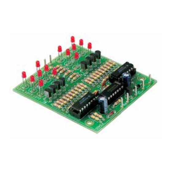
- Page 7 Construction LD13 : 3mm red 6. Transistors 8. Electrolytic capacitors. LD14 : 3mm red Watch the polarity! T1 : BC547B T2 : BC547B Pay attention to the polarity! T3 : BC547B C3 : 100µF As to the height of the leds, T4 : BC547B C4 : 100µF take into account the housing...
-
Page 8: Connection & Test
Connection & test 11. Connection & test The push button (single pole normally open contact) has to be connected to the points PB. Display selection is done by connecting VD1 respectively VD2 to VD. You can make these connections permanent, or use a bipolar three position slide switch as shown in the connections diagram. -
Page 9: Connection Example
Connection example 12. Connection example Battery USE A SLIDE SWITCH (ON OFF ON) - Page 10 Schematic diagram 13. Schematic diagram.
- Page 11 14. PCB...
- Page 12 VELLEMAN Components NV Legen Heirweg 33 9890 Gavere Belgium Europe www.velleman.be www.velleman-kit.com Modifications and typographical errors reserved © Velleman Components nv. H3400IP - 2004 - ED1 5 4 1 0 3 2 9 3 2 4 6 1 2...
Need help?
Do you have a question about the HIGH-Q Velleman-Kit K3400 and is the answer not in the manual?
Questions and answers