
Summary of Contents for schmersal USP-PI
- Page 1 Parallel Interface USP-PI Parallel interface USP-PI Bedienungsanleitung Instruction manual...
- Page 2 Deutsch Seiten 3 – 30 English Pages 31 – 58...
-
Page 3: Table Of Contents
Ausgänge setzen ........26 Fehlermeldungen des USP-PI ......26 Maßnahmen zur Einrichtung und Inbetriebnahme . -
Page 4: Einleitung
Allgemeine Hinweise Das Parallel-Interface USP-PI wurde nach dem Stand der Technik gebaut. Diese Bedienungsanlei- tung ist von allen Personen zu beachten, die mit dem USP-PI arbeiten oder dieses montieren. Es ist zwingend notwendig, diese Bedienungsanleitung den zuständigen Monteuren oder dem In- standhaltungspersonal jederzeit zugänglich zu machen. -
Page 5: Zu Ihrer Persönlichen Sicherheit
Zu Ihrer persönlichen Sicherheit Diese Bedienungsanleitung vermittelt Ihnen wichtige Sicherheitshinweise und Informatio- nen, die zur einwandfreien Inbetriebnahme des Parallel-Interface USP-PI erforderlich sind. Lesen Sie diese Bedienungsanleitung vollständig und aufmerksam. • Der Monteur muß mit den grundlegenden Vorschriften über Arbeitssicherheit und Unfallverhü- tung vertraut und in die Handhabung von Förderanlagen eingewiesen sein. -
Page 6: Montage Der Programmierbaren Einheit Usp-Pi
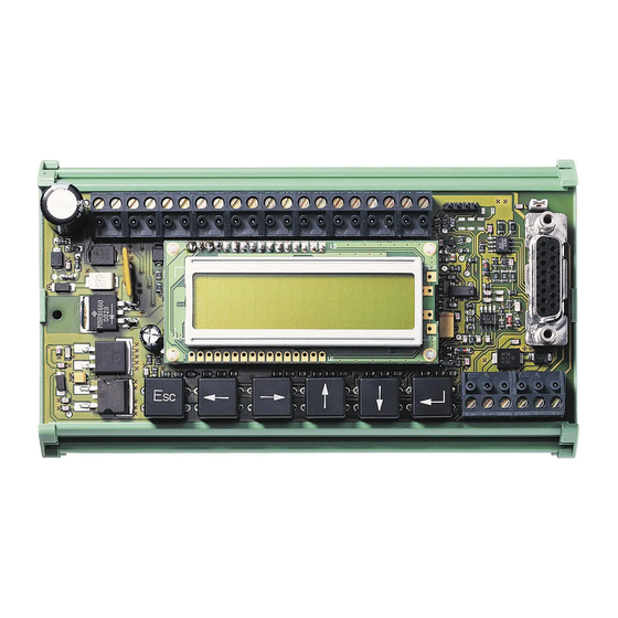
Das USP-PI ist gemäß der Schutzart IP 00 konstruiert und somit in einem geschlossenen Schaltschrank zu installieren. Setzen Sie das USP-PI an einen freien und geeigneten Platz auf die Normschiene im Schaltschrank auf, an dem es vor Verschmutzung geschützt ist. Das Profil ist so ausgeführt, dass Sie die Platine einfach auf die Schiene aufklipsen können. -
Page 7: Funktion Der Programmierbaren Einheit Usp-Pi
Der Kommunikationsbaustein USP-PI dient zur Eingabe und Veränderung aller notwendigen Parameter, die zur Berechnung der Schaltpunkte einer Schachtkopie notwendig sind. Der Bau- stein USP-PI erlaubt zusätzlich, neben der manuellen Eingabe der Schaltpunkte, ein Erfassen der Bündigwerte mittels eines Lerntasters und einer damit verbundenen Lernfahrt. Als Grund- lage zur Berechnung der Schaltpunkte dient ein Schachtprofil. -
Page 8: Die Menüfunktionen Des Usp-Pi
Parallel Interface USP-PI Die Menüfunktionen des USP-PI Der Kommunikationsbaustein USP-PI bietet Ihnen eine Reihe von Funktionen, die es er- möglichen, die Berechnungen der Schaltpunkte auf ihr Schachtprofil genauestens anzu- passen. Die Menüfunktionen sind in Menüs und Untermenüs gegliedert, auf die Sie durch Betätigen der Taster zugreifen können. -
Page 9: Die Struktur Der Menüfunktionen
Parallel Interface USP-PI Die Struktur der Menüfunktionen Alle Parametereinstellungen und Anzeigen des USP-PI sind in der unten aufgeführten Menüstruktur hinter- legt. Die Texte im Display können mehrsprachig angezeigt werden. Alle Positionsangaben erfolgen in mm, Geschwindigkeiten in m/s, Verzögerungen / Beschleunigungen in m/s... -
Page 10: Schachtprofil
Werten für Verzögerung und Nenn- geschwindigkeiten. Schachtprofile Werksseitig sind die Schachtprofile 1 und 2 im USP-PI hinter- legt. Bei Schachtprofil 0 ist eine Berechnung der Schachtkopie nicht möglich. Die einzelnen Signale müssen hier manuell ein- Y10 Y11 Y12 Y13 Y14 Y15 Y16 Bündigwert oberste Etage... -
Page 11: Auf Die Menüs Zugreifen
Parallel Interface USP-PI Parallel Interface USP-PI Auf die Menüs zugreifen, anhand von Beispielen Im Folgenden werden Beispiele gezeigt, wie Sie auf bestimmte Menüfunktionen zugreifen können, welche Tätigkeiten notwen- dig sind um Lernfahrten durchzuführen, wie Korrekturen durch- geführt und wie Schachtkopierungen berechnet werden. Des- weiteren wird erläutert wie Signale, Spuren und Flanken ver-... -
Page 12: Lernfahrt Aktivieren
Lernfahrt aktivieren Mit der Lernfahrt werden die Bündigwerte der einzelnen Etagen vom USP-System eingelesen und im Kommunikationsbaustein Einstellungen USP-PI weiter verarbeitet. Das USP-PI berechnet dabei mit Hilfe eines Schachtprofils alle Schaltpunkte der Schachtkopierung. Navigieren Sie anhand der Menüstruktur zum Menüpunkt „Einstellungen“. -
Page 13: Lernfahrt Durchführen
Parallel Interface USP-PI Lernfahrt durchführen Menüpunkt „Lernfahrt aktiv“ Anfahren einer Haltestelle im Modus „Inspektionsfahrt“ Drücken des Lerntasters Lerntaster leuchtet zur Bestätigung Alle Haltestellen nein gelernt? Menüpunkt „Lernfahrt aktiv“ durch Drücken der „ESC“-Taste verlassen Ein gelernter Bündigwert kann durch längeres Drücken des Lerntasters wieder gelöscht werden. -
Page 14: Schachtkopie Berechnen
Parallel Interface USP-PI Parallel Interface USP-PI Schachtkopie berechnen Mit dem Menü „Schachtkopie berechnen“ aktivieren Sie die Be- rechnungen aller Schaltpunkte der Schachtkopierung. Diese Lernfahrt aktiv Menüfunktion kann aus den Menüpunkten „Lernfahrt aktiv“ oder, mittels der manuellen Eingaben der Bündigwerte, aus dem Menüpunkt „Bündigwert“... -
Page 15: Bündigwerte Manuell Eingeben
Parallel Interface USP-PI Parallel Interface USP-PI Bündigwerte manuell eingeben Mit dem Menü „manuelle Eingabe“ können Sie die Bündigwerte anhand einer Maßzeichnung der Aufzuganlage manuell eingeben. Bündigwerte eingeben Die Werte entsprechen dem Abstand zwischen Sender und Empfänger. Navigieren Sie anhand der Menüstruktur zum Menü- punkt „Bündigwerte eingeben“. -
Page 16: Ebene Verschieben
Parallel Interface USP-PI Parallel Interface USP-PI Ebene verschieben Die Verschiebung einer Ebene ist erforderlich, wenn die Position der Aufzugkabine in einer Etage nicht bündig ist. Dabei werden Schachtkopie ändern alle zu der Ebene gehörenden Signale gleich verschoben. Das Profil und die Bündigwerte der anderen Etagen bleiben bei die- ser Verschiebung unverändert. -
Page 17: Ebene Löschen
Parallel Interface USP-PI Parallel Interface USP-PI Ebene löschen In diesem Menüpunkt können alle Signale einer Ebene gleich- zeitig gelöscht werden. Dies ist z.B. notwendig, wenn bei der Schachtkopie ändern Lernfahrt ein Bündigwert zuviel gelernt wurde. Da nur errech- nete Signale, nicht aber der Bündigwert gelöscht wird, sind die Signale nach einer Neuberechnung der Schachtkopie wieder vorhanden. -
Page 18: Spur Verschieben
Parallel Interface USP-PI Parallel Interface USP-PI Spur verschieben Die Verschiebung einer Spur ist erforderlich, wenn die Aufzug- kabine z.B. in jeder Etage nach einer Abwärts- bzw. Aufwärts- Schachtkopie ändern fahrt nicht bündig an der Etage steht. Bei der Verschiebung einer Spur bleiben die Länge der Signale sowie ihre Abstände zueinander unverändert. -
Page 19: Signal Verschieben
Parallel Interface USP-PI Parallel Interface USP-PI Signal verschieben Die Verschiebung eines Signals ist erforderlich, wenn die Auf- zugkabine z.B. in nur einer Etage nach einer Abwärts- bzw. Auf- Schachtkopie ändern wärtsfahrt nicht bündig an der Etage steht. Bei der Verschie- bung eines Signals bleibt die Länge des Signals unverändert. -
Page 20: Signal Einfügen
Parallel Interface USP-PI Parallel Interface USP-PI Signal einfügen Eine Schachtkopie kann durch das Einfügen von Signalen er- weitert oder neu erzeugt werden, um kundenspezifische An- Schachtkopie ändern forderungen zu erfüllen. Signale können in alle nicht belegten Spuren eingefügt werden. Bei Profil 0 ist keine Spur belegt. -
Page 21: Signal Löschen
Parallel Interface USP-PI Parallel Interface USP-PI Signal löschen Ein in eine freie Spur eingefügtes Signal kann komplett wieder gelöscht werden. Da die Ebenen von unten gezählt werden, Schachtkopie ändern werden dabei die Nummern der Ebenen der höherliegenden Signale um eins reduziert. -
Page 22: Flanke Verschieben
Parallel Interface USP-PI Parallel Interface USP-PI Flanke verschieben Die Verschiebung einer Flanke ist erforderlich, wenn die Aufzug- kabine z.B. bei der Schleichfahrt in einer Etage zu weit bzw. Schachtkopie ändern nicht weit genug fährt. Navigieren Sie anhand der Menüstruktur zum Menüpunkt „Schachtkopie ändern“. -
Page 23: Bündig
Parallel Interface USP-PI Parallel Interface USP-PI Bündig Um die Positioniergenauigkeit im Zusammenhang mit den Einstellungen des Antriebes zu beur- teilen, kann das Menü „Bündig“ verwendet werden. Hier wird die aktuelle Ebene und die Positionsabweichung in Bezug auf den eingelernten Bündigwert angezeigt. Werte mit negativem Vorzeichen bedeuten, dass sich die Kabine unter- halb des Bündigwertes befindet. -
Page 24: Monitoring
Parallel Interface USP-PI Parallel Interface USP-PI Monitoring Im Menü Monitoring ist die Anzeige aller eingegebenen oder vom USP-PI berechneten Daten möglich. Eine Veränderung oder Eingabe kann nicht erfolgen. Anzeige der Flankenwerte Navigieren Sie anhand der Menüstruktur zum Menüpunkt „Monitoring“. Monitoring... -
Page 25: Aktuelle Position
Parallel Interface USP-PI Parallel Interface USP-PI Aktuelle Position anzeigen In diesem Menüpunkt wird die aktuelle Position der Kabine angezeigt. Der Wert entspricht dem Abstand zwischen Sender und Empfänger. Fehlerstatus Durch Anwahl des Menüpunktes „ Aufzeichnung aktiv“ und Durchführung einer Inspektionsfahrt ist es möglich, Fehler des Übertragungssignals sowie Drahtfehler anzuzeigen. -
Page 26: Testfunktion
Verdrahtung zur Steuerung geprüft werden. Dabei ist es möglich die Ausgänge einzeln oder komplett zu schalten. Zusätzlich können alle Ausgänge auf Kurzschluss getestet werden. Fehlermeldungen des USP-PI Wird ein Fehler durch das USP-PI erkannt, werden die Ausgänge 1-15 ein- und der Ausgang 16 ausgeschaltet. Fehler Kommunikation Es findet keine Kommunikation zwischen dem USP-Empfänger und dem USP-PI statt,... -
Page 27: Maßnahmen Zur Einrichtung Und Inbetriebnahme
Parallel Interface USP-PI Maßnahmen zur Einrichtung und Inbetriebnahme Im Folgenden erhalten Sie eine Kurzanleitung über die grundlegensten Schritte bei der Einrichtung und Inbetriebnahme des USP-PI. USP-Empfänger mit 15-poliger Sub-D-Leitung anschließen. USP-Sender über 2 Pole der Schraubklemmleiste (T+, T-) anschließen –... -
Page 28: Anschlusspläne
Parallel Interface USP-PI Parallel Interface USP-PI Anschlussplan USP-PI Schachtkopf Schaltschrank USP Empfänger USP-PI Aufzugkabine USP Sender Korrektur- sensor Lerntaster * nur bei USP 100 Klemmenbelegung Klemmenbelegung A1+, A2–: Spannungsversorgung 24 VDC Sub-D 15 polig: Anschluss USP-Empfänger T+, T-: Anschluss USP-Sender; Triggerleitung... - Page 29 Parallel Interface USP-PI Parallel Interface USP-PI Anschlussplan USP-PI/N Schachtkopf Schaltschrank USP Empfänger Y2 Y3 Y4 Y5 Y6 Y7 Y8 Y9 Y10Y11Y12Y13Y14Y15Y16 K+ GND Sub-D Sub-D USP-PI 15 pol. 15 pol. T+ T- Y16 GND L+ Le Aufzugkabine USP Sender 1 / 2 Trigger...
-
Page 30: Technische Daten
Parallel Interface USP-PI Parallel Interface USP-PI Technische Daten Technische Daten USP-PI Störaussendung: EN 50081-1, EN 12015 Störfestigkeit: IEC 61000-6-2, EN 12016 Gehäusematerial: Befestigung: Schnellbefestigung für Normschiene nach EN 50022 und EN 50035 0,5 … 1,5 mm 2 Schraubanschluss: Schutzart: IP 00 Betriebsspannung U 24 VDC +15% / –10%, Restwelligkeit 5%... - Page 31 Explanation of terms ....... . . 35 Menu functions of the USP-PI ......36 Accessing the menus.
-
Page 32: Introduction
Introduction General information The parallel interface USP-PI was built to state of the art-technology. This instruction manual is to be followed by all persons working with the USP or installing it. It is extremely important that this instruction manual is made available at all times to the relevant technicians, engineers or servicing and maintenance personnel. -
Page 33: Concerning Your Personal Safety
• Only use tools that are in perfect condition for both installation and servicing work. • Connect the USP-PI only in de-energized condition. • Carry out the teach-in drive only in inspection travel mode. -
Page 34: Mounting Of The Parallel Interface Usp-Pi
The USP-PI is designed to protection type IP 00 and thus should be installed in a closed control cabinet. Install the USP-PI at a vacant and suitable point on the standard bar in the control cabi- net, where it cannot be soiled. The profile is designed so that you can simply clip the board onto the standard rail. -
Page 35: Functions Of The Parallel Interface Usp-Pi
In addition to manual input of the switching points, the module USP-PI also allows the levelling values to be entered via a teach- in button and the associated teach-in drive. A driving profile is used as the basis for calculation of the switching points. -
Page 36: Menu Functions Of The Usp-Pi
Accessing the menus The following gives you a description of the keyboard layout of the USP-PI. Access to the individual menus is basically done on the same principle throughout. You can access all the menus and their functions with the aid of the menu structure shown here and the function principle of the keyboard layout. -
Page 37: Structure Of The Menu Functions
Structure of the menu functions All the parameter settings and displays of the USP-PI are stored in the menu structure shown below. The texts in the display can be displayed in various languages. All positioning details are given in mm,... -
Page 38: Driving Profile
Driving profile The driving profiles 1 and 2 are stored in the USP-PI at the factory. With the driving profile 0 a calculation of the shaft copy is not possible. All signals have to put in manually. -
Page 39: Accessing The Menus
Parallel interface USP-PI Accessing the menus, on the basis of examples The following illustrates examples of how you can access spe- cific menu functions, what actions are necessary to carry out the teach-in drive operation, how to make corrections, and how shaft copying is calculated. -
Page 40: Activate Teach-In Drive
Teach-in drive is used to read in the levelling values for the indi- vidual floors by the USP system and these are subsequently settings processed in the communication module USP-PI. The USP-PI calculates with the aid of a driving profile all the switching points of the shaft copying. -
Page 41: Teach-In Drive
Parallel interface USP-PI Teach-in drive Menu item „teach-in drive active“ Travel to the first level in „inspection travel“ mode Push the teach-in button Teach-in button lights up as input confirmation All levels learned? Leave menu item „teach-in drive active“ by pushing the „Esc“-button... -
Page 42: Calculate Shaft Copy
Parallel interface USP-PI Calculate shaft copy Use menu item ”Calculate shaft copy” to activate the calcula- tion of all switching points of the shaft copying. This menu teach-in drive active function can be called up from menu item ”Teach-in drive ac- tive”... -
Page 43: Input Levelling Values Manually
Parallel interface USP-PI Input levelling values manually You can input levelling values manually on the basis of the di- mensional drawing of the elevator unit with the ”Manual input” enter levelling values menu. All values correspond to the distance between transmit- ter and receiver. -
Page 44: Moving A Levelling Value
Parallel interface USP-PI Moving a level Moving a level is necessary, if the elevator cabin is not right levelled at one floor. All signals of one level are moved simulta- change shaft copy neously. The profile and the levelling values of the other floors remain unchanged after this move. -
Page 45: Delete Level
Parallel interface USP-PI Delete level In this menu item it is possible to delete all signals of one level at the same time. This can be necessary, if one extra, not de- change shaft copy sired level has been learned during the teach-in drive. Recog-... -
Page 46: Moving A Trace
Parallel interface USP-PI Moving a trace It is necessary to move a trace, if the elevator cabin does not line up with the floor at each storey, e.g., after travelling up or change shaft copy down. The length of the signals and their distances from each other remain unchanged when a trace is moved. -
Page 47: Moving A Signal
Parallel interface USP-PI Moving a signal It is necessary to move a signal, if the elevator cabin does not line up with the floor at a particular storey, e.g., after travelling change shaft copy up or down. The length of a signal remains unchanged when it is moved. -
Page 48: Insertion Of A Signal
Parallel interface USP-PI Insertion of a signal It is possible to create or extend a shaft copy to meet customer requirements by insertion of signals. You can insert signals in all change shaft copy free traces. Profile 0 is completely free. -
Page 49: Delete A Signal
Parallel interface USP-PI Delete a signal A signal which has been inserted in a free trace can be deleted again completely. Because of the numbering of the levels from change shaft copy below, the numbers of the levels of higher signals will be redu- ces by one. -
Page 50: Moving An Edge
Parallel interface USP-PI Moving an edge It is necessary to move an edge, if the elevator cabin travels too far or not far enough at a particular storey during creep travel. change shaft copy Navigate to menu item ”Change shaft copy” on the basis of the menu structure. -
Page 51: Level
Parallel interface USP-PI Level To evaluate the position accuracy in connection with the drive settings, the menu „level“ can be used. In this case the current floor and the position deviation with respect to the taught in levelling value is shown. Values with negative prefix mean that the cabin is below the taught in levelling position. -
Page 52: Monitoring
Parallel interface USP-PI Monitoring In the menu item „Monitoring“ you can see all the data you put in or calculated by the USP-Pl itself. A change or input is not possible. Display of the edge values Navigate to menu item „Monitoring“ on the basis of the menu structure. -
Page 53: Current Position
Parallel interface USP-PI Current position This menu item displays the current position of the cabin. The value corresponds to the distance between transmitter and receiver. Error status It is possible to display errors of the communication signal or the wire by carrying out a fault recording of the wire in the „inspection travel“... -
Page 54: Test Function
Test function Set outputs It is possible to check the outputs of the USP-PI and wiring to the control unit by the test function „set outputs“. The outputs can be switched completely or individually. Additionally there is a short circuit test. -
Page 55: Action For Setting Up And Starting Up
Actions for setting up and starting up The following provides brief instruction on the most basic steps to be taken when setting up and starting up the USP-PI. Plug in the USP receiver via the 15-pin sub-D plug. Connect the USP transmitter via 2 pins of the screw terminal strip (T+, T-) – this produces the trigger line to the transmitter. -
Page 56: Circuit Diagrams
Parallel interface USP-PI Circuit diagrams USP-PI Shaft pit / head Control cabinet USP receiver USP-PI USP transmitter Correction sensor Teach-in button * USP 100 only Terminal connections Terminal connections A1+, A2–: Power supply 24 VDC Sub-D 15-pin: Connection for USP receiver T+, T-: Connection USP transmitter;... - Page 57 Parallel interface USP-PI Circuit diagrams USP-PI/N Shaft pit / head Control cabinet USP receiver Y2 Y3 Y4 Y5 Y6 Y7 Y8 Y9 Y10Y11Y12Y13Y14Y15Y16 K+ GND Sub-D Sub-D USP-PI 15 pol. 15 pol. T+ T- Y16 GND L+ Le USP transmitter...
-
Page 58: Technical Data
Parallel interface USP-PI Technical data Techncal data USP-PI EMC emission: EN 50081-1, EN 12015 EMC immunity: IEC 61000-6-2, EN 12016 Enclosure material: Mounting: Snaps onto standard rail according to EN 50022 and EN 50035 0.5 ... 1.5 mm 2 Screw terminals:... - Page 60 K. A. Schmersal GmbH Industrielle Sicherheitsschaltsysteme Möddinghofe 30 D - 42279 Wuppertal Postfach 24 02 63 D - 42232 Wuppertal Telefon +49 - (0)2 02 - 64 74 - 0 Telefax +49 - (0)2 02 - 64 74 - 100 E-Mail info@schmersal.de...
Need help?
Do you have a question about the USP-PI and is the answer not in the manual?
Questions and answers