Table of Contents
Advertisement
Advertisement
Table of Contents

Summary of Contents for VXDAS NT510
- Page 1 NT510 OBD2 & EOBD Scan Tool User's Manual...
-
Page 2: Table Of Contents
CONTENTS 1. Safety Precautions and Warnings 2. General Introduction 2.1 On-Board Diagnostics(OBD)II 2.2 Diagnostic Trouble Codes (DTCs) 2.3 Location of the Data Link Connector (DLC) 2.4 OBD II Readiness Monitors 2.5 OBD II Monitor Readiness Status 2.6 OBD II Definitions 2.7 OBD II Diagnostic Test Modes 3. - Page 3 4.9 Mode 6 4.10 Mode 8 4.11 Viewing Vehicle Information 4.12 Fuel Analysis 4.13 Core Analysis 4.14 Engine Analysis 4.15 Battery Test 4.16 DTC Query 5. Review and Print Data 5.1 Reviewing Data 5.2 Printing Data 6.Update and Warranty 6.1 Software Update 6.2 Limited One Year Warranty 6.3 Service Procedures...
-
Page 4: Safety Precautions And Warnings
1. Safety Precautions and Warnings To prevent personal injury or damage to vehicles and/or the scan tool, read this instruction manual first and observe the following safety precautions at a minimum whenever working on a vehicle: Always perform automotive testing in a safe environment. Wear safety eye protection that meets ANSI standards. -
Page 5: Diagnostic Trouble Codes (Dtcs)
some of the emission control components on vehicles. As technology evolved and the desire to improve the On-Board Diagnostic system increased, a new genera- tion of On-Board Diagnostic system was developed. This second generation of On-Board Diagnostic regula- tions is called "OBDII". The OBD II system is designed to monitor emission control systems and key engine components by per- forming either continuous or periodic tests of specific... - Page 6 Pending - When a fault condition is identified during a Drive Cycle, but does not meet enough criteria to activate the MIL. If the fault condition occurs during two consecutive Drive Cycles, it will turn into a Stored DTC and the MIL will activate. Stored -A DTC is stored when a fault condition has occurred that meets enough criteria to activate the MIL.
-
Page 7: Location Of The Data Link Connector (Dlc)
2.3 Location of the Data Link Connector (DLC) The DLC (Data Link Connector or Diagnostic Link Con- nector) is the standardized 16-cavity connector where diagnostic scan tools Interface with the vehicle's on-board computer. The DLC is usually located 12 inches from the center of the instrument panel (dash), under or around the driver's side for most vehicles. - Page 8 vehicle operating conditions. The continuously moni- tored components listed below are always ready: 1) Misfire 2) Fuel System 3) Comprehensive Components(CCM) Once the vehicle is running, the OBD II system is con- tinuously checking the above components, monitoring key engine sensors, watching for engine misfire, and monitoring fuel demands.
-
Page 9: Obd Ii Monitor Readiness Status
2.5 OBD II Monitor Readiness Status OBD II systems must indicate whether or not the vehi- cle's PCM’s monitor system has completed testing on each component. Components that have been tested will be reported as"Ready",or "Complete", meaning they have been tested by the OBD II system. The purpose of recording readiness status is to allow inspectors to determine if the vehicle's OBD II system has tested all the components and/or systems. -
Page 10: Obd Ii Definitions
2.6 OBD II Definitions EOBD: European On-Board Diagnostics. Essentially the same as OBD II, with the same Data Link Connector and Communication Protocols. Communication Protocol: Allows different systems and sensors in a vehicle to communicate. There are currently five Protocols: CAN Bus J1850 VPW ISO9141-2... -
Page 11: Obd Ii Diagnostic Test Modes
Drive Cycle: A set of driving procedures that when met, provide the Enabling Criteria for the I/M Monitors to run and complete their diagnostic tests. Enabling Criteria: Operating conditions that must occur during a Drive Cycle to cause the I/M Monitors to run and complete their diagnostic tests. -
Page 12: Product Instructions
Mode $05-Request Oxygen Sensor Monitoring Test Results(2007 and older vehicles only) Mode $06-Non-continuously Monitored System test results. Mode $07-Request for DTCs (pending) from Continu- ously Monitored Systems after a single driving cycle has been performed to determine if repair has fixed a prob- lem. -
Page 13: Specifications
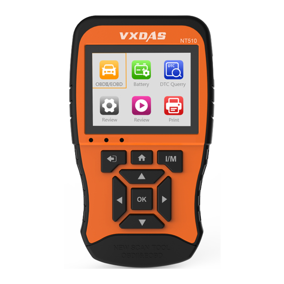
1. OBD II Cable:Connects the Scan Tool to the vehi- cles DLC. 2. LCD Screen: Indicates test results. 3. USB Connector: Connects the Scan Tool to a PC for updating software and printing. 4. ESC Button: Returns to the previous screen. Checks Datastream after selecting specific data items. -
Page 14: Accessories Included
3.3 Accessories Included 1. User's Manual-- Instructions on tool operations. 2. OBDII cable-- Provides power to tool and communi- cation between tool and vehicle. 3. USB cable -- Used to print retrieved data and update software. 4. Protective ABS Case--A ABS case to store the tool when not in use. -
Page 15: System Setup
3.6 System Setup The System Setup functions allow you to adjust default settings and view information about the scan tool. 1.Language: Selects the desired language. 2.Unit of measure: Sets the unit of measure to English or Metric. 3.Beep Set: Turns on/off beep. 4.Key Test: Checks if the keyboard is working properly. -
Page 16: Vehicle Coverage
Unit of Measure Metric is the default measurement unit. 1) From Unit of Measure screen, use the OK button to select the desired unit of measurement. Keyboard Sound The default setting is Beep On. 1) From Beep Set menu, use the OK button to select ON or OFF to turn on/off... -
Page 17: Product Troubleshooting
It is required by EPA that all 1996 and newer vehicles (cars and light trucks) sold in the United States must be OBD II compliant and this includes all Domestic. Asian and European vehicles. A small number of 1994 and 1995 model year gasoline vehicles are OBD II compliant. -
Page 18: Obdii Diagnosis
Problem Possible Cause Likely Solutions Vehicle Linking 1. Vehicle is not OBD 1.Verify that the vehicle is Error OBDII compliant. compliant. 2.Verify that the ignition is 2. Ignition is off. 3. Bad connection. 3.Reset the tool by turning the ignition off,waiting 10 seconds,then turning the ignition back on. -
Page 19: Read Dtc
5) Turn on the scan tool. Select OBDII from the Main Screen. 6) Press the OK button to wait for the Menu to appear. A sequence of messages displaying the OBDII protocols will be observed on the display until the vehicle protocol is detected. -
Page 20: Dtc Query
3.View DTCs and their definitions on screen 4.If more than one DTC is found, use the UP/DOWN scroll button to check all the codes. Read Codes P0010 1/11 A Camshaft Position Actuator Circuit/Open Bank 1 If retrieved DTCs contain any manufacturer specific or enhanced codes, a"The vehicle’s code is defined by the manufacturer, please enter to select the manufactur- er."message comes up prompting you to select vehicle... -
Page 21: Live Data
NOTE: Erasing codes does not mean that trouble codes in ECU have been eliminated completely. As long as there is fault with the vehicle, the trouble codes keeps on presenting. This function is performed with key on engine off (ROEO). Do not start the engine. 1.Use the UP/DOWN scroll buttons to select Clear DTC from Diagnostics Menu and press the OK button. - Page 22 2.View live PIDs on the screen. Use the UP/DOWN or Left/Right scroll button for more PIDs if additional in formation is available on more than one page. Select Items Select Items Fuel system 1 status [√] Fuel system 1 status Fuel system 2 status [√] Fuel system 2 status...
- Page 23 Recording Data Data Stream View All Items Select Items View Graphic Items Record All Record Select A. Record All 1. Use UP/DOWN scroll button to select Record All from Live Data menu and press the OK button. 2. The scan tool will start timing to record retrieved live data.
-
Page 24: Freeze Frame
4.4 Freeze Frame Freeze Frame Data allows the technician to view the vehicle's operating parameters at the moment a DTC is detected. For example, the parameters may include engine speed (RPM), engine coolant temperature(ECT), or vehicle speed sensor (VSS)etc. 1.Select Freeze Frame from Diagnostic Menu and press the OK button. -
Page 25: I/M Readiness
4.5 I/M Readiness I/M Readiness function is used to check the operations of the Emission System on OBD2 compliant vehicles. It is an excellent function to use prior to having a vehicle inspected for compliance to a state emissions program. I/M Readiness Spark Pd DTC... - Page 26 such monitors may be allowed to be "Not Ready" to pass the emissions inspection. -- Indicates that a particular monitor being checked has completed its diagnostic testing. -- Indicates that a particular monitor being checked has not completed its diagnostic testing. -- The monitor is not supported on that vehicle.
-
Page 27: Smog Check
For compression ignition engines: • MIS -- Misfire Monitor • FUEL -- Fuel System Monitor • CCM -- Comprehensive Component Monitor • EGR - EGR System Monitor • HCCAT -- NMHC Catalyst Monitor • NCAT -- NOx Aftertreatment Monitor • BP -- Boost Pressure System Monitor •... -
Page 28: O2 Sensor
4.8 O2 Sensor OBD2 regulations set by SAE require that relevant vehicles monitor and tests on the oxygen (O2) sensors to identify problem related to fuel efficiency and vehicle emissions. These tests are not on-demand tests and they are done automatically when engine operating conditions are within specified limits. -
Page 29: Mode
4.9 Mode 6 Mode 6 (On-Board Monitor Test) is useful after servic- ing or after erasing a vehicle's control module memory. The On-Board Monitor Test for non-CAN-equipped vehicles retrieves and displays test results for emis- sion-related power train components and systems that are not continuously monitored. - Page 30 4.After you select the vehicle manufacturer, the scan tool shows the On-Board Monitors tests for specific monitoring systems. If the vehicle under test does not support the mode,an advisory message will be displayed on the screen. 4.10 Mode 8 Mode 8 (The Component Test) function allows initiating a leak test for the vehicle's EVAP system.
-
Page 31: Viewing Vehicle Information
4.11 Viewing Vehicle Information The Vehicle Info. function enables retrieval of Vehicle Identification No. (VIN), Calibration ID Nos.(CINs), Cali- bration Verification Nos.(CVNs) . Vehicle Information Vehicle Identification Number(VIN): LFV3A24G9D3020130 Calibration Identifications(CID): CID1: JMB*36761500 Calibration Verification Numbers(CVN): CVN1: 4A4D422A CVN2: 33363736 1.Select Vehicle Info. -
Page 32: Core Analysis
4.13 Core Analysis The Core Analysis function allows viewing the perfor- mance of the vehicle. Performance 2749/min Engine RPM Vehicle Speed 26mph Engine Coolant Temperature 419℉ Intake Air Temperature 32℉ Fuel Rail Pressure 0.0psi < 1/17 > 1.Select Core from Diagnostic Menu and press OK button. -
Page 33: Battery Test
4.15 Battery Test The Battery Test function allows viewing the status and the voltage of the vehicle. Battery Battery Volt 11.6V Engine: Normal battery voltage, good battery status. 1.Select Battery from Diagnostic Menu and press OK button. 2.You can clearly see the status and the voltage of the vehicle. -
Page 34: Review And Print Data
3.Press UP/DOWN to change input,press LEFT/RIGHT to select position. Then press OK button to confirm and the scan tool will display this code's definition on screen. If definition could not be found(SAE or Manufacturer Specific), the scan tool displays"The fault code is not found in the database"... -
Page 35: Printing Data
PC or laptop with the USB cable supplied. To print out retrieved data, you need the following tools: NT510 Scan tool A PC or laptop with USB ports A USB cable 1.Download the applications in our website: www.VX-... -
Page 36: Update And Warranty
1) The sole responsibility of Humzor under the Warranty is limited to either the repair or, at the option of VXDAS replacement of the scan tool at no charge with Proof of Purchase. -
Page 37: Service Procedures
Manufacturer's Service Center. 3) VXDAS shall not be liable for any incidental or con- sequential damages arising from the use, misuse, or mounting of the scan tool. Some states do not allow limitations on how long an implied warranty lasts, so the above limitations may not apply to you. - Page 38 Address: Fuquan Building A709, Qingquan Road ,Longhua New District,518131 Shenzhen, China Website: www.vxdas.com Email: info@vxdas.com...
Need help?
Do you have a question about the NT510 and is the answer not in the manual?
Questions and answers