Table of Contents
Advertisement
Advertisement
Table of Contents

Subscribe to Our Youtube Channel
Summary of Contents for Hercus 260
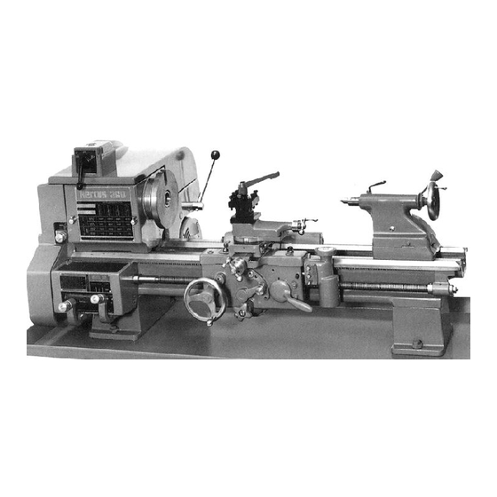
- Page 1 260 LATHE MIAINTENANCE MANUAL...
- Page 2 Cross Feed or Compound Rest Screw — including procedure for Elimination of wear on existing parts Headstock Spindle Page 6 Back Gear Drive Belt from yoke Appendix A Assembly Drawings Appendix B Maintenance Tool Drawings Appendix C List of other material on 260 Lathe...
- Page 3 GOOD OPERATING PROCEDURES Do not rest tools on the bed or slideways Keep the bed and slides clean and free from swarf and moisture Always clean the spindle nose and mating component before mounting Do NOT leave the key in the lathe chuck 5/ When removing chucks from the spindle, engage the back gear to lock the spindle.
- Page 4 LUBRICATION The oiling points are illustrated on the photograph from the "Text Book of Turning" reproduced below. When in regular use, all points should be oiled daily with a few drops and the excess wiped off. Rear Leadscrew Bearing — Half Nuts Tailstock Handwheel Bearing Back Gear*...
- Page 5 CHECKS AND ADJUSTMENTS The following adjustments should be checked periodically to ensure trouble free operations:— Belt Tension The motor and drive belts should be checked regularly for correct tensioning. The belt tension is correctly set when a light finger pressure midway between the pulleys will give a deflection of 10 -13 mm.
- Page 6 REPLACEMENT OF PARTS Cross Feed Nut Wind the cross slide forward until the nut comes off the screw Loosen the locking screw and remove the nut Transfer the locking pin and screw to the new nut Insert the new nut in the cross slide Engage the screw in the nut and wind the cross slide forward as far as possible Back off one turn and tighten the locking screw.
- Page 7 Procedure for removing and replacing Headstock Spindle for replacing any part requiring this operation This is the preferred procedure using the spindle puller details of which are given onDrawings M4 and M5 in Appendix "B". An alternative method is given in the Text Book of Turning. The front and rear bearing caps are removed and the take-up nut unscrewed using the "C"...
- Page 8 APPENDIX "A" Assembly Drawings T Headstock Reverse Bracket Tailstock AM Gearbox A 12, A 18, A 23 AM Apron, Saddle and Compound Rest A 14 CM Apron A 36 T Drive Unit...
- Page 16 APPENDIX "B" Maintenance Tool Drawings Remove Spindle with Puller Replacing Spindle with Puller — Stage 1 Replacing Spindle with Puller — Stage 2 M 4, M 5 Details of Spindle Puller Details of Special Spanners...
- Page 24 Video Programme on Basic Lathe Instruction Video Programme on Lathe Maintenance Video Programme on Lathe Maintenance For further details, contact your local HERCUS Distributor or — For further details, contact your local HERCUS Distributor or — F.W. HERCUS 12 CAMIRA STREET REGENCY PARK, S.
Need help?
Do you have a question about the 260 and is the answer not in the manual?
Questions and answers
I need measurements for: Bed swing length weight for hercus 260 model ATM Serial No 15976 please