Table of Contents
Advertisement
INTEROPERABILITY NOW
Installation and Operation Manual
NXU-2A
Network Extension Unit
JPS Interoperability Solutions
5800 Departure Drive
Raleigh, NC 27616
919-790-1011
Email:
sales@jpsinterop.com
/
support@jpsinterop.com
www.jpsinterop.com
JPS P/N 5041-200200
Revision 2.03
January 2019
Interoperability Now!
Advertisement
Table of Contents

Summary of Contents for JPS NXU-2A
- Page 1 INTEROPERABILITY NOW Installation and Operation Manual NXU-2A Network Extension Unit JPS Interoperability Solutions 5800 Departure Drive Raleigh, NC 27616 919-790-1011 Email: sales@jpsinterop.com support@jpsinterop.com www.jpsinterop.com JPS P/N 5041-200200 Revision 2.03 January 2019 Interoperability Now!
- Page 2 CAUTION Changes or modifications to this equipment not expressly approved by JPS Interoperability Solutions could void the user’s authority to operate this equipment.
-
Page 3: Table Of Contents
Connection to Radio or Other Four-Wire Device (J7) ..............2-8 2.8.4 Network Connection, J3 ........................2-8 2.8.5 Serial Port Connection, J4 ......................2-9 2.8.6 Connecting Equipment and Computers to an NXU-2A ..............2-9 CONFIGURATION ............................3-1 .............................. 3-1 ENERAL ........................3-1 ONFIGURATION ETAILS ...................... - Page 4 ETWORK ANAGEMENT SUPPORT ........................3-11 OMMUNICATIONS 3.5.1 Store Setup Changes with SAVE Command .................. 3-12 3.5.2 NXU-2A Configuration Using the NXU-2A Setup Utility .............. 3-12 ........................ 3-15 ETWORK ONFIGURATION I/O DESCRIPTIONS.......................... 3-15 3.7.1 Audio Input ............................ 3-16 3.7.2 Audio Input Test Point ........................3-16 3.7.3...
- Page 5 NXU-2A Operations Manual List of Figures NXU-2A B ....................1-2 IGURE ASIC LOCK IAGRAM NXU-2A R ....................1-3 IGURE IMPLE ADIO YSTEM 2-1 O .......................... 2-4 IGURE UTLINE IMENSIONS 2-2 C ....................2-5 IGURE ONTROL AND ONNECTOR OCATIONS 2-3 NXU-2A I ........................
- Page 6 NXU-2A Operations Manual Glossary Glossary Carrier Operated Relay A signal from a receiver that gives a positive indication that a carrier or signal is being received and that the receiver is unsquelched. It has the same function as Carrier Operated Squelch (COS).
-
Page 7: General Information
Any NXU-2A can be set up as a server or as a client depending on system needs. The RS-232 interface allows for different baud rates between the server and the client. -
Page 8: Network Details
Mbps and interconnects to an Ethernet hub or switch using standard CAT 5 twisted pair cable, also known as UTP. The maximum cable length between an NXU-2A and its hub port is 100 meters. With the right connective equipment (recommended or supplied by JPS), the NXU- 2A’s Ethernet port can be linked with virtually any LAN, WAN, or the Internet, no matter... -
Page 9: Applications
NXU-2A Operations Manual 1.4 Applications Figure 1-2 below illustrates a basic NXU-2A application in which a communications transceiver is connected via a network to a remote audio console. The transmit/receive audio and PTT/COR signals are transported digitally across the network and appear at the other end. -
Page 10: Specifications
NXU-2A Operations Manual 1.5 Specifications Table 1-1 Specifications RX Audio Input Input impedance Balanced 47k ohms, transformer coupled. Incoming signals adjustable from –30 to +11 dBm to set 0 dBm nominal input; Input Level +15 dBm clipping. +20 dB boost configurable Frequency Response 10 Hz to 3600 Hz +/- 2dB. -
Page 11: Equipment And Accessories Supplied
Generic Radio Interface Cable; unterminated at radio end; 15 ft.t 5961-291115 Interface cables for a very wide range of commercial radios are available for purchase. Email JPS or consult the JPS Interoperability Solutions website for a listing: Email: sales@jpsinterop.com support@jpsinterop.com www.jpsinterop.com... - Page 12 NXU-2A Operations Manual This Page Left Intentionally Blank. Interoperability Now!
-
Page 13: Installation
Contact the carrier and file a shipment damage claim. A full report of the damage should also be reported to the JPS Customer Service Department. The following information should be included in the report: ➢... -
Page 14: Installation Overview
REMARQUE: Utilisez seulement la Class 2 de la generation electrique qui est inclus avec l'equipement. 3. Interconnect the unit with the communications system via the NXU-2A's rear panel connectors. J7 provides the audio and control lines necessary to interface the NXU- 2A to your audio equipment. -
Page 15: Installation Considerations
Careful attention to the following installation suggestions should result in the best unit/system performance. Figure 2-1 provides overall unit dimensions. The NXU-2A must be installed in a structure that provides both protection from the weather and assurance of ambient temperatures between -10 and +55 degrees C. Since the unit is neither splash proof nor corrosion resistant, it must be protected from exposure to salt spray. - Page 16 NXU-2A Operations Manual Figure 2-1 Outline Dimensions Interoperability Now!
- Page 17 NXU-2A Operations Manual Figure 2-2 Control and Connector Locations Interoperability Now!
-
Page 18: Internal Configuration
NXU-2A Operations Manual 2.5.1 Internal Configuration The illustration below shows the NXU-2A with its top cover and rear panel removed. There is normally no reason to remove the top cover, as the NXU-2A has no internal user-serviceable configuration controls. Figure 2-3 NXU-2A Internal View... -
Page 19: Power Requirements
NXU-2A Operations Manual 2.6 Power Requirements The NXU-2A is designed to operate from a nominal +12V DC supply. The unit will meet all of its specifications over a voltage range of +11 to +15 VDC and will be damaged by a DC source that delivers a constant (non-transient) DC voltage above this range. -
Page 20: Audio Level Adjustment Potentiometers And Input Test Point
COR and PTT control signals. You only need this adapter if you are planning to connect an NXU-2A to a radio and you are using a cable specifically designed to connect an ACU-1000 to that radio. The adapter makes the NXU-2A audio connector pinout match the one found on the ACU-1000. -
Page 21: Serial Port Connection, J4
The RS-232 serial cable supplied with the NXU-2A is a straight-through cable used to connect the NXU-2A to a PC serial port. In order to connect the NXU-2A port to an ACU-1000, you need a DB-9 male-male null modem cable, also called a crossover cable. - Page 22 NXU-2A Operations Manual RS232 RS232 Device Straight Device Device Null Device Through Modem LAN, WAN Cable Cable Or T1 COMP NXU-2 NXU-2 ACU-1000 RS232 Device Device Straight Through Cable RS232 Device Null Device Modem Cable RS232 Null Device Device Modem...
-
Page 23: Configuration
0.0.0.0 If the above network parameters are compatible with your network then you may attach the NXU-2A to your network and use your web browser or telnet client to configure the NXU-2A as outlined in Section 3.6 Network Configuration. NOTE: To restore the factory default conditions, remove and reapply power to the unit while rear panel switch “SW1”... -
Page 24: Configuration Using An Rs-232 Terminal Program
Alternatively the NXU-2A may be configured manually using any RS-232 terminal program. Both methods are described. If you want to use the NXU-2A Setup Utility you may skip to Section 3.5.2. 3.3.1 Configuration Using an RS-232 Terminal Program A terminal program is needed to communicate with the NXU-2A for initial configuration. - Page 25 With the serial cable connected and the PC running a terminal program set to the above parameters, apply power to the NXU-2A. Wait at least 10 seconds after power up of the NXU- 2A and type +++ (three plus signs) on your keyboard. You must type all 3 ‘+’ characters within 1 second.
-
Page 26: Command Summary
NXU-2A Operations Manual 3.3.2 Command Summary This is a full list of the commands available in the NXU-2A command mode. More detail is given on the following pages. You can get a one-line summary of each command by typing HELP followed by the command. -
Page 27: Setting Unit Ip Address
VSENSE <0/1/2> - set the VOX/VMR sensitivity to low (0), medium (1), or high (2) 3.3.3 Setting Unit IP Address The first thing you should do is to set the IP address of the unit. The NXU-2A comes from the factory with a default IP address set to 192.168.1.200. Set the address by typing: MYIP <IP address>... -
Page 28: Client/Server Selection
SRVRIP and SRVRPORT commands. For example, if a client unit is going to be connected to a server NXU-2A at address 192.168.1.10 and port 1221, then the commands must be issued: SRVRIP 192.168.1.10... -
Page 29: Vox Hang Time
2000, 3000, or 4000 to select the hang time. The factory default is 500 milliseconds. 3.3.11 COR Inhibit Time In some applications it may be necessary to inhibit the NXU-2A’s response to the COR input (whether hardwired COR or VOX) for a brief period of time (and under certain circumstances) in order to avoid problems with the “ping pong”... -
Page 30: Voice Compression Settings
NXU-2A Operations Manual 3.3.13 Voice Compression Settings In order to send voice information over an IP network efficiently the NXU-2A uses digital signal processing algorithms to compress the voice information so that it requires less network bandwidth. The NXU-2A offers several different voice compression methods to support a variety of applications. -
Page 31: Command Port
NXU-2A Operations Manual 3.3.16 Command Port The port used by the NXU-2A for receiving commands via the telnet protocol or from a WAIS Controller. The value defaults to 23 and under normal circumstances should not need to be changed. If necessary, the command port may be changed by using the CMDPORT command. -
Page 32: Network Management: Snmp Support
By default, the SNMP process (agent) is enabled and running, but may be disabled by changing the “SECURITY” Setting (see section on SECURITY). The Management Information Database [MIB] associated with the NXU-2A may be obtained by contacting customer support at JPS Interoperability Solutions. NOTE: SNMP not functional in current revision on NXU-2A software. Contact... -
Page 33: Communications Mode
Connectionless mode consists solely of a unicast UDP channel for VoIP traffic (along with the status bits such as PTT and COR) between the NXU-2A and another unit. No serial traffic is exchanged. This mode is reserved for special applications such as the JPS WAIS (Wide Area Interoperability System) and should not be used for day-to-day operation. -
Page 34: Store Setup Changes With Save Command
No installation is required. With the NXU-2A connected via the serial cable to a suitable serial port on the PC, apply power to the NXU-2A. You should see the lights on the front panel blink in succession. Then run the NXU-2A Setup Utility by double- clicking on the program or by using the Run command from the Windows Start menu. - Page 35 Make the appropriate changes by selecting the various menu options. When you have finished making configuration changes, click the Update Settings button to save the new configuration information in the NXU-2A. The NXU-2A will restart and the new settings will then be in effect.
- Page 36 To add the current unit to the configuration history, type a name for the unit into the box beside the Add Current button and click the button. The NXU-2A will be added to the list of units shown in the NXU-2A List window. To review the settings for a particular unit, simply choose it from the list and the settings will be displayed.
-
Page 37: Network Configuration
LOGOUT may be typed to disconnect the telnet connection manually. A web browser may also be used to browse the IP address of the NXU-2A. From the opening page select NXU-2A Configuration. The following page will be seen where configuration changes can be made and saved. -
Page 38: Audio Input
2.5V DC nominal, and the input is protected from momentary surges up to +100 V DC. 3.7.6 PTT Output The PTT output from the NXU-2A is an open drain type. It can sink up to 100 mA of current, and can withstand open-circuit voltages up to +60V DC. In order to avoid conflicts with internal pull-up resistors on the PTT lines of some radio equipment, there is no internal pull-up resistor on the NXU-2A PTT output. -
Page 39: Operation
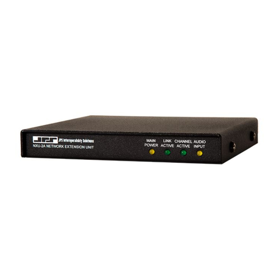
The green Link Active LED is illuminated whenever the NXU-2A has an IP connection open to another NXU-2A on the network. If this indicator is not lit, either the NXU-2A does not have an active VoIP connection or the connection has been lost. -
Page 40: Operation At Power-Up
If a unit has an active COR input, that unit’s audio input will be transferred across the network and will appear at the audio output on J7 at the other unit. While the COR input of an NXU-2A is active, the PTT output will remain active on another NXU-2A it’s connected to. The audio channels are independent, and full duplex operation is possible. -
Page 41: Auxiliary I/O
Command Mode. 4.4.5 Auxiliary I/O The NXU-2A has two sets of independent inputs and outputs that may be used for control of the user’s equipment. AUX IN 0 and AUX IN 1 are active-low inputs which, when activated on one end, will cause AUX OUT 0 and AUX OUT 1 on the other end to become active. -
Page 42: Web Browser Control
NXU-2A Operations Manual 4.5.2 Web Browser Control The NXU-2A client connection may be managed by browsing to the NXU-2A client IP address and selecting the Connection Management menu option. The user may then issue connect or disconnect commands via the web browser. -
Page 43: Security
NXU-2A. 4.6.1 Password Setting The NXU-2A security level may be set to require a password for HTTP access. The password may be programmed while in the command mode using the PASS command followed by the desired password. -
Page 44: Web Access With Password Protection
NXU-2A Operations Manual 4.6.2 Web Access with Password Protection When the NXU-2A security level is set to require a password, any attempt to access the unit via HTTP will result in the web browser displaying the following dialog: Figure 4-2 Network Password Dialog In order to access the NXU-2A you must enter the password that was previously programmed using the PASS command. -
Page 45: Nxu-2A Troubleshooting
5 NXU-2A Troubleshooting The following table may be used to troubleshoot any problems you may encounter during installation or operation of the NXU-2A. Table 5-1 Troubleshooting Symptom: Possible Causes: Main Power LED is not illuminated Check that AC adapter is operational and firmly plugged in. - Page 46 Verify that the COR polarity is programmed continuously. properly. See section 3.3.8. If NXU-2A is attached to a radio COR line, make sure the radio squelch is set properly. Audio has pauses and/or gaps in it. Check for low bandwidth or excessive latency...
-
Page 47: Nxu-2A Faq (Frequently Asked Questions)
COR is usually obtained from a radio and indicates that a signal is being received. If you do not have a COR line, or a line that performs this function, then you can either tie the NXU-2A COR line to its active state or you can use VOX mode. VOX mode is preferred since enabling COR permanently will cause data to flow continuously across the link, even if no audio is present. - Page 48 255.255.255.0 and the gateway IP address to 0.0.0.0. After losing power on one end of an NXU-2A link, it takes a while for the units to re- establish communications. Why is this? The NXU-2A will wait up to 20 seconds before determining that the link has been disconnected.
- Page 49 Should I use a firewall with the NXU-2A? Strictly speaking from the standpoint of the NXU-2A, there is no reason to use a firewall with the NXU-2A. The NXU-2A is a stand-along network device which poses minimal security risks.
- Page 50 Should I use NAT with the NXU-2A? The only time it is advisable to use NAT with the NXU-2A is when you wish to have multiple units on a network, but have only one public IP address. An example of this would be a bank of NXU-2As sharing a broadband type connection such as DSL or cable modem where only one IP address is allocated by your ISP.
- Page 51 24, 32, and 64 Kbps vocoders. In general data should be sent via the RS-232 port. I've connected my radio to the NXU-2A, I have the levels turned all the way up, and can still barely hear the audio. What's wrong? The NXU-2A uses balanced audio on the input.
- Page 52 NXU-2A and allows convenient menu driven setup on Windows computers. I've configured my terminal program (or the NXU-2A Setup Utility) and followed the procedure exactly, and I still can't get the 'OK' prompt telling me that the NXU-2A is in Command Mode. Now what?
-
Page 53: Theory Of Operation
This operation is outlined below. When power is applied to an NXU-2A it either waits for a connection (if it’s a server) or attempts a connection to a server (if it’s a client). It will attempt to connect to the server that has an IP address identical to the SRVRIP address programmed in the client. - Page 54 NXU-2A Operations Manual This Page Left Intentionally Blank. Interoperability Now.
-
Page 55: Index
Configuration ............3-1 Network Configuration ........3-15 Connection Management Screen ......4-4 Network Details ............ 1-2 Connectors ............2-7 NXU-2A Setup Utility ........3-12 Control and Connector Locations ......2-5 Controlling Connections ........4-3 COR ..............1-6 Operation .............. 4-1 COR Inhibit Time .......... - Page 56 NXU-2A Operations Manual Serial Port Configuration........3-1 Serial Port Settings ..........3-7 UDP ..............1-6 Setting Unit IP Address ........3-5 Unpacking and Inspection ........2-1 Setup Utility ............3-2 Specifications ............1-4 VMR ..............3-9 Voice Compression Settings ......... 3-8 TCP ..............
Need help?
Do you have a question about the NXU-2A and is the answer not in the manual?
Questions and answers