
Summary of Contents for YANGZHOU SUPER MACHINE TOOL CD6240
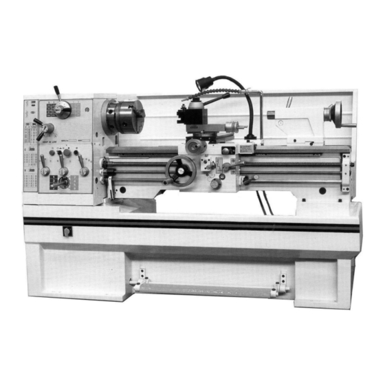
- Page 1 Instructions Manual for CL-38 (L190) 04/03/2020 INSTRUCTION MANUAL AND PARTS LIST LATHE MODEL: CD6240 MADE IN: YANGZHOU SUPER MACHINE TOOL CO.,LTD. ADDRESS: No.198 HEYE WEST ROAD,YANGZHOU,CHINA...
-
Page 2: Table Of Contents
Instructions Manual for CL-38 (L190) 04/03/2020 CONTENTS …………………………………………… 1. Guideline for Safety Operation 1-1 Safety Points for Attention ………………………………………………… 1-2 Danger of Operation ……………………………………………………… 1-3 General Safe Rules for Operator of the Lathe…………………………… 1-4 Protection of the Chuck …………………………………………………… 1-5 The Use of Emery Cloth in Metal Processing Can Cause Danger … …….. 1-6 Safety devices………………………………………………………………... - Page 3 Instructions Manual for CL-38 (L190) 04/03/2020 ………………………………………………………………………… 21. Saddle …………………………………………………………………… 22. Lubrication ………………………………………………………… 23. Tailstock Assembly ……………………………………………………… 24. Chuck Guard Cover …………………………………………………………………… 25. Follow Rest …………………………………………………………………… 26. Steady Rest ………………………………………………………… 27. Lead Screw Guard ……………………………………………………………… 28. Chip Protection...
-
Page 4: Guideline For Safety Operation
Instructions Manual for CL-38 (L190) 04/03/2020 .1. Guideline for Safety Operation The lathe is a high speed and powerful machine and can cause danger if operate it improperly. Before operating the lathe please read the following guidelines of safety operation. Take care and observe to make the lathe be under normal operation environment so as to avoid danger. -
Page 5: Danger Of Operation
Instructions Manual for CL-38 (L190) 04/03/2020 5. Before starting the lathe, you should understand how to stop it. 6. The lathe cannot be operated under overload. 7. Stop running of the lathe immediately in case any accident occurs. 8. When mounting the chuck or other attachment on the spindle, switch off power supply of the lathe to prevent rotation of the spindle. - Page 6 Instructions Manual for CL-38 (L190) 04/03/2020 fluid continuously especially the original fluid, it can cause the skin allergic or ill if seriously, even the emulsion can also cause the same. Therefore following precautions should be taken: a. Avoid any unnecessary contact. b.
-
Page 7: General Safe Rules For Operator Of The Lathe
Instructions Manual for CL-38 (L190) 04/03/2020 b. The weight and type of the claws are off standard. c. The working radius of the claw is unsuitable. d. The claw ahs bad lubrication. e. It is unbalanced. f. The dynamic factor is not considered in the jigging force. g. - Page 8 Instructions Manual for CL-38 (L190) 04/03/2020 4. Grasp the handy tool or the operation grippe on recommended positions. 5. Do not allow to leave other handy tool or operation gripper on the chuck. 6. Do not allow to use broken, damaged or defected tool. 7.
- Page 9 Instructions Manual for CL-38 (L190) 04/03/2020 by the chuck or the workpiece. 20. Take care not to push the handle, to operate the clutch or to witch on power supply to cause accident. 21. Master every function and all kinds of operation methods. 22.
- Page 10 Instructions Manual for CL-38 (L190) 04/03/2020 The file or the deburring tool could bump the chuck. 34. For the lathe driven by the clutch, take care that the clutch should be at the position the lathe is stopped when making measurement. 35.
-
Page 11: Protection Of The Chuck
Instructions Manual for CL-38 (L190) 04/03/2020 43. Never mount the workpiece too large or heavy toward the lathe. 44. Never mount the workpiece too large or heavy toward the operator. 45. Use necessary tools to treat the workpiece. 46. Never apply excessive force on the attachment or the operation lever. -
Page 12: The Use Of Emery Cloth In Metal Processing Can Cause Danger
Instructions Manual for CL-38 (L190) 04/03/2020 it is indeed required by customer, the special chuck guard can be provided but it should be confirmed that only the face chuck is used and any case should be responsible by customer himself. 1-5 The Use of Emery Cloth in Metal Processing Can Cause Danger In all accidents occurred on the lathe, most are from the use of emery cloth to cause breakage of fingers, or even to amputate occasionally. - Page 13 Instructions Manual for CL-38 (L190) 04/03/2020 emery cloth, then the emery cloth should be used in following cases: a. Nail the emery cloth on a quality wood board to grind; b. The emery cloth is fixed on and jigged by the tool holder to grind. c.
-
Page 14: Safety Devices
Instructions Manual for CL-38 (L190) 04/03/2020 When the end of the workpiece is polished, only a short piece of the emery cloth shall be used as it cannot be wound. When polish by the emery cloth is made, never operate by wearing gloves. - Page 15 Instructions Manual for CL-38 (L190) 04/03/2020 spring prevents the pulling-in of clothes into the guide spindle, • chip protection, · securing screw • an overload clutch on the feed shaft, • safety screws for the Camlock bolts on the workpiece holder. a.
- Page 16 Instructions Manual for CL-38 (L190) 04/03/2020 c. Protective cover on the headstock The headstock of the lathe is provided with a protective cover and a position switch. The lathe only starts when the protective cover is mounted. positions switch WARNING! Only remove the protective cover when the main switch of the lathe is turned off and secured by a padlock.
- Page 17 Instructions Manual for CL-38 (L190) 04/03/2020 e. Chip protection The lathe is provided with a protective cover for the tool cutting chip. Chip protection closed Chip protection opened Integrated position switch f. securing screw Tighten the securing screw at the end of the lathe bed in order to prevent the tailstock from unintentional drawing-out of the lathe bed.
-
Page 18: Level Of Noise
Instructions Manual for CL-38 (L190) 04/03/2020 Safety check Check the lathe at least once per shift. Inform the person responsible immediately of any damage, defect or change in the operating function. Check all safety devices • at the beginning of each shift (with the machine stopped), •... -
Page 19: Specification
Instructions Manual for CL-38 (L190) 04/03/2020 3. Specification Capacity Swing Over Bed 360mm(14") or 410mm(16") Swing Over Cross Slide 215mm(81/2") or 255mm(10") Swing In Gap Diameter×Width 540(211/4") or 580(23")×190(71/2") Height of Center 185mm(71/2") or 205mm(8") Distance Between Centers 1000mm(40")/1500 mm Width of Bed 250mm(10") Cutting Tool Max Section... -
Page 20: Lifting
Instructions Manual for CL-38 (L190) 04/03/2020 4. Lifting Use a sling-chain to sling the lathe as in fig position the saddle and tailstock along the bed to obtain balance. Important: The sling-chain should not touch the leadscrew or Feed-shaft to avoid damage. Unloading of the machine. -
Page 21: Cleaning
Instructions Manual for CL-38 (L190) 04/03/2020 5. Cleaning Before operating any controls remove the anticorrosion coating from all slideways and the end gear train, using white spirit or kerosene. Do not use cellulose solvents for cleaning, as they will damage the paint finish. -
Page 22: Lathe Alignment Part
Instructions Manual for CL-38 (L190) 04/03/2020 /1680 3 80 1 1 80 1 30 Fig.2 Construction of the Ground Due to the recent tendency of utilizing Ultra-Hard Alloy Steel tools, it surely increases the speed of heavy cutting comparing to the previous steel tool. But, in the mean time, it easily happens to the vibration of the machine. -
Page 23: Lathe Alignment Part.2
Instructions Manual for CL-38 (L190) 04/03/2020 not supported at the free end. Micrometer reading at each end of the turned length (at A and B of Fig.4) should be the same. To correct a difference in readings, slacken and release the four-headstock hold-down screws (J) shown in Fig.4 and adjust the set-over screw (K) beneath the headstock. -
Page 24: Slide Ways Attention
Instructions Manual for CL-38 (L190) 04/03/2020 9. Slide Ways Attention Tapered gib strips are fitted to slideways of saddle cross-slide and top (compound) slides so that any slackness, which may develop can be rectified. Ensure that slideways are thoroughly cleaned and lubricated before attempting adjustment. -
Page 25: Electrical Controls
Instructions Manual for CL-38 (L190) 04/03/2020 11. Electrical Controls The power switches are fitted on the face of electrical box in back of the bed and below the headstock. Except the main switch, all electrical controls are fitted in the front of the headstock. 1.Move the power switch set at ON position then the indicator lamp glows. -
Page 26: Speed Controls
Instructions Manual for CL-38 (L190) 04/03/2020 12. Speed Controls (2 Speed Motor) Spindle speeds: Selected by the two lever controls and electrical switch, on the headstock and stand. The sixteen available speeds are shown directly on the data plate. While the electrical switch set at (1) position, the small lever rotated right-hand side, it provides speeds from 1800-510r.p.m., and rotated to left-hand side, it provides speeds from 330-90r.p.m. -
Page 27: Threading Dial Indicator
Instructions Manual for CL-38 (L190) 04/03/2020 13. Threading Dial Indicator A. Whitworth threads Located on right-hand side of the apron on lathes having an Imperial leadscrew. Engage the indicator pinion with the leadscrew and tighten the hand nut to retain indicator in engagement. To cut threads of an even number per inch, close the leadscrew nut as ANY line on the dial passes the datum mark. -
Page 28: Chucks And Chucks Mounting
Instructions Manual for CL-38 (L190) 04/03/2020 B. Metric threads Same as above when a Metric Screw is installed. To provide for the various pitches of metric threads, several gears having different numbers of teeth are mounted on the lower end of the shaft. - Page 29 Instructions Manual for CL-38 (L190) 04/03/2020 faceplate and re-adjust the stud as indicated in the illustration. Fit and tighten the locking screw (B) at each stud before remounting the chuck for work. A reference mark should be made on each correctly fitted chuck or faceplate to coincide with the reference mark scribed in the spindle nose.
-
Page 30: Electric Circuit Control
Instructions Manual for CL-38 (L190) 04/03/2020 15. Electric Circuit Control 15.1 Wiring Diagram... -
Page 31: Electric Board Diagram
Instructions Manual for CL-38 (L190) 04/03/2020 15.2 Electric Board Diagram... -
Page 32: Electric Listing Component
Instructions Manual for CL-38 (L190) 04/03/2020 15.3 Electric Listing Component Type Name Specification High/Low/Stop Switch LW8PS-25/M10T Main Switch LW8GS-25/30000-A Breaker GV2 2.5-4A Breaker DZ451-63 2P C1 Breaker DZ451-63 1P C5 Breaker DZ451-63 1P C2 Thermal overload relay 3UA5940 6.3-10A Thermal overload relay 3UA5940 0.4-0.63A KM1,2 AC Contactor... -
Page 33: Bed Assembly
Instructions Manual for CL-38 (L190) 04/03/2020 16 Bed assembly... - Page 34 Instructions Manual for CL-38 (L190) 04/03/2020...
- Page 35 Instructions Manual for CL-38 (L190) 04/03/2020 Part No. Name Specification CD6236-01-27 Gap Block GB70-85 Socket Head Cap Screw M10×45 GB881-86 Taper Pin 8×85 GB6170-86 GB70-85 Socket Head Cap Screw M8×50 GB118-86 8×40 CD6236-01-26 Guard Assay GB70-85 Socket Head Cap Screw M6×12 GB41-76 CD6236-01-44...
- Page 36 Instructions Manual for CL-38 (L190) 04/03/2020 Part No. Name Specification CD6236-01-41 CL6132-06-11 Plug GB117-86 Taper Pin 5×45 GB894.2-86 External circlip CD6236-01-36 Feed Rod CD6236-01-38 Sleeve GB301-84 Thrust Bearing 8103 CD6236-01-40 Sleeve GB77-85 Set Screw M12×8 GB2089-80 Spring 1×9×20 GB308-84 Steel Ball CD6236-01-55 Sleeve CD6236-01-29...
- Page 37 Instructions Manual for CL-38 (L190) 04/03/2020 Part No. Name Specification RUN6141-106047 Belt Brake Y132M-8/4 Motor GB30-76 Bolt M10×40 GB93-86 Washer GB41-76 RUN6141-106079 Washer RUN6141-106046 Screw GB70-85 Socket Head Cap Screw M8×30 GB6170-86 RUN6246-106051 Screen RUN6246-106090A Coolant Pump Seat GB96-85 Washer RUN6246-106029 Bolt GB6173-86...
-
Page 38: Change Gear
Instructions Manual for CL-38 (L190) 04/03/2020 17 . Change gear... - Page 39 Instructions Manual for CL-38 (L190) 04/03/2020 Part No. Name Specification CL6132-04-77 CD6236-04-72 Cover(360) CD6240-04-72 Cover(410) GB900-88 Bolt M10×85 GB70-85 Socket Head Cap Screw M8×16 CD6240-05-02 Washer CD6240-04-53G1 Change Gear Metric(33T) CD6236-04-53 Change Gear(360) Inch(24T) CD6240-04-53 Change Gear(410) Inch(24T) GB893.1-86 Circlip...
-
Page 40: Headstock Assembly
Instructions Manual for CL-38 (L190) 04/03/2020 18.Headstock Assembly... - Page 41 Instructions Manual for CL-38 (L190) 04/03/2020...
- Page 42 Instructions Manual for CL-38 (L190) 04/03/2020...
- Page 43 Instructions Manual for CL-38 (L190) 04/03/2020...
- Page 44 Instructions Manual for CL-38 (L190) 04/03/2020...
- Page 45 Instructions Manual for CL-38 (L190) 04/03/2020...
- Page 46 Instructions Manual for CL-38 (L190) 04/03/2020...
- Page 47 Instructions Manual for CL-38 (L190) 04/03/2020 Part No. Name Specification GB70-85 Socket Head Cap Screw M6×30 CL6132-04-06 Plug-Oil Inlet CD6236-04-19 Cover Dress CD6236/6240-04-15 Headstock Cover(360/410) CD6236/6240-04-14 Packing(360/410) GB879-85 Spring Pin 5×30 GB70-85 Socket Head Cap Screw M5×16 CD6236-04-74 Bracket CL6132-04-03 Plug GB3452.1-82 O-Ring...
- Page 48 Instructions Manual for CL-38 (L190) 04/03/2020 Part No. Name Specification GB1096-79 8×40 GB1096-79 8×50 CD6236-04-01 Shaft GB278-89 Ball Bearing 80206 CD6236-04-03 Gear Mn=2.5 Z=38 CD6236-04-04 Gear Mn=2.5 Z=33 CD6236-04-05 Sleeve CD6236-04-06 Gear Mn=2.5 Z=23 CD6236-04-07 Gear Mn=2.5 Z=33 GB278-89 Ball Bearing 80205 GB894.1-86 External Circlip...
- Page 49 Instructions Manual for CL-38 (L190) 04/03/2020 Part No. Name Specification CD6236-04-60 Cycle Oil Ring GB276-89 Ball Bearing E213 CD6236-04-57 Sleeve CD6236-04-56 Gear Mn=2 Z=48 CD6236-04-34 Fix Black CD6236-04-33 Set Nut GB297-84 Taper Roller D2007114E GB894.1-86 External Circlip CD6236-04-35 Gear Mn=2.5 Z=43 CD6236-04-36 Gear Mn=2.5 Z=82...
- Page 50 Instructions Manual for CL-38 (L190) 04/03/2020 Part No. Name Specification GB70-85 Socket Head Cap Screw M6×12 CD6236-04-54 Spacer CD6240-04-53 Change Gear(410) Inch(24T) GB70-85 Socket Head Cap Screw M6×14 CD6236-04-52 Cover CD6236-04-52 Packing HG4-692-67 Oil Seal SD25×40×10 GB278-89 Ball Bearing 80105 GB1096-79 6×14...
- Page 51 Instructions Manual for CL-38 (L190) 04/03/2020 Part No. Name Specification CL6132-04-98 Lever Bracket GB1235-76 O-Ring 28×3.1 CL6132-04-94 CD6236-04-76 Bracket...
-
Page 52: Gear Box Control
Instructions Manual for CL-38 (L190) 04/03/2020 19.Gear Box Control... - Page 53 Instructions Manual for CL-38 (L190) 04/03/2020...
- Page 54 Instructions Manual for CL-38 (L190) 04/03/2020...
- Page 55 Instructions Manual for CL-38 (L190) 04/03/2020 Part No. Name Specification GB70-85 Socket Head Cap Screw M6×16 CD6236-05-91 Cover CD6236-05-65 Packing CD6236-05-42 Gear Box Casting GB70-85 Socket Head Cap Screw M8×60 GB118-86 Taper Pin A8×90 CD6236-05-58 Top Plate GB70-85 Socket Head Cap Screw M5×20 CD6236-05-96 Fork...
- Page 56 Instructions Manual for CL-38 (L190) 04/03/2020 Part No. Name Specification HG4-692-67 Oil Seal PD20×35×10 GB70-85 Socket Head Cap Screw M6×16 CD6236-05-11 Bracket CD6236-05-64 Packing GB290-64 Roller Bearing 943/20 CD6236-05-12 Washer GB894.1-86 Circlip CD6236-05-13 Gear Mn=2.25Z=39Mn=1.75 Z=20 CD6236-05-14 Shaft GB1096-79 5×8 GB276-84 Ball Bearing 7000104...
- Page 57 Instructions Manual for CL-38 (L190) 04/03/2020 Part No. Name Specification GB879-86 Spring Pin 4×25 CD6236-05-100 Washer GB70-85 Socket Head Cap Screw M5×12 GB276-84 Ball Bearing 7000104 CD6236-05-67 Shaft CD6236-05-66 Washer CD6236-05-68 Gear Mn=1.75Z=30 Mn=2.25 Z=19 CD6236-05-69 Washer GB894.1-86 Circlip GB276-84 Ball Bearing 7000104 CD6236-05-16...
- Page 58 Instructions Manual for CL-38 (L190) 04/03/2020 Part No. Name Specification CD6236-05-73 Gear Mn=2 Z=22 CD6236-05-74 Gear Mn=1.5 Z=33 CD6236-05-75 Gear Mn=1.75 Z=22 CD6236-05-27 Washer CD6236-05-80 Gear Mn=1.25Z=36 Mn=1.25 Z=20 GB276-86 Roller Bearing CD6236-05-99 Packing CD6236-05-82 Bracket GB70-85 Socket Head Cap Screw M6×16 CD6236-05-35 Lever...
-
Page 59: Apron
Instructions Manual for CL-38 (L190) 04/03/2020 20.Apron... - Page 60 Instructions Manual for CL-38 (L190) 04/03/2020...
- Page 61 Instructions Manual for CL-38 (L190) 04/03/2020...
- Page 62 Instructions Manual for CL-38 (L190) 04/03/2020...
- Page 63 Instructions Manual for CL-38 (L190) 04/03/2020 Part No. Name Specification GB818-85 Screw M4×10 CD6236-06-03 Name Plate GB70-85 Socket Head Cap Screw M8×60 CD6236-06-01 Apron Casting GB117-86 B8×60 CD6236-06-31 Lever CD6236-06-51 Bolt CD6236-06-39 Stopper GB70-85 Socket Head Cap Screw M5×16 GB5782-86 Bolt M6×12 CD6236-06-38...
- Page 64 Instructions Manual for CL-38 (L190) 04/03/2020 Part No. Name Specification GB879-86 Spring Pin 5×42 CD6236-06-26 Lever Head CD6236-06-27 Handle GB308-84 Steel Ball φ6.5 GB896-86 Clip GB77-85 Socket Head Cap Screw M8×6 CD6236-06-43 Cover CD6236-06-42 Packing CD6236-06-41 Fork GB3452.1-82 O-Ring 25.8×3.55 CD6236-06-22 Sleeve GB3452.1-82...
- Page 65 Instructions Manual for CL-38 (L190) 04/03/2020 Part No. Name Specification GB78-85 Screw M6×10 CD6236-06-23 Plug GB1099-79 Wood ruff Key 5×6.5×16 GB70-85 Socket Head Cap Screw M5×25 CD6236-06-08 Dial CD6236-06-07 Hand Wheel CD6236-08-16 Screw Plug GB79-85 Set Screw M5×25 CD6236-06-02 Shaft CD6236-06-04 Sleeve GB2089-80...
-
Page 66: Saddle
Instructions Manual for CL-38 (L190) 04/03/2020 21.Saddle... - Page 67 Instructions Manual for CL-38 (L190) 04/03/2020...
- Page 68 Clamp Handle CD6236-07-19 Clamping Handle CD6236-07-20 Washer CD6236-07-18A Tool Post Shaft(S-Post) CD6236-07-18 Tool Post Shaft(T-Post) GB1155-79 Ball Cup CD6236-07-25A Compound Rest(360S-Post) CD6240-07-25A Compound Rest(410S-Post) CD6236-07-25 Compound Rest(360T-Post) CD6240-07-25 Compound Rest(410T-Post) CD6236-07-17G Nut(Metric) CD6236-07-17 Nut(Inch) CD6236-07-07G Feed Screw(Metric) CD6236-07-07 Feed Screw(Inch)
- Page 69 T-Bracket GB1155-79 Ball Cup GB70-85 Screw M6×25 GB77-85 Screw M6×20 GB77-85 Screw M8×16 CD6236-07-23 CD6236-07-55G Feed Screw(Metric) CD6236-07-55 Feed Screw(Inch) CD6240-07-63a-2 4×18 RUN6246-103004 Bracket CD6236-07-51Ga Nut(Metric) CD6236-07-51a Nut(Inch) GB301-84 Thrust Bearing 8100 CD6236-07-22 Bracket CD6236-07-14 Spacer CD6236-07-30 Bearing Cover CD6236-07-09...
- Page 70 Instructions Manual for CL-38 (L190) 04/03/2020 Part No. Name Specification GB77-85 Screw M8×20 CD6240-07-63a Gear Shaft Mn=1.5 Z=16 CD6236-07-40 Screw CD6236-07-39 Handle Spacer CD6236-07-15 Plug CD6236-07-34 Wiper Cover CD6236-07-33 Wiper CD6236-07-04 Clamp Screw GB70-85 Screw M6×20 CD6236-07-32 Wiper Cover GB818-85 Screw M5×16...
-
Page 71: Lubrication
Instructions Manual for CL-38 (L190) 04/03/2020 22.Lubrication... - Page 72 Instructions Manual for CL-38 (L190) 04/03/2020 Part No. Name Specification CD6236-07-01 13/13 Proper Screw GB97.1-85 Washer CD6236-07-01 10/13 Distributor GB77-85 Screw M4×5 15326C Tie-in Lubrication Tube φ5 2143SC Tie-in φ5/Z1/8 CD6236-07-01 6/13a Pump GB308-77 Ball GB2089-80 Spring 0.5×4×15 GB3452.1-82 O-Ring 11.2×1.8 CD6236-07-01 5/13 Plug...
-
Page 73: Tailstock Assembly
Instructions Manual for CL-38 (L190) 04/03/2020 23.Tailstock Assembly... - Page 74 Instructions Manual for CL-38 (L190) 04/03/2020 Part No. Name Specification GB78-85 5×25 CD6236-08-16 Screw Plug CD6236-08-17 Hand Wheel GB2089-80 Spring 0.6×5×16 GB308-84 Steel Ball Φ6.5 GB894.1-86 Retaining Ring GB301-84 Thrust Bearing 8104 CD6236-08-13 Bracket GB1096-79 5×16 CD6236-08-18 Bolt CD6236-08-19 Handle CD6236-08-14 Dial CD6236-08-15...
- Page 75 Instructions Manual for CL-38 (L190) 04/03/2020 Part No. Name Specification CD6236-08-02 Bedway Wiper CD6236-08-28 Bedway Wiper Plate GB879-86 Spring Pin 5×15 CD6236-08-21 socket wrench GB879-86 Spring Pin 4×25 CD6236-08-22 Clamping Lever GB77-85 Socket Head Set Screw M6×15 CD6236-08-23 Clamping Shaft CD6236-08-24 Clamping Lever GB79-85...
-
Page 76: Chuck Guard Cover
Instructions Manual for CL-38 (L190) 04/03/2020 24.Chuck Guard Cover... - Page 77 Instructions Manual for CL-38 (L190) 04/03/2020 Part No. Name Specification GB70-85 Screw M6×12 GB93-86 Washer CD6236-04F-02 Support Bracket CM6233-F1005 Sleeve GB75-85 Screw M8X20 CD6236-04FA-01 Cover HY8315.4 A=114 handle GB78-85 Screw M6×10 RIN6236-101101 Cover Bracket CD6236-04FA-04 Shaft GB78-85 Screw M8×10 GB70-85 Screw M6×10...
-
Page 78: Follow Rest
Instructions Manual for CL-38 (L190) 04/03/2020 25.Follow Rest... - Page 79 Instructions Manual for CL-38 (L190) 04/03/2020 Part No. Name Specification RUN6246-110019 Rotate Handle GB78-85 Screw M6×8 RUN6246-110004 Bush CD6236-10-11 Screw Shaft CD6236-10-10 Sleeve GB77-85 Screw M6×6 CD6236-10-09 Follow Rest GB879-86 Spring Pin 5×26 RUN6246-110018 Limited Screw CD6236-10-08 Support Shaft GB119-86 6×16 GB278-88 Bearing...
-
Page 80: Steady Rest
Instructions Manual for CL-38 (L190) 04/03/2020 26.Steady Rest... - Page 81 Instructions Manual for CL-38 (L190) 04/03/2020 Part No. Name Specification RUN6246-110019 Rotate Handle GB78-85 Screw M6×8 RUN6246-110004 Bush CD6240-10-05 Screw Shaft CD6236-10-04 Sleeve GB77-85 Screw M6×6 RUN6246-110014 Handle CD6236-10-02 Upside of Steady Rest RUN6246-110013 Clamping Screw GB119-86 10×50 GB879-86 Spring Pin 5×32...
-
Page 82: Lead Screw Guard
Instructions Manual for CL-38 (L190) 04/03/2020 27. Lead Screw Guard Part No. Name Specification Connect Sleeve CD6236-01F-05 CD6236-01F-01 Protect Sleeve 1000 GB70-85 Socket Cap Screw M5×12 CD6236-01F-02 Protect Sleeve 2000 GB70-85 Socket Cap Screw M4×12 Connect Sleeve CD6236-01F-03 1000、1500 Connect Sleeve CD6236-01F-04 2000... -
Page 83: Chip Protection
Instructions Manual for CL-38 (L190) 04/03/2020 28. Chip Protection... - Page 84 Instructions Manual for CL-38 (L190) 04/03/2020 Part No. Name Specification CD6240-20-02 Chip Cover CD6240-20-09 Clamp GB70-85 Screw M4×10 GB97.1-85 Washer CD6240-20-07 Chip Cover CD6240-20-03 Chip Cover Plate CD6240-20-06 Chip Cover Fixing Plate GB80-85 Screw M6×6 CD6240-20-05 Shaft CD6240-20-03 Top Cover Plate...
Need help?
Do you have a question about the CD6240 and is the answer not in the manual?
Questions and answers