
Related Manuals for MEK MTV1000

Summary of Contents for MEK MTV1000
- Page 1 User’s Manual MTV1000 Ventilator System User’s Manual can be modified without announcement for performance improvement. Screens and pictures on User’s Manual may be different from actual product. Eng. Ver. 2.3 2016-08-17...
-
Page 2: Table Of Contents
4.4. Bacteria Filter ..........................30 4.5. Movement Method ........................30 4.6. Installation Guide according to Circuit Type ..............31 Getting Started with MTV1000 ....................33 5.1. General Operation Sequence ....................33 5.2. Quick Ventilation Operation Sequence (Dual Ventilation Mode) ......35 5.2.1. - Page 3 7.4. Accessories ..........................82 7.5. Alarm Operation according to ventilation mode ............85 7.6. SpO / EtCO Monitoring ......................86 7.6.1. / EtCO Connection Information ................86 7.6.2. Monitoring ....................... 86 7.6.3. EtCO Monitoring ......................87 MTV1000 Ventilator System User’s Manual...
- Page 4 Guidance and manufacturer’s declaration – ..............89 electromagnetic immunity ......................89 7.7.3. Guidance and manufacturer’s declaration – ..............90 electromagnetic immunity ......................90 7.7.4. Recommended separation distances ................92 7.8. Product Warranty Policy ......................93 MTV1000 Ventilator System User’s Manual...
-
Page 5: About User's Manual
This user’s manual is provided to users with MTV1000 Ventilator product. Since this user’s manual is compatible with MTV1000 Ventilator, it may not be used with other products manufactured by our company. In case of loss or damage in user’s Manual, you may refer to MEK-ICS web site for downloading the manual file. - Page 6 ▣ If deemed necessary, the company may make any improvement to the product to enhance its performance, without prior notification, MEKICS has no obligation to apply the same specification change to the products already sold. MTV1000 Ventilator System User’s Manual...
-
Page 7: Precautions
If you disassemble the product yourself, you will not receive any service for the product. Turn off the product when you do not use it for a while. MTV1000 Ventilator System User’s Manual... -
Page 8: Cautions When Using The Product
2. Take care not to cause pain on patients from tightening sensors. Also, take care not to tangle patients with sensor cables. 3. If measurement values displayed on the screen are considered inaccurate, measure another patient for comparison. 4. Do not use one product on two patients simultaneously. MTV1000 Ventilator System User’s Manual... -
Page 9: Cautions On Electrical Safety
Only use auxiliary equipment provided by the MEKICS Head Office or MEKICS’ designated representatives. ATTENTION 1. This product uses 10.8V, 4400mAh (2ea), Li-ion battery. 2. When charging battery, connect the AC cable. Take care to prevent metal substances from contacting the battery charging terminal. MTV1000 Ventilator System User’s Manual... -
Page 10: Cautions For Electronic Safety
This may include displaying incorrect calculation values, disappearance of measurements and noises affecting the wave pattern. If such errors continue, contact the MEKICS Technical Service Center or authorized dealers for assistance. MTV1000 Ventilator System User’s Manual... -
Page 11: Appearance And Specification
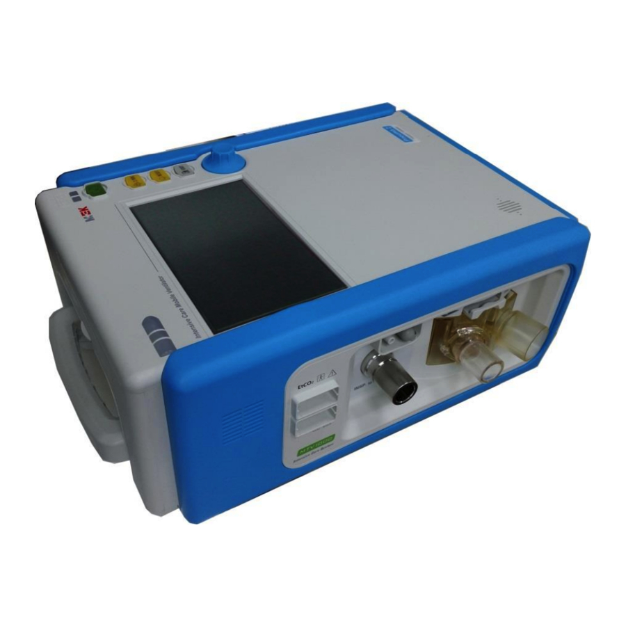
Appearance and Specification This chapter provides information on the appearance and specifications of the MTV1000 ventilator System. 3.1. Overview This product is a ventilator for adults, pediatric, which configures breathing method, tidal volume, Respiratory, oxygen concentration and breathing ratio to resolve the hypoxia shown in pulmonary emphysema or respiratory disease patients. -
Page 12: Appearance
Creates various sounds such as alarms and warnings Alarm Displays alarm status using LED colors Status LED Normal : Green / Alarm : Red, Blue Power Displays power currently used Status LED AC Power : Green / Battery Power : Orange MTV1000 Ventilator System User’s Manual... -
Page 13: Rear View
WARNING Be careful about polarity when replacing the battery. If polarity is reversed, the product can be damaged. Prevent the terminal from contacting metals. For batteries, auxiliary products designated by our company must be used. MTV1000 Ventilator System User’s Manual... -
Page 14: Left Side View
Proximal Connects proximal pressure line Pressure Input Exhalation Drive Line Connects Exhalation Valve Control line Outlet Nebulizer Port Connects Nebulizer Accessory (Option) WARNING If you do not use the Proximal Pressure Port should not cover. MTV1000 Ventilator System User’s Manual... -
Page 15: Right Side View
Connects high pressure oxygen tank Supply Inlet ATTENTION Do not touch RS-232 Port, Video Output Port, USB-A Type Port, and USB-B Type Port with metal substances. Also, turn off the power when connecting cables to these ports. MTV1000 Ventilator System User’s Manual... -
Page 16: Top View
3.2.5. Top View Part Name Description Handle Handle for easy movement of ventilator Port Cover Cover to protect ports for external communication MTV1000 Ventilator System User’s Manual... -
Page 17: Specification
10.8V, 4400mA Li-ion battery 2 EA (Total 8800mAh) Three hours of use under normal operation Charging time: Up to four hours Replaced after two years of use Communication Upgradable (MAIN, Pneumatic board) Display 7” LCD (Resolution: 800 * 480) MTV1000 Ventilator System User’s Manual... -
Page 18: Setting Parameter Specification
Limb Type Dual ± (1.7 + 4% of the actual Pressure Limit 5 ~ 80 cmH 50 cmH reading) cmH V SENS 20 ~ 500 ml 100ml Nebulizer(Option) 10~180min 30 min Trise Fast, Medium, Slow Fast MTV1000 Ventilator System User’s Manual... -
Page 19: Useful Function Description
SpO2 Low(optional) 51 ~ 100% PR High(optional) 26 ~ 250 bpm PR Low(optional) 25 ~ 249 bpm EtCO2 High(optional) 0.0 ~ 15.0 % EtCO2 Low(optional) OFF, O.O ~ 14.9% INS High(optional) 0.0 ~ 15.0 % MTV1000 Ventilator System User’s Manual... -
Page 20: External Specification
International Standards This product selected and acquired the following international standards. EN60601-1:1990 Electric Safety EN60601-1-1:2001 Electromechanical Safety EN60601-1-2:2001 Electromagnetic Compatibility Requirement and tests IEC 60601-2-12:2001 Particular requirements for the safety of lung ventilators for medical MTV1000 Ventilator System User’s Manual... -
Page 21: Internal And External Symbols
Resetting alarm LED and messages Alarm sound Off Alarm sound is off or mute. Touch-key unlocked Enable touch-key function Touch-key locked Disable touch-key function Manual Inspiration Delivering one mandatory inspiration Nebulizer Nebulizer is turned On/Off. (Option) MTV1000 Ventilator System User’s Manual... -
Page 22: Maintenance And Repair
20 minutes at 132˚C. CAUTION Bacteria filters must be replaced to new filters every year or when the number of autoclaves reaches 100. For oxygen sensor, lifespan may be reduced by high FiO or high temperature. MTV1000 Ventilator System User’s Manual... -
Page 23: Cleaning
6. Take care to prevent liquids from entering the product or sensor probe during use. WARNING 1. Do not arbitrarily dispose of the product. 2. Do not discard disposable sensor in places with risks. 3. Be careful about environmental contamination. MTV1000 Ventilator System User’s Manual... -
Page 24: Installation And Set-Up
Power cord must be connected to the outlet attached to the ground. Damaged power cord or sheath must be replaced. When external DC power or AC power is connected, power LED is turned on indicating which power is being supplied. MTV1000 Ventilator System User’s Manual... -
Page 25: External Battery
Use rated voltage of 12V DC and current must be 7A or above. WARNING Fuse is internalized in the product. Time Lag Type, 250V, 6.3A NOTE Internal battery is not charged while external battery is being used. MTV1000 Ventilator System User’s Manual... -
Page 26: Internal Battery
Fuse is internalized in the product. Time Lag Type, 250V, 6.3A Internal battery can be influenced by the number of discharges during use, degree of discharge, surrounding temperature, and charging voltage. Battery can ordinarily be used for two years. MTV1000 Ventilator System User’s Manual... -
Page 27: Power Status Indicator
NOTE When the product is used over two hours with internal battery, ventilator may not operate properly. Measurement values such as TIDAL Volume can be relatively small. MTV1000 Ventilator System User’s Manual... -
Page 28: Internal Battery Replacement Method
WARNING Place battery connector in the correct position when replacing battery. If the connector is misplaced, it may damage the product. CAUTION All bolts are tightened clockwise and loosened counterclockwise. MTV1000 Ventilator System User’s Manual... -
Page 29: Oxygen
Check that high Pressure O supply pressure is appropriate (35~90 PSI). High pressure hose must be kept away from people during use and transportation. If low flow O supply is not used, keep low flow O port closed up. MTV1000 Ventilator System User’s Manual... -
Page 30: Bacteria Filter
When moving the product, keep the LCD frontal. Prior to moving, make sure that parts and power cords are arranged. WARNING When using cart, disable the lock that fixates wheels on the product before movement. Lock the wheels after movement. MTV1000 Ventilator System User’s Manual... -
Page 31: Installation Guide According To Circuit Type
Single limb circuit with Exhalation valve SETUP MODE SETTING SETUP MENU – Limb Type - MASK ON or OFF - Proximal ON/OFF Circuit Type A. Dual limb circuit without external Exhalation Valve (Non-vented Mask Type) MTV1000 Ventilator System User’s Manual... - Page 32 Circuit Type B. Single limb circuit with external Exhalation Valve (Non-vented Mask Type) MTV1000 Ventilator System User’s Manual...
-
Page 33: Getting Started With Mtv1000
5. Getting Started with MTV1000 5.1. General Operation Sequence Item Figure Description Preparing Connect Patient circuit Refer to “Installation Guide according patient circuit appropriate accessories to Circuit Type” and accessories product. A. Connect power cord power inlet. commercial power LED is turned on. - Page 34 Selecting screen. Ventilation B. Select appropriate Mode ventilation mode. more details, refer “Vent. Mode” section. A. Set appropriate Selecting parameters Ventilation selected vent mode. Parameter B. Push accept button to start ventilation. MTV1000 Ventilator System User’s Manual...
-
Page 35: Quick Ventilation Operation Sequence (Dual Ventilation Mode)
Operation Sequence (Dual Ventilation Mode) MTV1000 allows you to save two sets of ventilation parameters. Only physicians and competent nursing, technical staff are permitted to access the clinical screens. The patient must not handle clinical screen directly. 5.2.1. Accessing the quick ventilation mode... -
Page 36: Accessing The Clinical Screens
Clinical Clinical screen will Screen display. A. Select “System” menu -> “Patient” button. Entering B. Input the SVC Code “99”. Quick Mode C. Push “Enter” key. Then Screens ventilator will change the Quick Mode Screens. MTV1000 Ventilator System User’s Manual... -
Page 37: Programming Ventilation Options
5.2.3. Programming ventilation options MTV1000 allows you to save two sets of ventilation parameters. From the main clinical screen you can modify the M1 and M2 ventilation mode. When you have entered a program you can make the desired modifications. There modification is automatically saved when you exit the clinical setting menu. -
Page 38: Quick Ventilation Operation Sequence (Single Ventilation Mode)
Operation Sequence (Single Ventilation Mode) MTV1000 allows you to save two sets of ventilation parameters. Only physicians and competent nursing, technical staff are permitted to access the clinical screens. The patient must not handle clinical screen directly. 5.3.1. Accessing the quick ventilation mode... -
Page 39: Accessing The Clinical Screens
Clinical Clinical screen will Screen display. D. Select “System” menu - > “Patient” button. E. Input Code Entering “99”. Quick Mode Push “Enter” key. Then Screens ventilator will change Quick Mode Screens. MTV1000 Ventilator System User’s Manual... -
Page 40: Programming Ventilation Options
5.3.3. Programming ventilation options MTV1000 allows you to save one set of ventilation parameters. From the main clinical screen you can modify the M1 ventilation mode. When you have entered a program you can make the desired modifications. There modification is automatically saved when you exit the clinical setting menu. -
Page 41: System Management
WARNING Alarm has been occured BLUE CAUTION Once alarm occurs in the device, red light blinking. This light is kept on until user pushed “RESET” button even after the condition is removed. MTV1000 Ventilator System User’s Manual... -
Page 42: Key Pad Description
If AC power is blocked, internal battery starts BATTERY ON LED to operate and “BATTERY ON LED” is turned CAUTION If “AC Power ON LED” and “Battery ON LED” are both OFF, internal battery has run out. MTV1000 Ventilator System User’s Manual... -
Page 43: Vent Mode
Volume Synchronized Intermittent Mandatory Ventilation This mode provides quick start of ventilation based on PBW(Predicted AUTO Body Weight). P-ACV or V-ACV modes are available. NOTE For more details on the mode, refer to Appendix.1 Ventilation Mode Specification MTV1000 Ventilator System User’s Manual... -
Page 44: Modes Available With Single Limb Circuit (External Exhalation Valve)
Volume Synchronized Intermittent Mandatory Ventilation This mode provides quick start of ventilation based on PBW(Predicted AUTO Body Weight). P-ACV or V-ACV modes are available. NOTE For more details on the mode, refer to Appendix.1 Ventilation Mode Specification MTV1000 Ventilator System User’s Manual... -
Page 45: Measurement Information
Measurement information list differs according to the ventilation mode. VT , VE , RATE, , and PEEP are displayed basically. Other information can be checked by selecting “Monitoring” button. Refer to “Monitoring” section for details. Measurement Information MTV1000 Ventilator System User’s Manual... -
Page 46: Graphs
6.4. Graphs Pressure, flow, and volume waves are measured and displayed along with various trend graphs. Display layout can be changed in “Graphics” menu. For more details, refer to “Graphics” section. Wave Graphs MTV1000 Ventilator System User’s Manual... -
Page 47: Alarm Messages
Contact customer service team. occurred. Leakage in circuit. Replace circuit. AIR LEAK Air is leaking. Leakage in block. Contact customer service team. Battery is defective. Replace battery. LOW BATTERY Battery ran out. AC Power loss. Connect AC power MTV1000 Ventilator System User’s Manual... -
Page 48: Ventilation Parameter Setting
V-SIMV VTIDAL, RATE, PEEP, O P-ACV PINSP, RATE, PEEP, O P-SIMV PINSP, RATE, PEEP, O PRVC VTIDAL, RATE, PEEP, O SPONT+ PS, APNEA Time, PEEP, O AUTO Identical to V-ACV Mode or P-ACV Mode Setting. MTV1000 Ventilator System User’s Manual... -
Page 49: Monitoring Menu
I : E Inspiration to expiration ratio Ex.End Flow Expiration flow RSBi b/min/mL Rapid shallow breathing index Oxygen concentration in volume % mL/ cmH Compliance WOBv Work of Breathing Ventilator Pulse Rate SpO2 Oxygen saturation in blood MTV1000 Ventilator System User’s Manual... -
Page 50: E Flow(End Of Exhaled Flow)
Upper figure : It is sufficient exhalation time and lung pressure is the same as PEEP and E_flow is zero. Lower figure : It is insufficient exhalation time and lung pressure is higher than PEEP and E_flow is not zero. MTV1000 Ventilator System User’s Manual... -
Page 51: Graphics Menu
Layout 2 displayed. Among pressure, flow, and volume, one wave graph is displayed with four Layout 3 trend graphs. Trend is saved at every breath. Scrolling interval of the trend graph is adjusted by trend timing. MTV1000 Ventilator System User’s Manual... -
Page 52: Tools Menu
6.9. Tools menu Insp. Hold function can be performed in “Tools” menu. Item Description Compliance, resistance, elastance and time constant of the patient Insp. hold are measured with addition of one second in inspiration hold time. MTV1000 Ventilator System User’s Manual... -
Page 53: Events Menu
“Events” Menu shows all events that occur. Item Description Events relating to changes in ventilation mode and parameter setting Setting are displayed Alarm Events relating to alarm are displayed Both setting events and alarm events are displayed. MTV1000 Ventilator System User’s Manual... -
Page 54: System Menu
-100 ~ 5000 Air Temp 0 ~ 50 Celsius Configure environmental temperature. Configure the use of proximal pressure sensor. Proximal ON / OFF OFF : Proximal Pressure Sensor Off ON : Proximal Pressure Sensor On MTV1000 Ventilator System User’s Manual... -
Page 55: Date
This function compensates for volume of air supplied, considering difference between body temperature and external temperature with altitude above sea level. 6.11.2. DATE Item Description Configure year. Year Month Configure month. Configure day. Configure hour. Hour Minute Configure minute. MTV1000 Ventilator System User’s Manual... -
Page 56: Calibration
Analysis of leakage and compliance is conducted. Leak. Test /OFF CAUTION When performing O calibration, both 21% and 100% must be carried out. CAUTION Before performing Exhalation Flow Auto calibration, inspiration port and expiration port must be connected to tube. MTV1000 Ventilator System User’s Manual... -
Page 57: Patient
Input IP address for external connection using LAN. PORT Input port number for external connection using LAN. SVC Code Configure password for IP and port input. When user attempts to enter a number, the following keyboard appears on the screen. MTV1000 Ventilator System User’s Manual... -
Page 58: Alarm Setting
Configure upper / lower limits for number 0 ~ 150 of breaths per minute. 120, Configure upper lower limits pressure. 100, Configure upper / lower limits for oxygen concentration. 10 ~ 500, Configure difference between inspiratory IR LEAK and expiratory volumes. MTV1000 Ventilator System User’s Manual... - Page 59 EtCO 0 ~ 10 expiratory CO concentration. Configure upper lower limits 0 ~ 10 inspiratory CO concentration. Configure upper / lower limits for number RESP 2 ~ 150 of CO breaths per minute. MTV1000 Ventilator System User’s Manual...
-
Page 60: Useful Hot-Key
Nebulizer about 5~10ml. (Option) It is designed to provide a certain medicine during patient’s inhalation by setting nebulizing time. But you must note that it does not operate in volume ventilation mode of below 200ml. MTV1000 Ventilator System User’s Manual... -
Page 61: Miscellaneous
Miscellaneous I:E Ratio Sound Volume Power Status Item Description Sound Volume Indicate current alarm sound volume setting. Power Status Indicate which power is being supplied. I:E RATIO Ratio of I:E is displayed as a graph. MTV1000 Ventilator System User’s Manual... -
Page 62: Appendix
This condition can also be reached if there is leakage in the breathing system. Triggering will then be initiated by the system and not by the patient. This should always be avoided by decreasing the trigger sensitivity. MTV1000 Ventilator System User’s Manual... -
Page 63: Inspiratory Rise Time
7.1.7. Volume Level Setting During initial setting for each mode of MTV1000 ventilator, volume of air supplied to the patient can be configured by adjusting inspiratory tidal volume. MTV1000 Ventilator System... -
Page 64: Controlled / Supported Pressure Level
Trigger) is not enabled and system be could not go to next Inhalation Phase by ‘En_Sense’ Function. In case, Patient has high airway resistance and too much Ascites(Abdominal Dropsy). The function has another solution to protect retriggering. 7.1.14. Ex_Sense MTV1000 Ventilator System User’s Manual... -
Page 65: Predicted Body Weight
Respiratory volume per minute, tidal volume, breathing rate, etc., the trend is on the basis of height than body weight in general. It becomes the standard of tidal volume multiplied by a BW factor(ml/Kg) and is used to determine proper Respiratory rate per minute. MTV1000 Ventilator System User’s Manual... -
Page 66: Ventilation Modes
Configure inspiration time (patient). Configure sensitivity with which each breath is SENS 10 ~ 80 completed by the patient using % expiration. TRIGGER Pressure/ Configure spontaneous ventilation detection TYPE Flow method as pressure or flow type. MTV1000 Ventilator System User’s Manual... - Page 67 Volume Control assures a preset tidal volume with constant flow during a preset inspiratory time at a preset frequency. When the preset tidal volume is delivered and after the preset pause time. MTV1000 Ventilator System User’s Manual...
- Page 68 I:E ratio is determined by items that influence inspiratory time and by respiratory rate. When changing setting values of I:E ratio or items that influence inspiratory time, breath timing bar is displayed to show changes in cycle time, inspiratory time, expiratory time and I:E ratio. MTV1000 Ventilator System User’s Manual...
-
Page 69: V-Simv(Volume Based Synchronized Intermittent Mandatory Ventilation)
(Ts) begins. If PIM breath does not occur until mandatory interval ends, VIM breath is provided to the patient as soon as mandatory interval ends and spontaneous interval begins. MTV1000 Ventilator System User’s Manual... - Page 70 Choose between TYPE FLOW pressure or flow type. OFF, 0.5 ~ Configure sensitivity detect spontaneous F(P) TRIG ventilation by the patient. Configure pressure supplied to the patient during 0 ~ 60 spontaneous ventilation. MTV1000 Ventilator System User’s Manual...
- Page 71 5 ~ 80 during spontaneous ventilation. MASK ON/OFF Configure mask on / off. ACCEPT Execute V-SIMV Mode. CANCEL Move back to the previous menu. NOTE Default value is configured proportional to body weight of the patient. MTV1000 Ventilator System User’s Manual...
-
Page 72: P-Acv(Pressure Assist Control Ventilation)
21 ~ 100 the patient. Configure sensitivity with which each breath SENS 10 ~ 80 completed by the patient using % expiration. TRIGGER Pressure/ Configure spontaneous ventilation detection method as TYPE Flow pressure or flow type. MTV1000 Ventilator System User’s Manual... - Page 73 It also allows the patient to spontaneously breathe. If the pressure increases to the set upper pressure limit, the expiratory valve opens and the ventilator switches to expiration. MTV1000 Ventilator System User’s Manual...
-
Page 74: P-Simv(Pressure Based Synchronized Intermittent Mandatory Ventilation)
Mandatory Interval ends and Spontaneous Interval (Ts) begins. If PIM breath does not occur until the end of Mandatory Interval, VIM breath is provided to the patient as soon as Mandatory Interval ends and Spontaneous Interval begins. MTV1000 Ventilator System User’s Manual... - Page 75 TRIG ventilation by the patient. Configure pressure supplied to the patient during 0 ~ 60 spontaneous ventilation. MASK ON/OFF Configure mask on / off. ACCEPT Execute P-SIMV Mode. CANCEL Move back to the previous menu. MTV1000 Ventilator System User’s Manual...
-
Page 76: Prvc(Pressure Regulated Volume Control Ventilation)
The first breath of a start sequence is a volume-controlled test breath with pressure of 16cmH O. The measured pause pressure of this breath is then used as the pressure level for the following breath. MTV1000 Ventilator System User’s Manual... - Page 77 Configure pressure limit supplied to the patient P LIMIT 5 ~ 80 during spontaneous ventilation. MASK ON/OFF Configure mask on / off. ACCEPT Execute P-SIMV Mode. CANCEL Move back to the previous menu. MTV1000 Ventilator System User’s Manual...
-
Page 78: Spont+(Spontaneous Ventilation)
Ventilation is operated according to items configured by user and the Respiratory rate is automatically changed to 15 RPM. The mode returns to Spontaneous Mode if the patient shows two spontaneous breaths in 10 seconds. MTV1000 Ventilator System User’s Manual... - Page 79 Configure pressure supplied during inspiration. PINSP APNEA 50 ~ 2500 Volume of the patient at a time MASK ON/OFF Configure mask on / off. ACCEPT Execute SPONT+ Mode. CANCEL Move back to the previous menu. MTV1000 Ventilator System User’s Manual...
-
Page 80: Auto
ACCEPT Execute AUTO Mode. CANCEL Move back to the previous menu. NOTE If you use the Oxygen gas of low flow through the Flowmeter, the effect of oxygenation may be negligible according to High flow. MTV1000 Ventilator System User’s Manual... -
Page 81: Operating Theory
The other is EXP_P4 for expiratory flow measurement. ▣ O gas supply system PV valve controls O gas flow supplied to the tank. ▣ PEEP control system LS1 valve controls positive end-expiratory pressure in the lungs. MTV1000 Ventilator System User’s Manual... -
Page 82: Accessories
Or. No. MA0105_01 Or. No. MA0107_01 Info. Info. Truss head screw M3*10mm Sensor ass'y - Installed Or. No. AS0041_00 Or. No. MA0100_01 Info. Info. User’s Manual Air Filter Or. No. AS0168_00 Or. No. AS0139_00 Info. Info. MTV1000 Ventilator System User’s Manual... - Page 83 PG0032_03 Or. No. PG0032_04 Info. Info. Sensor Extension cable Or. No. AC0007_00 Or. No. AC0145_00 Info. Info. Sensor Extension cable Or. No. PG0022_00 Or. No. AC0124_00 Info. Info. Monitor External Cable Or. No. AC0140_00 Info. MTV1000 Ventilator System User’s Manual...
-
Page 84: Alarm Operation According To Ventilation Mode
7.5. Alarm Operation according to ventilation mode Alarm operation is determined based on ventilation mode. V Tidal V Tidal V Min V Min RATE RATE MODE High High High High High V-ACV V-SIMV SPONT P-ACV P-SIMV PRVC AUTO MTV1000 Ventilator System User’s Manual... -
Page 85: Spo / Etco
SpO /EtCO modules. When the module is attached, SpO /EtCO graph selection menu is added automatically. 7.6.1. / EtCO Connection Information Figure Description Prepare SpO /EtCO Sensor and each extension cable MTV1000 Ventilator System User’s Manual... -
Page 86: Spo 2 / Etco 2 Connection Information
Be careful not to confuse between them when connecting cables. Sensor can be damaged by incorrect connection. Please contact customer service team if the sensor functions improperly after mistaking between two connectors. MTV1000 Ventilator System User’s Manual... - Page 87 Heart rate may be inaccurate in the following situations. ▣ When sensor is tightened too much ▣ When sensor receives excessive medical light, bilirubin light or sunlight ▣ When measured with pressure bandage or at a spot pressured by cuffs MTV1000 Ventilator System User’s Manual...
-
Page 88: Etco 2 Monitoring
Inspiration Setup Connection A. Connect the IRMA analyzer interface cable to the “Gas Extension cable”. Snap the IRMA probe on top of a new IRMA airway adapter. It will click into place when properly seated. MTV1000 Ventilator System User’s Manual... - Page 89 It allows free positioning of the IRMA probe as well. Unless the IRMA probe is protected with an HME always position the IRMA probe with the status LED pointing upwards. MTV1000 Ventilator System User’s Manual...
- Page 90 ▣ Federal law restricts this device to sale by or on the order of a physician. (U.S.) ▣ The IRMA Airway Adapters are non-sterile devices. Do not autoclave the adapters as this will damage them. MTV1000 Ventilator System User’s Manual...
-
Page 91: Test Summary
Guidance and manufacturer’s declaration - electromagnetic emissions The MTV1000 is intended for use in the electromagnetic environment specified below. The customer or the user of the MTV1000 should assure that it is used in such an environment. Emissions test Compliance... -
Page 92: Electromagnetic Immunity
Guidance and manufacturer’s declaration – electromagnetic immunity The MTV1000 is intended for use in the electromagnetic environment specified below. The customer or the user of the MTV1000 should assure that it is used in such an environment. Immunity IEC 60601 test... - Page 93 EUT should be observed to verify normal operation. If abnormal performance is observed, additional measures may be necessary, such as re-orienting or relocating the MTV1000. Over the frequency range 150 kHz to 80MHz, field strengths should be less than [V ] V / m. MTV1000 Ventilator System User’s Manual...
- Page 94 7.7.4. Recommended separation distances The MTV1000 is intended for use in an electromagnetic environment in which radiated RF disturbances are controlled. The customer or the user of the MTV1000 can help Prevent electromagnetic interference by maintaining a minimum distance between portable and mobile RF communications equipment (transmitters) and the MTV1000 as recommended below, according to the maximum output power of the communications equipment.
-
Page 95: Product Warranty Policy
FAX: 070-5052-5800 Web site: http://www.mek-ics.com We are also receiving customer complaints through MEK ICS web site. If you experience any discomforts or improvements to be made on the product, please feel free to contact our company or its customer service team at any time.
Need help?
Do you have a question about the MTV1000 and is the answer not in the manual?
Questions and answers