Table of Contents
Advertisement
Advertisement
Table of Contents

Related Manuals for Vaisala CG31


Summary of Contents for Vaisala CG31
- Page 1 USER'S GUIDE Vaisala Portable Antenna Set CG31 M210843EN-C...
- Page 2 The contents are subject to change without prior notice. Please observe that this manual does not create any legally binding obligations for Vaisala towards the customer or end user. All legally binding commitments and agreements are included exclusively in the applicable supply contract or Conditions of...
-
Page 3: Table Of Contents
Recycling .................. 5 Warranty..................5 Technical Support ..............6 CHAPTER 2 PRODUCT OVERVIEW.................. 7 Introduction to Portable Antenna Set CG31 ......7 Antenna Assembly ..............8 CHAPTER 3 INSTALLATION....................9 Selecting Location ..............9 Assembling the Antenna Set ..........10 Connecting Cables.............. - Page 4 USER'S GUIDE____________________________________________________________________ This page intentionally left blank. 2 ___________________________________________________________________ M210843EN-C...
-
Page 5: Chapter 1 General Information
This chapter provides general notes for the manual and the product. About This Manual This manual provides information for installing, operating, and maintaining Vaisala Antenna Set CG31. Contents of This Manual This manual consists of the following chapters: - Chapter 1, General Information, provides general notes for the manual and the product. -
Page 6: General Safety Considerations
Product Related Safety Precautions The CG31 delivered to you has been tested for safety and approved as shipped from the factory. Note the following precautions: CAUTION Do not modify the unit. Improper modification can damage the product or lead to malfunction. -
Page 7: Esd Protection
Do not dispose of with regular household refuse. Warranty For certain products Vaisala normally gives a limited one-year warranty. Please observe that any such warranty may not be valid in case of damage due to normal wear and tear, exceptional operating conditions, negligent handling or installation, or unauthorized modifications. -
Page 8: Technical Support
If the product needs repair, please follow the instructions below to speed up the process and to avoid extra costs to you. Read the warranty information. Contact Vaisala technical support via e-mail or fax and request for RMA (Return Material Authorization) and shipping instructions. -
Page 9: Chapter 2 Product Overview
The coloring of the parts is adjusted for field operation conditions. One person can transport and assemble the antenna set. Portable Antenna Set CG31 receives radiosonde signals in 400 MHz meteorological range. The antenna set can be used in conjunction with the Vaisala DigiCORA®... -
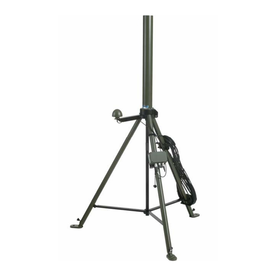
Page 10: Antenna Assembly
USER'S GUIDE____________________________________________________________________ Antenna Assembly The Portable Antenna Set CG31 consists of the following parts: 0704-014 Figure 1 Antenna Set CG31 Assembly The following numbers refer to Figure 1: Helix UHF antenna GPS antenna Antenna Amplifier and Switch RAA111 Tripod Antenna cable UHF/GPS... -
Page 11: Chapter 3 Installation
Install the antenna set on firm ground if possible. If the ground is soft, place the foot pads under the tripod legs to prevent the antenna set from sinking. Although the tripod legs are adjustable, the tripod is more stable when installed on an even surface. VAISALA ________________________________________________________________________ 9... -
Page 12: Assembling The Antenna Set
The tripod legs contain small markings that indicate the location for the top edge of the parts. 0704-015 Figure 2 CG31 Finger Nuts, Peg Hole and Cable Holder The following numbers refer to Figure 2: Finger nut for GPS antenna Finger nut for Helix UHF antenna... - Page 13 Take the tripod out of the transport case and place the tripod in an upright position. Remove the strap that holds the tripod legs together. 0705-194 Figure 3 Removing the Strap Loosen the locking ring with the finger nut. 0705-195 Figure 4 Finger Nut for the Locking Ring VAISALA _______________________________________________________________________ 11...
- Page 14 USER'S GUIDE____________________________________________________________________ Spread the tripod legs and push the locking ring all the way down to the end of the bar. The support bars should be horizontal. 0705-196 Figure 5 Locking Ring Pushed to the End of the Bar Lock the locking ring by tightening the finger nut. 0705-197 Figure 6 Locking the Locking Ring...
- Page 15 - Insert a peg (number 1 in Figure 8) through the hole (number 2 in Figure 8) to the ground to secure the leg. - Repeat this for all legs. - Use the provided hammer to pound the ground pegs in. VAISALA _______________________________________________________________________ 13...
- Page 16 USER'S GUIDE____________________________________________________________________ 0311-049 Figure 8 Attaching Foot Pads Lift the Helix UHF antenna up and lock it by tightening the finger nut. 0705-199 Figure 9 Lifting the Helix UHF Antenna 14 __________________________________________________________________ M210843EN-C...
- Page 17 Wind any extra cable length on the cable holder on the tripod leg in the pattern of figure eight. This will prevent the cable from becoming twisted and difficult to handle. 0705-201 Figure 11 Cable on the Cable Holder VAISALA _______________________________________________________________________ 15...
-
Page 18: Connecting Cables
USER'S GUIDE____________________________________________________________________ Connecting Cables The antenna set is delivered with all the cables connected. It is recommended to store the CG31 with the cables connected. 0705-202 Figure 12 CG31 Cabling The following numbers refer to Figure 12: Cable holder Cable guide... - Page 19 Figure 13 OUT Connector in the Antenna Amplifier and Switch - Connect the UHF antenna cable to the ANT1 connector in the Antenna Amplifier and Switch. 0705-204 Figure 14 ANT1 Connector in the Antenna Amplifier and Switch VAISALA _______________________________________________________________________ 17...
- Page 20 USER'S GUIDE____________________________________________________________________ - Run the cable to the guide on the tripod leg and through the hinge in the Helix UHF antenna. Connect the end of the cable to the connector in the antenna. 0705-205 Figure 15 Connecting the Cable to the Helix UHF Antenna Connect the GPS antenna cable: - Run the GPS part of the dual antenna cable inside the arm of...
-
Page 21: Disassembly For Transportation
NOTE Do not disconnect the cables to the antennas and the Amplifier and Switch. It is recommended to store the CG31 with the cables connected. Loosen the locking ring on the Helix UHF antenna with the finger nut and fold the antenna. - Page 22 Fold the tripod legs together and attach the strap that holds the legs together. 0704-016 Figure 18 CG31 Disassembled for Transportation Place the antenna set in the transport case: - Legs pointing to the wheels of the transport case - GPS antenna pointing upwards Refer to Figure 19 for the correct placement of the antenna set in the transport case.
-
Page 23: Maintenance
Figure 19 CG31 Packed for Transportation Maintenance Under normal conditions, the CG31 needs only a minimal amount of maintenance. - Clean the antenna set regularly by removing excess dirt and dust. - Inspect the cables for breaks, cracks in the protective coating or connectors, and bent or damaged pins. - Page 24 USER'S GUIDE____________________________________________________________________ This page intentionally left blank. 22 __________________________________________________________________ M210843EN-C...
-
Page 25: Technical Specifications
35 dB (nominal) Noise 2.75 dB (nominal) Pass-band width 50 MHz Azimuth coverage 360° (omni-directional) Elevation coverage 0° to 90° elevation (hemispherical) Mechanics Connector UHF Antenna: Coaxial N-type female GPS Antenna: Coaxial TNC-type female Diameter assembled 1133 mm VAISALA _______________________________________________________________________ 23... - Page 26 USER'S GUIDE____________________________________________________________________ Property Value Total height assembled 1695 mm Transportation case dimensions 1380 x 355 x 385 mm Weight (antenna set / including case) 10.5 kg / 23.5 kg Standard cable length 20 m Environmental conditions Operating temperature range -40 ... 55° C Operating humidity range 0 …...
-
Page 27: Chapter 5 Parts List
Chapter 5 _________________________________________________________________ Parts list CHAPTER 5 PARTS LIST This chapter contains the spare parts list for the antenna set. Table 3 Spare Parts List for Portable Antenna Set CG31 Part no. Item Quantity DRW220676 Tripod for CG31 DRW224063 Antenna Cable, Dual UHF/GPS 20m... - Page 28 USER'S GUIDE____________________________________________________________________ This page intentionally left blank. 26 __________________________________________________________________ M210843EN-C...
- Page 29 www.vaisala.com...
Need help?
Do you have a question about the CG31 and is the answer not in the manual?
Questions and answers