Table of Contents
Advertisement
Quick Links
Advertisement
Table of Contents

Summary of Contents for CWT GFM A0A0161
- Page 1 Computer Weld Technology, Inc. 10702 Old Bammel N Houston Rd. Houston, TX 77086 Phone: (713) 462-2118 Fax: (713) 462-2503 Email: cwt@cweldtech.com GFM Gas Flow Monitor Operation / Installation Manual Manual Part Number: A8M5028 Revised: 01/23/2017...
- Page 3 SAFETY PRECAUTIONS – READ BEFORE USING Welding is not particularly hazardous when certain safety practices are followed. Everyone using this equipment should be thoroughly trained in safe welding practices. Failure to observe safe practices may cause serious injury. Handling welding torches presents no danger if the appropriate safety regulations are strictly adhered to.
- Page 4 • Do not weld or cut in locations near degreasing, cleaning, or spraying operations. The heat and rays of the arc can react with vapors to form highly toxic and irritating gases. • Do not weld or cut on coated metals, such as galvanized, lead, or cadmium plated steel, unless the coating is removed from the weld area, the area is well ventilated, and while wearing an air supplied respirator.
- Page 5 • After completion of work, inspect area to ensure it is free of sparks, glowing embers, and flames. • Use only correct fuses or circuit breakers. Do not oversize or by-pass them. • Follow requirements in OSHA 1910.252 (a) (2) (iv) and NFPA 51B for hot work and have a fire watcher and extinguisher nearby.
- Page 6 • Insulate work clamp when not connected to workpiece to prevent contact with any metal object. • Do not connect more than one electrode or work cable to any single weld output terminal. Disconnect cable for process when not in use. Cylinders Compressed gas cylinders contain gas under high pressure.
- Page 7 Additional Safety Warnings for Installation, Operation and Maintenance READ INSTRUCTIONS • Read and follow all labels and the Owner’s Manual carefully before installing, operating, or servicing the unit. • Read the safety information at the beginning of the manual and each section.
- Page 8 5. Connect work clamp to workpiece as close to the weld as possible. 6. Do not work next to, sit or lean on the welding power source. 7. Do not weld while carrying the welding power source wire feeder. About Implanted Medical Devices: Implanted Medical Device wearers should consult their doctor and the device manufacturer before performing or going near arc welding, spot welding, gouging, plasma arc cutting, or induction heating operations.
-
Page 9: Table Of Contents
Table of Contents OVERVIEW ........................1 SYSTEM REQUIREMENTS ........................1 BENEFITS ..............................1 FEATURES ..............................1 MECHANICAL SPECIFICATIONS ......................1 SENSOR SPECIFICATIONS ........................2 MODELS ...............................2 INSTALLATION ......................3 OPTIONS ..............................3 GAS LINE HOOKUP ............................3 CABLE HOOKUP ............................3 GAS FLOW LIMITS ............................4 GAS FLOW VOLUME ..........................4 OPERATION ........................ - Page 10 10.0 GFM ENCLOSURE SPECIFICATIONS ..............23 10.1 GFM ENCLOSURE PARTS LIST ......................23 10.2 GFM MOUNTING DIMENSIONS ......................24 11.0 CABLE SPECIFCATIONS ..................26 11.1 GFM AUX CABLE P/N: A3W0352 ......................26 11.2 ADM III GFM SENSOR CABLE P/N: A3W0356 ................27 11.3 ADM IV...
-
Page 11: Overview
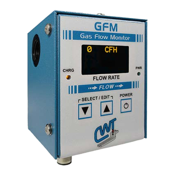
1.0 OVERVIEW Description The Gas Flow Monitor (GFM) is designed to precisely measure the flow rates of welding shielding gases. WARNING – DO NOT USE WITH ANY FLAMMABLE GASES. The unit comes in both "portable" and "in-line" models and is software configurable for English or Metric units of measure. -
Page 12: Sensor Specifications
Sensor Specifications Measurement Range 5 - 255 CFH (2 - 120 LPM) Display Resolution ±1 CFH (± 1 LPM) Accuracy ±3 % of full-scale ±1 digit Operating Pressure 50-PSI maximum (344 KPA) Fault Relay Output Opto-Isolated Solid State Relay (N.O. Contacts) Relay Rating 48 vac @ 0.5 amps non-inductive 48 vdc @ 1.0 amps non-inductive... -
Page 13: Installation
2.0 INSTALLATION Options The GFM can be used as a portable or in-line gas flow monitor. If the unit was purchased as a portable monitor, it will be equipped with a rubber gas cone. When installing the rubber hose and gas cone on the GFM make sure the hose is installed on the side of the GFM... -
Page 14: Gas Flow Limits
The output impedance of this signal is 100 ohms and can source 10 milliamps of current. The analog-interface cable can also be used to supply power to the GFM. The power requirement is (12 - 28) vdc @ 100 ma. This cable also has the connections for the Fault Relay and Modbus®... -
Page 15: Operation
3.0 OPERATION Firmware Version The GFM is supplied with a plug-in the wall transformer, which powers the GFM and will also charge the optional internal battery. Plug the transformer into a suitable ac receptacle, and connect the power cable into the "POWER" jack located on the bottom panel of the GFM. -
Page 16: Parameters
Parameters The following is the list of the parameters and system configurations that can be modified by the user: • Max Limit= ### - Maximum gas flow Limits. This value is used to set the high fault alarm and disable the output alarm. This value is also used to trigger the Peak Flow detector. - Page 17 • DEVICE ID= - This parameter sets the Modbus address ID number for the GFM. This address is used to identify the Device when using the Modbus® serial communications protocol. Each sensor connected to the Modbus® network must have a unique ID number assigned. (Value Range 1 to 247) •...
- Page 18 80/20 Argon/ CO Gas conversion factor. (Status Yes or No) Note: Disabling All Gas types (set to NO) will enable the Air conversion factor. • 90/10 Argon/ CO Gas? - Allows the user to enable or disable 90/10 Argon/ Gas conversion factor. Setting this option to “No” will disable the 90/10 Argon/ CO Gas conversion factor.
-
Page 19: Setting Gas Flow Control Limits
4.0 SETTING GAS FLOW CONTROL LIMITS Description To use the GFM as a Sure-Flow gas switch, the user can set the “Max Limit” and “Min Limit”. The GFM will activate the internal fault relay as long as the gas flow remains above the lower limit and below the upper limit. -
Page 20: Gas Flow Surge "Peak" Measurement
5.0 GAS FLOW SURGE “PEAK” MEASUREMENT Description The GFM has a peak value "sample and hold" feature. This allows the user to measure the maximum gas flow rate, which occurred during the welding cycle. The maximum value is the result of a gas surge, which occurs when the gas solenoid is activated. -
Page 21: Gas Flow Usage Log
6.0 GAS FLOW USAGE LOG Description The GFM has a gas flow volume accumulator and gas flow accumulated timer which can be used to display total gas usage and Total gas flow Time. This function allows the user to measure the total cubic ft. or liters of gas used from the last time that the accumulator was reset. -
Page 22: Reset Log Mode Volume
Reset Log mode volume To reset the Log mode volume press both “▼” and "▲" switch simultaneously to enter the “Select Para INC/DEC” mode. The first programmable parameter will appear on the display. To increment through the program menus press the “▲” button. -
Page 23: Gfm Connector Pin Assignment
7.0 GFM CONNECTOR PIN ASSIGNMENT AUX Connector The following is the pin out for the AUX Connector. Pin No. Function 1 (WHT) Modbus RS-485 D+ serial port 2 (BRN) User supplied Power Input VIN+ (12-28 VDC @100 ma) 3 (GRN) CR-A - Will be active when gas flow is within programmed limits. -
Page 24: Power Options And Battery Specification/Changing
8.0 POWER OPTIONS AND BATTERY SPECIFICATION/CHANGING Power Options The GFM can be used as a Battery Powered device or installed in-line and powered from a Plug-in Wall power supply or user supplied 12 - 24 vdc power supply. 8.1.1 Power Board – Revision: 0 By default the jumper on Header “JP1”... - Page 25 8.1.2 Power Board – Revision: A By default the jumper on Header “JP1” is installed on Location “A” for “Manual” function. This will enable the power switch whenever the battery is being used as the power source. When the jumper is on Location “B”, this sets the “Auto” function. This disables the power switch for whenever the external power is applied through the Power Connector or Aux Connector keeping the GFM always turned on.
-
Page 26: Battery Specifications
Battery Specifications The portable GFM is supplied with an internal, rechargeable battery. The battery will operate the GFM continuously for approximately 24 hours when fully charged. The supplied plug-in the wall transformer will recharge the battery in approximately 8-10 hours. The GFM can be operated while charging the battery. The battery charge status is displayed by the “CHRG”... - Page 27 Trim back the two cable ties. • Connect the two circuit plug of the battery to J3 Battery Header on the Power Board. 4. Reinstall the cover and the six screws. CWT Replacement Part - P/N: A3A0278 (4.1V rechargeable battery) Cable Tie Mounts Cable...
-
Page 28: Model Specifications
9.0 MODEL SPECIFICATIONS 120/240 VAC Portable GFM System P/N: A0A0161 ITEM PART NO DESCRIPTION A3A0277 GFM Enclosure Assembly A3A0278 Rechargeable Battery A2M0170 Hose/Cone Assembly X3T5089 12VDC Universal Switching Power Supply... -
Page 29: 120/240 Vac In-Line Gfm System P/N: A0A0162
120/240 VAC In-Line GFM System P/N: A0A0162 ITEM PART NO DESCRIPTION A3A0277 GFM Enclosure Assembly A3E0104 GFM Mounting Bar X3T5089 12VDC Universal Switching Power Supply X6F5093 Adaptor Fitting X6F5094 Barb Fitting X6F5095 "B" Size Nut #10-32 x 1/2" Lg. Socket Flat Hd. Screw... -
Page 30: Adm Iii Gfm System P/N: A0A0163
ADM III GFM System P/N: A0A0163 ITEM PART NO DESCRIPTION A3A0277 GFM Enclosure Assembly A3E0104 GFM Mounting Bar A3W0356 ADM3 – GFM Sensor Cable X6F5093 Adaptor Fitting X6F5094 Barb Fitting X6F5095 "B" Size Nut #10-32 x 1/2" Lg. Socket Flat Hd. Screw... -
Page 31: Adm Iv Gfm System P/N: A0A0164
ADM IV GFM System P/N: A0A0164 ITEM PART NO DESCRIPTION A3A0277 GFM Enclosure Assembly A3E0104 GFM Mounting Bar A3W0350 ADM4 – GFM Sensor Cable X6F5093 Adaptor Fitting X6F5094 Barb Fitting X6F5095 "B" Size Nut #10-32 x 1/2" Lg. Socket Flat Hd. Screw... -
Page 32: Wdl Ii Gfm System P/N: A0A0165
WDL II GFM System P/N: A0A0165 ITEM PART NO DESCRIPTION A3A0277 GFM Enclosure Assembly A3E0104 GFM Mounting Bar A3W0351 WDL2 – GFM Sensor Cable X6F5093 Adaptor Fitting X6F5094 Barb Fitting X6F5095 "B" Size Nut #10-32 x 1/2" Lg. Socket Flat Hd. Screw... -
Page 33: Gfm Enclosure Specifications
10.0 GFM ENCLOSURE SPECIFICATIONS 10.1 GFM Enclosure Parts List ITEM PART NO DESCRIPTION A3E0190 GFM Enclosure Base A3E0191 GFM Enclosure Cover A3E0192 GFM Enclosure Overlay A3E0179 GFM Display Lens A5A0165 GFM CPU PCB Assembly A5A0166 GFM Power PCB Assembly A5A0167 GFM Display PCB Assembly A3W0366 GFM Sensor Harness... -
Page 34: Gfm Mounting Dimensions
10.2 GFM Mounting Dimensions Installation with Threaded Inserts or Free Hanging... - Page 35 Installation with Mounting Bar...
-
Page 36: Cable Specifcations
11.0 CABLE SPECIFCATIONS 11.1 GFM Aux Cable P/N: A3W0352 ITEM PART NO DESCRIPTION X3W5118 8 Conductor Shielded Cable Cable Label Sleeve Wire Label Sleeve Heat Shrink Tubing WIRE COLOR FROM DESCRIPTION White Pin 1 Net+ Brown Pin 2 Power In (12 – 28 VDC) Green Pin 3 Relay CR-A... -
Page 37: Adm Iii Gfm Sensor Cable P/N: A3W0356
11.2 ADM III GFM Sensor Cable P/N: A3W0356 ITEM PART NO DESCRIPTION X3W5118 8 Conductor Shielded Cable X3P5459 Plug 5 Circuit Connector Cable Label Sleeve WIRE COLOR FROM DESCRIPTION White Item 1 Pin 1 Not Connected Net+ Brown Item 1 Pin 2 Item 2 Pin 1 Power In (12 –... -
Page 38: Adm Iv Gfm Sensor Cable P/N: A3W0350
11.3 ADM IV GFM Sensor Cable P/N: A3W0350 ITEM PART NO DESCRIPTION X3W5118 8 Conductor Shielded Cable X3P5606 Plug 6 Circuit Connector X3P5588 Cable Clamp Cable Label Sleeve Heat Shrink Tubing WIRE COLOR FROM DESCRIPTION White Item 1 Pin 1 Not Connected Net+ Brown... -
Page 39: Wdl Ii Gfm Sensor Cable P/N: A3W0351
11.4 WDL II GFM Sensor Cable P/N: A3W0351 ITEM PART NO DESCRIPTION X3W5118 8 Conductor Shielded Cable X3P5682 Plug 6 Circuit Connector X3P5629 Yellow Strain Relief Cable Label Sleeve WIRE COLOR FROM DESCRIPTION White Item 1 Pin 1 Not Connected Net+ Brown Item 1 Pin 2... -
Page 40: Modbus Scpecifications
12.0 MODBUS SCPECIFICATIONS 12.1 GFM MODBUS REGISTER DATA This document provides the basic Modbus memory map and command structure for the GFM RS-485 communications port. The GFM supports the Modbus Protocol as specified in the Modicon Technical publications “Modbus Protocol” (intr7.html). The GFM control does not support the Broadcast mode. -
Page 41: Modbus Register Reg [1
12.3 MODBUS REGISTER REG [1..10] REG NO. MNEMONIC FORMAT PARAMETER DESCRITION GASFLOW Gas flow rate MAXLMT Max Gas Flow Alarm Limit MINLMT Low Gas flow Alarm Limit MINVOL #### Low Volume Alarm (Not Enabled) ACCVOL ####.# Accumulated Gas Flow since last reset RTCHR ##### Total Gas Flow hours since last reset...
Need help?
Do you have a question about the GFM A0A0161 and is the answer not in the manual?
Questions and answers