Table of Contents
Advertisement
Quick Links
Advertisement
Table of Contents

Summary of Contents for ATWELL UMD-SRB01
- Page 1 Uncontrolled Movement Detector Uncontrolled Movement Detector for Bi Directional Rope Brakes for Bi Directional Rope Brakes Installation Manual Installation Manual Version 4.0 Includes New Wiring Version 4.0 Includes New Wiring Serving the lift industry since 1996 Operation and Installation Manual...
-
Page 2: Table Of Contents
Signals ........................7 Operational Flow Chart ..................8 Handling, transport and storage ................10 Components supplied .....................10 Installation........................11 General Advice ....................11 The Control Box (UMD-SRB01) ................11 Wiring ........................12 Mechanical Installation ...................18 Normal Operation ....................19 Resetting the System ..................19 Bypassing the System ..................20 Test Deployment of brakes ................21 Uncontrolled Movement Settings ................22... -
Page 3: Overview
During this time whilst the doors are open the system will continue to detect excessive movement. Atwell International Limited... -
Page 4: Safety Notes
No replacement parts other than those specified or supplied by the supplier Atwell International should be used as incompatible parts may risk the safe operation of the lift. Genuine spares are available within 24 hours at a reasonable cost. -
Page 5: Owners Obligations
This Warning Label is incorporated into the control box lid graphic to warn you of Live Electrical Parts, DO NOT REMOVE the lid if you are not a competent electrician capable of safely assessing the potentially dangerous internal connections. Atwell International Limited... -
Page 6: Specification
Maintenance, other than checking cleanliness of idler pulley assembly, is not required for the actual components of the system, but it will be strongly recommended that the operation is regularly checked and tested by competent persons (lift engineer) to comply with the regulations. UMD-SRB01 Version 4... -
Page 7: The System
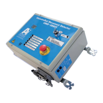
It contains a programmable safety device, display, visual and audible indicators, key switch, battery, power supply and fuses. The UMD-SRB01 controller has been designed and constructed to comply with all current CE requirements, i.e. EMC, Low Voltage, RoHS, WEEE and more specifically to meet the requirements of EN 81-80: 2003 5.9.4 Uncontrolled Movement with... -
Page 8: Signals
In addition to this there is a small visual display showing a text interface explaining the status and warnings. The UMD-SRB01 has two switches, one is an emergency stop button which when pressed will immediately deploy the brakes. The other switch requires a key to operate it, this is because regulations require a competent person to reset the brakes in the event of them being deployed. -
Page 9: Operational Flow Chart
Atwell Uncontrolled Movement Detector and System Status System S Status Status (Fully Reset, brakes set, doors closed, key in RUN position, safety circuits OK (Fully Rest, brakes set, doors closed, key in RUN position, safety cir CHANGE IN STA Door(s) Opens... - Page 10 50 mm to 150 mm level of movement will deploy brakes As soon as the doors open the brakes will be deployed Mar 08 UMD-SRB01 Version 4...
-
Page 11: Handling, Transport And Storage
If the Brakes, Cables, Controller or Sensor has been or suspected to have been damaged or exposed to moisture, they should not be used. Please return them to Atwell International for examination and re-test. The brakes, control boxes or sensors should never be lifted or carried by their cables. -
Page 12: Installation
Specific hazards arise for inadequate lighting, untidy work area, trip hazards and poor access. The Control Box (UMD-SRB01) It is recommended that the Control box is ideally mounted at approx 1.5 metres high on to a solid wall adjacent to the main lift control panel and close to the rope brake and monitoring pulley position. -
Page 13: Wiring
The 32-way connector is fitted so as to prevent the need for access inside of the control box. If you should need access to the inside of the control box please contact Atwell International for written consent as your warranty may be invalidated if the internal seals are broken. - Page 14 UMD-SRB01 enclosure and the terminal housing even when the fuses for the enclosure have been withdrawn. Within the UMD-SRB01 enclosure the internal connecting cables are coloured orange, this is so that you can easily identify them as potentially live, check them and beware of them.
- Page 15 In addition, a connection directly to the normally closed (when not in over speed condition) over speed governor switch is required. The operation of these switches is essential to enable the UMD-SRB01 to operate safely, i.e. If a cable is broken or the lift over speeds the UMD-SB01 will be FAIL SAFE.
- Page 16 8 core cable (in case of future mods) 8 core cable Cable screen sheathed and terminated to earth Screened cable connected with main earth cable Black wire removed to show correct use of boot lace crimps UMD-SRB01 Version 4...
- Page 17 Wiring (continued) 16 Atwell International Limited...
- Page 18 UMD-SRB01 Version 4...
-
Page 19: Mechanical Installation
Check for smooth operation and no excessive play or run out. Connect the other end of this sensor cable to the UMD-SRB01 panel via the 32 way connector, if you have not done so yet. 18 Atwell International Limited... -
Page 20: Normal Operation
Warning the safety devices controlled by this controller are bypassed while the key is in this position. The rope brakes will require lifting into position, and then they will hold there. System is now SET. Return key to central RUN position. UMD-SRB01 Version 4... -
Page 21: Bypassing The System
“ENGINEER BYPASS MODE”. Warning the safety devices controlled by this controller are bypassed while the key is in this position. To get back to a normal running mode. Return key to central RUN position. 20 Atwell International Limited... -
Page 22: Test Deployment Of Brakes
Turn key switch to reset. Lift up both rope brakes Return key switch to run position. Please note the Key is retained in either Test or reset positions. It can only be removed when in the normal run position. UMD-SRB01 Version 4... -
Page 23: Uncontrolled Movement Settings
Uncontrolled Movement The UMD-SRB01 control box has factory set coding that allows it to receive 2 types of pulse counts from the UMD-SP01, these are the slow speed count Settings and the high speed count. The reason for this is to provide 2 different types of movement detection. -
Page 24: Instructions For Rescue Operations
3. Investigate reason for engagement and carry out appropriate action. 4. Read local hand winding instructions. 5. On the “UMD-SRB01” control panel insert the key and turn to the “RESET” position. Note: An audible alarm will sound until the key is returned to the “Run” position. -
Page 25: Regular Maintenance
No replacement parts other than those specified or supplied by the supplier (Atwell International) should be used as incompatible parts may risk the safe operation of the lift. Genuine spares are available within 24 hours at a reasonable... -
Page 26: Maintenance Instructions
If during the routine visits it is apparent that there are any signs of damage or wear or abuse of any of the components of the system, then you must remove the lift from service until the faults are remedied and the installation is tested by a competent person. UMD-SRB01 Version 4... -
Page 27: Spare Parts
General Information Electrical Supply Voltage 230V +/-10% Number of Phases Single Phase, Neutral and Earth Frequency 50 / 60 Hz Full Load Current 2.5 A Normal Running Current 1.25A Type Of Safety Component Bi-Directional Rope Brake. 26 Atwell International Limited... -
Page 28: Definitions
Replacement or repair of defective and/or worn components. Safety Components Components which are defined as safety components in the EU Lifts Directive (2014/33/EU). Competent Maintenance Person Persons with the knowledge, technical ability and equipment able to perform the tasks allocated to them without danger. UMD-SRB01 Version 4... -
Page 29: Very Important
EPROM upgrade for you at a minimal charge. This will ensure the system is to current standards and you maintain all warranties. You must however inform Atwell if you plan to use or have used this upgrade at other sites. -
Page 30: Pulse Count Table
2.75 2749 2.83 2828 2.91 2906 2.98 2985 3.06 3063 1000 3.14 3142 1025 3.22 3221 1050 3.30 3299 1075 3.38 3378 1100 3.46 3456 1125 3.53 3535 1150 3.61 3613 1175 3.69 3692 1200 3.77 3770 UMD-SRB01 Version 4... - Page 31 • Divertors • Overspeed Governors • Tension Weights Sliding Guide Shoes • Guide Rails • Buffers • Compensation Chains Atwell International Ltd Ball Mill Top Business Park Hallow Worcester WR2 6PD United Kingdom Telephone +44 (0)1905 641881 info@atwellinternational.com Copyright© Atwell International Limited. All rights reserved.
Need help?
Do you have a question about the UMD-SRB01 and is the answer not in the manual?
Questions and answers