Advertisement
Quick Links
READ ALL WARNINGS AND INSTRUCTIONS BEFORE BEGINNING THIS INSTALLATION.
WARNING: FAILURE TO FOLLOW THESE INSTRUCTIONS COULD RESULT IN SERIOUS
INJURY OR DEATH.
1.
This unit has an unguarded impeller and may start unexpectedly.
2.
Turn off all power to fan before performing any maintenance. The motor
may start automatically. The motor is equipped with an automatic overload
protection. If the motor overheats and stops, it will re-start automatically
when it cools.
3.
Before servicing or cleaning this unit, switch power off at the service panel
and lock out to prevent power from being switched on accidentally. When
service disconnecting means cannot be locked, securely fasten a prominent
warning tag to the service panel.
DANGER
WARNING
CAUTION
ELECTRICAL SHOCK
Ventamatic, Ltd.
1-800-433-1626
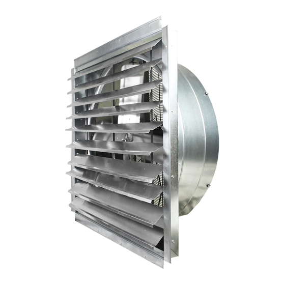
Exhaust Fan IF Series
CAUTION
SAFETY
This safety alert symbol is used to alert you to
potential personal injury hazards. Obey all safetry
messages that follow this symbol to avoid possible
injury or death.
Danger indicates an imminently hazardous situation, which, if not
avoided, will result in death or serious injury.
Warning indicates a potentially hazardous situation, which, if not
avoided, could result in death or serious injury.
Caution indicates a potentially hazardous situation, which, if not
avoided, may result in minor or moderate injury.
Used to indicate an electrical shock or electrocution hazard.
P.O. Box 728, Mineral Wells, TX 76068-0728
Fax: 940.325.9311
Replacement Louver Kit
Installation Instructions
Louver Replacement Kits
IF14, IF18, IF24, IF30, IF36
www.BVC.com
©2019 VENTAMATIC, LTD. IF REpLACEMENT LouVER KIT INS 1219/1116
Advertisement

Related Manuals for Maxx air IF Series


Summary of Contents for Maxx air IF Series
- Page 1 Exhaust Fan IF Series Replacement Louver Kit Installation Instructions Louver Replacement Kits IF14, IF18, IF24, IF30, IF36 READ ALL WARNINGS AND INSTRUCTIONS BEFORE BEGINNING THIS INSTALLATION. WARNING: FAILURE TO FOLLOW THESE INSTRUCTIONS COULD RESULT IN SERIOUS INJURY OR DEATH. CAUTION This unit has an unguarded impeller and may start unexpectedly.
- Page 2 INSTRUCTIONS 1. Lift louver vane above the damaged louver vane to be replaced. This will give better access to the linkage pins that need to be removed on the damaged louver vane. (Fig.1 & 2) 2. Using a standard (flat- Fig.1 - Damaged louver vane needs head) screwdriver, press replacing...
- Page 3 side that had the screws removed (either left or right) until the nylon pivot screw heads are exposed. (Fig.4 & 5) 4. Using a screwdriver, back the pivot screw out from the nylon pivot nut and Fig.4 - Remove unit mounting screws the louver vane.
- Page 4 6. Hold the louver vane in place while re-inserting the remaining pivot screw. Again, it may be necessary to hold the pivot nut in place with another tool while tightening the pivot screw. 7. Push the IF unit back into place against the wall and Fig.7 - Louver hinge slides over nylon reattach using the screws...