Table of Contents
Advertisement
Available languages
Available languages
Advertisement
Chapters
Table of Contents

Summary of Contents for Michael Riedel RDCUSV C Series
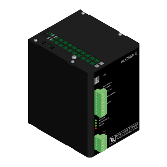
- Page 1 DC-USV-Kondensator-Module Baureihe RDCUSV C Betriebsanleitung Michael Riedel Transformatorenbau GmbH · Max-Eyth-Straße 10 · D-74532 Ilshofen-Eckartshausen Telefon (07904) 704-0 · Fax (07904) 70450 · www.riedel-trafobau.de · info@riedel-trafobau.de...
-
Page 2: Table Of Contents
InhaltSVeRzeIChnIS allgeMeIneS allgeMeIne SICheRheItShInweISe KURzBeSChReIBUng Montage UnD anSChlUSS Montage aBMeSSUngen anSChlUSS PRInzIPSChaltBIlD InBetRIeBnahMe anzeIgen UnD MelDUngen BetRIeB PUffeRBetRIeB ShUt-Down InStanDhaltUng aUSSeRBetRIeBnahMe noRMen UnD VoRSChRIften teChnISChe Daten eInSChaltDaUeR BeReChnUng DeR PUffeRzeIt leBenSDaUeR DeR KonDenSatoRen DaTEI: BEDIEnunGSanlEITunG RDCuSV-C STanD 16. Jun 2011 kurzfristig lieferbar Technische Änderungen vorbehalten... -
Page 3: Allgemeines
allgeMeIneS Das DC-Puffermodul ist im bestimmungsgemäßen Gebrauch für die Überbrückung einer DC-Spannungsversorgung bei Spannungs- ausfall bestimmt. Das Puffermodul wird hierzu von einem externen, geregelten DC-netzteil aufgeladen. allgeMeIne SICheRheItShInweISe hinweis Vor der Installation bzw. Benutzung der Stromversorgung ist die Bedienungsanleitung zu lesen. Die anwei- sungen sind einzuhalten. -
Page 4: Abmessungen
aBMeSSUngen RDCUSV 3C1 RDCUSV 5C5 RDCUSV 10C10 RDCUSV 20C8 höhe (h) Breite (B) einbautiefe (t) anSChlUSS Vor dem anschluss sind die Werte der DC-Versorgung mit den Werten des Typenschildes auf Übereinstimmung zu prüfen. anschluss gemäß den Bezeichnungen der anschlussklemmen vornehmen (siehe Prinzipschaltbild und anschlussbelegung ) anschluss: Klemme: anschluss:... -
Page 5: Prinzipschaltbild
PRInzIPSChaltBIlD RDCuSV 3C1 RDCuSV 5C5 DC-DC-Wandler DC-DC-Wandler LED1 LAST µC Betrieb LED1 SHUT-DOWN LAST Betrieb µC LED2 DC 30V/0,5A UE-o.k. Ue-o.k. LED3 DC 30V/0,5A UC> DC 30V LED2 0,5A DC 30V/0,5A Fehler LED3 LED4 Uc> RDCuSV 10C10 RDCuSV 20C8 DC-DC-Wandler DC-Wandler LED1 LAST... -
Page 6: Betrieb
BetRIeB nach dem Einschalten der uE wird die Versorgungsspannung ausgemessen und automatisch die entsprechende Systemspannung 12V oder 24V gewählt. Ca. 1,5 Sekunden nach dem Einschalten wird die ausgangsspannung freigegeben und die angeschlossenen Verbraucher werden versorgt. Ebenso erfolgt die ladung des Pufferkondensators. Diese Betriebsart wird durch das leuchten der grünen lED ‘uE-o.k.’... -
Page 7: Technische Daten
teChnISChe Daten kurzfristig lieferbar Technische Änderungen vorbehalten... -
Page 8: Einschaltdauer
eInSChaltDaUeR Einschaltdauer in abhängigkeit des laststromes und der umgebungstemperatur Bereich 2 Für die Betrachtung der Einschaltdauer sind nur die lade- und Entladezyklen der Kon- 50% ED densatoren relevant. Ist das Puffermodul aufgeladen und arbeitet im Standbymodus tritt keine Erwärmung des Gerätes auf. Dieser Fall ist somit thermisch mit einem ausge- schalteten Gerät gleichzusetzen. - Page 9 DC UPS Capacitor Module RDCUSV C Series Operating manual Michael Riedel Transformatorenbau GmbH · Max-Eyth-Straße 10 · D-74532 Ilshofen-Eckartshausen Telefon (07904) 704-0 · Fax (07904) 70450 · www.riedel-trafobau.de · info@riedel-trafobau.de...
- Page 10 TABLE OF CONTENTS GENERAL INFORMATION GENERAL SAFETY INSTRUCTIONS SHORT DESCRIPTION ASSEMBLY AND CONNECTION ASSEMBLY DIMENSIONS CONNECTION PRINCIPLE CIRCUIT DIAGRAM INITIAL OPERATION DISPLAYS AND MESSAGES OPERATION BACK-UP MODE SHUT-DOwN MAINTENANCE SHUTDOwN STANDARDS AND REGULATIONS TECHNICAL DATA DUTY CYCLE CALCULATION OF BACK-UP TIME CAPACITOR LIFE FIlE: BEDIEnunGSanlEITunG RDCuSV-C DaTED 16.
-
Page 11: General Information
SHORT DESCRIPTION The RDCuSV C series DC back-up module has an ultracapacitor as an energy storage device inside the enclosure. This capacitor is charged during normal operation by an external regulated DC power supply unit. If the DC supply is interrupted the energy of the ultracapacitors is released in a controlled manner. -
Page 12: Dimensions
DIMENSIONS: Type RDCUSV 3C1 RDCUSV 5C5 RDCUSV 10C10 RDCUSV 20C8 Height (H) width (w) Installation depth (T) CONNECTION Before connection ensure the values of the DC supply match the values on the rating plate. Carry out the connection according to the designations on the connection terminals (see circuit diagram and terminal assignment). -
Page 13: Principle Circuit Diagram
PRINCIPLE CIRCUIT DIAGRAM RDCuSV 3C1 RDCuSV 5C5 DC-DC converter DC-DC converter LED1 LAST µC Operation LED1 SHUT-DOWN LAST Operation µC LED2 DC 30V/0,5A IV-o.k. IV-o.k. DC 30V LED3 DC 30V/0,5A UC> LED2 0,5A LED3 Uc> LED4 DC 30V/0,5A Error RDCuSV 10C10 RDCuSV 20C8 DC-DC converter DC converter... -
Page 14: Operation
OPERATION after the input voltage (IV) is switched on the supply voltage is measured and the corresponding system voltage (12V or 24V) is auto- matically selected. approx. 1.5 seconds after switch-on the output voltage is released and the connected consumers are supplied. The back-up capacitor is also charged. -
Page 15: Technical Data
TECHNICAL DATA Short-term delivery Subject to technical modifications... -
Page 16: Duty Cycle
DUTY CYCLE Duty cycle dependent upon load current and ambient temperature Region 2 50% ED Only the charging and discharging cycles of the capacitors are relevant for the duty cycle. If the back-up module is completely charged and working in standby mode the unit will not heat up.
Need help?
Do you have a question about the RDCUSV C Series and is the answer not in the manual?
Questions and answers