
Subscribe to Our Youtube Channel
Summary of Contents for Asetek InRackCDU
- Page 1 CA92344-3632-01 Installation, Operation & Maintenance Guide InRackCDU (4U-V2) Oct. 2019...
-
Page 2: Table Of Contents
Configure Monitoring System on Network ................14 System Startup ........................... 15 Preparation of floor for InRackCDU with for facility tubes connection in the bottom ..... 15 Connecting the InRackCDU System to Facilities Water ............. 15 Connect Server Tube Sets to CDM .................... 17 Powering Up Servers ......................... -
Page 3: Product Introduction
The first three components of the InRackCDU system are delivered pre-filled with server cooling liquid. There is no need for data center staff to handle server cooling liquid when installing the InRackCDU or when removing and replacing servers during maintenance. Tubes connect between the CDM and server coolers with locking dripless quick connectors. -
Page 4: Cdu Cabinet
Drain Line Connection to CDMs The CDU Cabinet can also be configured with dew point control to ensure that the supply water temperature is above dew point to prevent condensation from forming. Asetek InRackCDU Installation, Operation & Maintenance Guide 3... -
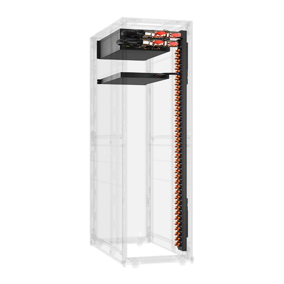
Page 5: Coolant Distribution Manifold (Cdm)
Camlock fittings. Camlock fittings are a globally-available, tool-less connection system where the dimensions of the matting ends are governed by international standards, allowing a male Camlock purchase on one continent to mate seamlessly with a female Camlock purchased on another continent. Asetek InRackCDU Installation, Operation & Maintenance Guide 4... -
Page 6: Server To Cdm Tube Sets
Coolant The server coolant in InRackCDU systems is a mixture of DI water, propylene glycol with some additional additives for corrosion resistance. It is a safe, environmentally friendly liquid. It provides freeze protection and inhibits corrosion and biological growth within the system. -
Page 7: Important Information
Material damage may be caused to the monitoring system if this requirement is not met. Only transport the InRackCDU and CDMs in the original packaging or in packaging that protects it from impacts and jolts. ... - Page 8 The InRackCDU system ships out from the factory in a rack. When the customer orders the InRackCDU system and LC Server at the same time, the water- cooled tubes that connect the InRackCDU system and LC Server are connected by the factory.
-
Page 9: Tools & Materials Required
Tools & Materials Required The following tools and supplies are needed to unpack and install the InRackCDU System: Tool Usage Prepared by Screwdriver with Phillips #2 to install CDU cabinet and CDM into Rack Factory Tin Snips to open packing box... -
Page 10: Installation
For bottom feed connections, the minimum size opening that needs to be cut in the floor tile is 150mm x 150mm. Important: For rack widths 700mm, install the pipe adapter in between the facility pipe connection on the CDU and facility hose. Pipe adapter Asetek InRackCDU Installation, Operation & Maintenance Guide 9... -
Page 11: Mounting The Cdms To The Rack
3. Place the CDM inside the rack without hanging it on the CDM Holder 4. Rout the cable tie into a slot in the CDM bracket as below picture Cable tie 5. Hang the CDM into the CDM bracket 6. Tighten the cable ties. Asetek InRackCDU Installation, Operation & Maintenance Guide 10... -
Page 12: Connecting Cdu Cabinet To Cdm
If there is a water leak in the CDU cabinet, the drain will drain from the end of the drain tube. Please prepare the drainage facilities at the facility side. Attach venting tube Drain tube Asetek InRackCDU Installation, Operation & Maintenance Guide 11... -
Page 13: Connect Power And Networking To Monitoring System
There is a 12V DC supply available for the sensor. Each sensor port can deliver max 150mA. The external sensors are connected to the monitoring box as shown on the picture below. External sensor #1 External sensor #2 Asetek InRackCDU Installation, Operation & Maintenance Guide 12... - Page 14 Pin layout for connection cable between external leak sensor and monitoring box is shown below: White: External Leak Sensor #1 Red: External Leak Sensor #2 Sense Input 12V Out Contact Asetek to learn more about 3 party leak detection solutions. Asetek InRackCDU Installation, Operation & Maintenance Guide 13...
-
Page 15: Configure Monitoring System On Network
Additional information on the monitoring system is provided in the monitoring manual. Recommended Setting of Monitoring System Refering the leaflet of the InRackCDU system ”Recoomended Setting of Monitoring System”, please define to setting values of Monitoring System. Additional information on the monitoring system is provided in the monitoring manual. -
Page 16: System Startup
Preparation of floor for InRackCDU with for facility tubes connection in the bottom The flooring for InRackCDU with facility connection from the bottom must be prepared with a 100x150mm opening for routing of the facility hoses from underneath the floor to the InRackCDU inside the rack as below example. - Page 17 Open pressure release valve and keep it open until the liquid flow out of the release valve stops. Close the pressure release valve and disconnect facility hoses. Asetek InRackCDU Installation, Operation & Maintenance Guide 16...
-
Page 18: Connect Server Tube Sets To Cdm
Once this initial process has been completed, all the servers may be powered off and on simultaneously. This row-by-row power on sequence only needs to be followed the first time all servers are connected to the InRackCDU System. Asetek InRackCDU Installation, Operation & Maintenance Guide 17... -
Page 19: Routine Maintenance
7 Routine Maintenance There is a reservoir in the 4u InRackCDU cabinet. As the liquid cooling system runs, liquid gradually permeates through the rubber tubing and plastic parts in the system. The reservoir contains sufficient fluid to replenish the liquid that permeates out of the system for more than 50,000 hours of 24/7/365 operation. -
Page 20: Replacing Power Supplies
Before screwing the plug back into the reservoir, replace the black O-ring on the plug. Replacement O- rings (Asetek PN P00004415) are included on the zipper bag on the below picture and can be purchased from Asetek. Please keep O-rings by customer for preparing that servicemen will use and replace O-ring. -
Page 21: Other Abnormalities And Failures
Collected liquid should be transferred to a sealable container and this container should be sealed and marked as containing “Enhanced Propylene Glycol”. Dispose of waste and residues in accordance with local authority requirements. (Collected liquid may be disposed of by taking to a Asetek InRackCDU Installation, Operation & Maintenance Guide 20... -
Page 22: Appendix Ii - Cdu Specifications
Power Supply Voltage: 100VAC to 240VAC, 50/60Hz, auto-range Connector: IEC320 C14 (male) Power Consumption: 70W Max, 15W Normal Operation Electrical Requirements Physical Layer: Copper wire, RJ-45 Connector Application Layer: Web browser interface, SNMP, e-mail alerts & alarms Asetek InRackCDU Installation, Operation & Maintenance Guide 21... -
Page 23: Appendix Iii - Facility Water Requirements
Facilities liquid shall be clear of particulate matter greater than 0.84mm in any dimension. Corrosion Inhibition Compatible with wetted materials in CDU cabinet: • Copper • Brass • Stainless Steel Pressure drop across the InRackCDU facility side Asetek InRackCDU Installation, Operation & Maintenance Guide 22... - Page 24 Turbidity <20 NTU (Nephelometric) Glycol concentration Max 38% Total Hardness < 100mg/L. Calcium (Ca) and Magnesium (Mg) Total Organic Carbon (TOC) <25 mg/L Suspended Solids (SS) <25 mg/L Iron (Fe) <10 mg/L Asetek InRackCDU Installation, Operation & Maintenance Guide 23...
-
Page 25: Appendix Iv - Installation Of Inrackcdu In Pcr-M2 Rack
Appendix IV – Installation of InRackCDU in PCR-M2 rack Important: Do not power on server node until installation is completed. In addition, perform the installation and powering up in the sequence described in Chapter”6.4 Powering Up Servers” the first time the rack is powered on after installation in the factory. - Page 26 Screw M6x12 / TX30 Position CEC P/N: A3C40127330 Bottom view Top view Installation of the CDM-Holder (Torque of the nuts = 5,2Nm) Nut M5 P/N: A3C40133896 CDM-Holder P/N: A3C40196331 Top view Bottom view Asetek InRackCDU Installation, Operation & Maintenance Guide 25...
-
Page 27: Appendix V - Installation Of Transportation Lock In Pcr-M2 Rack
Installation of the transportation lock (Torque of the screws = 5,2Nm) Spring Nut M6 P/N: A3C40133889 Screw M6x12 / TX30 P/N: A3C40127330 Position Vertiv Position CEC Mounting position of spring nuts Position CEC Position Vertiv Asetek InRackCDU Installation, Operation & Maintenance Guide 26... -
Page 28: Appendix Vi - Thermal Performance Data
Appendix VI – Thermal performance data This appendix includes some typical 4u InRackCDU V2 80kw performance data for reference. Simulations of unique rack configuration can be obtained from Asetek on request. Asetek InRackCDU Installation, Operation & Maintenance Guide 27... - Page 29 Asetek InRackCDU Installation, Operation & Maintenance Guide 28...
Need help?
Do you have a question about the InRackCDU and is the answer not in the manual?
Questions and answers